


cruiser54
-
Posts
9413 -
Joined
-
Last visited
-
Days Won
14
Content Type
Profiles
Forums
Gallery
Everything posted by cruiser54
-

Part-Time light on / gear lever in RWD
cruiser54 replied to Cali Cruse's topic in MJ Tech: Modification and Repairs
Pete, you're flawed on one statement. That the CAD gives us problems 30 years down the road. LOL. That system was problematic when new!!!!! -
Replaced Crank Position Sensor
cruiser54 replied to Teapott's topic in MJ Tech: Modification and Repairs
www.cruiser54.com is the best place to go for the most current Tips. I'll attach 2 of them that apply to this thread. Tips 1 through 5 should be completed ASAP! CRUISER'S MOSTLY RENIX TIPS RENIX GROUND REFRESHING OCTOBER 30, 2015 SALAD 45 COMMENTS The Renix era XJs and MJs were built with an under-engineered grounding system for the engine/transmission electronics. One problem in particular involves the multiple ground connection at the engine dipstick tube stud. A poor ground here can cause a multitude of driveabililty issues, wasted time, failed emission tests, and wasted money replacing components unnecessarily. All the components listed below ground at the dipstick tube stud: Distributor Sync Sensor, TCU main ground, TCU “Shift Point Logic”, Ignition Control Module, Fuel Injectors, ECU main ground (which other engine sensors ground through, including the Oxygen sensor, Knock Sensor, Cruise Control and Transmission Sync signal. All extremely important stuff. The factory was aware of the issues with this ground point and addressed it by suggesting the following: Remove the nut holding the wire terminals to the stud. Verify that the stud is indeed tightened securely into the block. If the whole stud turns, you can use a 7/32″ six point socket or wrench to hold it so the nut can be removed. Worst case, cut the wires and remove the stud and nut. Install new terminal eyelets on the wires when going back together. Scrape any and all paint from the stud’s mounting surface where the wires will attach. Surfaces must be clean, shiny and free of any oil, grease, or paint. Inspect the wire terminals. Check to see that none of the terminals are crimped over wire insulation instead of bare wire. Be sure the crimps are tight. It wouldn’t hurt to re-crimp them just as a matter of course. Sand and polish the wire terminals until clean and shiny on both sides. Apply a liberal coating of OxGard, which is available at Lowe’s and other stores. Reinstall all the wires to the stud and tighten the nut down securely. While you’re in that general area, locate the battery negative cable which is fastened to the engine block just forward of the dipstick stud. Remove the bolt, scrape the block to bare metal, clean and polish the cable terminal, apply OxGard, and reattach securely. Another area where the grounding system on Renix era Jeeps was lacking is the engine to chassis ground. There is a braided cable from the back of the cylinder head that also attaches to the driver’s side of the firewall. This cable is undersized for its intended use and subject to corrosion and poor connections at each end. Remove the cable end from the firewall using a 15mm wrench or socket. Scrape the paint off down to bare metal and clean the wire terminal. Apply OxGard. Reattach securely. Remove the other end of the cable from the rear of the head using a 3’4″ socket. Clean all the oil, paint and crud from the stud. Clean the wire terminal of the cable and reattach securely with a liberal coating of OxGard. 2 STRONG suggestions regarding the ground system: I prefer to add a #4 gauge cable from the firewall to a bolt on the rear of the intake manifold, either to a heat shield bolt or fuel rail bolt. A cable about 18″ long with a 3/8″ lug on each end works great and you can get one at any parts store already made up. NAPA has them as part number 781116. A further improvement to the grounding system can be made using a #4 cable, about 10″ long with 3/8″ terminals at each end. Attach one end of this cable to the negative battery bolt and the other end under the closest 10mm headed bolt on the radiator support just forward of the battery. NAPA part number 781115. For those of us with Comanches, it’s very important to remove the driver’s side tail lamp assembly to access the ground for the fuel pump. Remove the screw holding the black ground wire. Scrape the paint from the body and corrosion from the wire terminal. Add a 10 gauge wire, with an eyelet on each end, from that grounding point to a bolt on the frame. Better yet, on both Cherokees and Comanches, complete Tip 29 for the best fuel pump grounding. Be sure to scrape all mounting points to bare metal and apply OxGard also. If you want to upgrade your ground and battery cables with custom made parts, contact Neal at www.meanlemons.com CRUISER'S MOSTLY RENIX TIPS THROTTLE BODY TO MAP SENSOR HOSE FIX JANUARY 23, 2016 CRUISER54 29 COMMENTS The Renix throttle bodies have a strange and failure prone connector on the side where the MAP supply originates and then runs up to the MAP sensor located on the firewall. This hose/pipe assembly is no longer available for purchase. The real kicker here is how critical this line is in supplying the correct vacuum signal to the MAP, the most relied upon sensor for the ECU to read regarding air/fuel ratio. Any cracks, melted spots, or loose rubber connectors can cause major starting and driveability issues. There’s a simple fix though. All that’s required is a 1/8” NPT tap, a new throttle body gasket ( Napa FPG 60742 ), a vacuum fitting (Napa 05703-B102), two vacuum elbows (Napa CRB2670), and a length of new plastic piping (Napa CRB2672). Remove the throttle body and take it to the workbench. Using an oiled tap along with a driver, carefully thread the lower of the 2 holes of the throttle body where the old fitting was plugged in. Don’t go too deep. These are pipe threads. Flush the hole with carb cleaner and inspect for any left over cuttings. This is an excellent time to do a complete throttle body and IAC cleaning. See Tip 11. Take the vacuum fitting (05703-B102 ) and apply a LITTLE bit of thread sealer on the threads only. I prefer Permatex #2 but almost anything is fine. . Carefully screw the fitting in until snug. Install one of the vacuum elbows on the MAP sensor so it points toward the throttle body, and the other vacuum elbow on your new throttle body fitting so it points up to the MAP sensor. Cut a length of the new plastic tubing (approximately 13 inches) to fit between the vacuum elbows and install it making sure there is enough slack for some engine movement. Route it according to the photo. We don’t want any rubbing or chafing with engine movement. Not a bad idea to use some contact cement or Gasga-Cinch sparingly on the tubing to elbow connectors. -
Pete is referring to this: CRUISER'S MOSTLY RENIX TIPS IMPROVING BLOWER MOTOR PERFORMANCE NOVEMBER 28, 2015 CRUISER54 24 COMMENTS On 87 to 90 MJs and XJs, the blower motor’s factory grounding point is on the driver side inner fender under the sheet metal screw. This ground is shared with windshield wipers, front windshield washers, rear windshield washers, AC clutch relay, fan control relay, fog lamps, fan motor, headlamps, front turn signals, front side markers, and park lamps. So your blower motor has its ground point 10 feet away from where it is located!! What we’re going to do is leave that ground intact and also ground the blower motor on the passenger side inner fender much closer to the blower motor itself. This will also benefit the other components on the factory ground circuit. Take this opportunity to refresh the factory ground as a matter of course. Remove the screw, scrape the surface to bare metal and reinstall the screw securely. Here’s what I do to get the ground much closer to the blower motor and add another ground point to this overloaded ground circuit. Find the blower motor connector on the passenger side. Red and Black two wire connector. Find a location where the black wire can be made to reach the passenger side inner fender, and cut the wire. You may have to do some rerouting of the harness to achieve this. Take both cut pieces of wire and put them together into a yellow eyelet and crimp. Fasten the eyelet to a place on the passenger side inner fender with a sheet metal screw after applying OxGard to the contact surfaces. Be sure to scrape the attaching point on the fender to bare metal first. Your blower motor will now turn faster and last longer, and the other electrical components on the circuit will benefit from a better ground path.
-
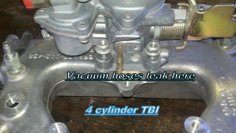
Put a wrench or socket on all the intake and exhaust manifold bolts. Likely loosened up. Refresh the grounds per my Tips. 20 minute job. Check the vacuum lines in the photo below.
-
Instrument cluster ground
cruiser54 replied to Vineyard86manch's topic in MJ Tech: Modification and Repairs
CRUISER'S MOSTLY RENIX TIPS IMPROVING THE INSTRUMENT PANEL GROUND NOVEMBER 17, 2015 SALAD 13 COMMENTS The ground point for the complete instrument cluster on your XJ or MJ is located up under the driver’s side dash. If you lay on your back and look up under there with a flashlight, without wearing a hat, you will see a black wire attached to a shiny piece of metal almost directly above the hood release knob. The screw will have either a ¼” or 5/16″ head on it. This ground point is responsible for handling the ground circuit for the following items: Dome lamps, seat belt and key warnings, transmission power/comfort switch, wiper switch, headlamp switch and delay module, fog lamp switch, cargo lamp switch, all instrument panel grounds and illumination, power windows and door locks, cruise control dump valve, and a few more things. The problem is that where the ground point is located does not share good contact with the chassis where the ground should be. The solution is simple: Make up a jumper wire with #10 gauge wire about 10″ long. On one end, crimp on a ¼” round wire terminal. On the other end, crimp on a 3/8″ round wire terminal. Remove the screw from the existing ground wire and attach the small terminal of your jumper so that the original wire and your new jumper share the same attaching point, one over the other. Look above the driver’s side plastic kick panel just forward of the top of the hood release knob. You will see an 8mm stud there. Attach the large terminal end there with a washer and nut over it tightened securely. Use a coating of OxGard at all ground contact surfaces when attaching the screw and nut. **Special note for Comanche owners: Make your jumper wire 12″ long and attach it on the driver’s side kick panel close to the fusebox on the 8mm stud.** -
CRUISER'S MOSTLY RENIX TIPS RENIX TPS ADJUSTMENT OCTOBER 30, 2015 SALAD 136 COMMENTS Before attempting to adjust your TPS, there are a few things that need to be done. Be sure the throttle body has been recently cleaned. It’s especially important that the edges of the throttle butterfly are free of any carbon build-up. With the KEY OFF, and using the positive (red) lead of your ohmmeter, set on the lowest scale, probe the B terminal of the flat 3 wire connector of the TPS. The letters are embossed on the connector itself. Touch the black lead of your meter to the negative battery post. Wiggle the wiring harness where it parallels the valve cover and also over near the MAP sensor on the firewall. If you see more than 1 ohm of resistance, or fluctuation in your ohms reading, some modifications to the sensor ground harness will be necessary. The harness repair must be performed before proceeding. It is covered in detail in Tip 6. TPS ADJUSTMENT FOR ENGINE ISSUES Both Renix manual and automatic transmission equipped XJs and MJs have a flat three-wire connector to the TPS which provides data input to the ECU. The three wires in the connector are clearly embossed with the letters A, B, and C. Wire “A” is positive. Wire “B” is ground. DO NOT UNPLUG THE CONNECTORS! KEY ON, measure voltage from “A” positive to “B” ground by back-probing the connectors. Note the voltage reading–this is your REFERENCE voltage. KEY ON, back-probe the connector at wires “B” and “C”. Measure the voltage. This is your OUTPUT voltage. Your OUTPUT voltage needs to be seventeen percent of your REFERENCE voltage. For example: 4.82 volts X .17=.82 volts. Loosen both T-20 Torx screws attaching the TPS to the throttle body and rotate the TPS until you have achieved your desired output voltage. Tighten the screws carefully while watching to see that your output voltage remains where it is supposed to be. If you can’t achieve the correct output voltage, replace the TPS and start over. Sometimes, after adjusting your TPS the way outlined above, you may experience a high idle upon starting. If that happens, shut the engine off and reconnect your probes to B and C. Start the engine and while watching your meter, turn the TPS clockwise until the idle drops to normal and then rotate it back counterclockwise to your desired output voltage. TPS ADJUSTMENT FOR AUTOMATIC TRANSMISSION ISSUES Renix automatic transmission-equipped XJs and MJs have a TPS with two connectors. There is a flat three-wire connector, same as the manual transmission vehicles have, and it is tested the same as outlined above—FOR ALL ENGINE MANAGEMENT RELATED ISSUES. However, the automatic TPS also has a square four-wire connector, clearly embossed with the letters A,B,C, and D. It only uses three wires and provides information to the Transmission Control Module. THIS SQUARE FOUR WIRE CONNECTOR IS USED FOR TRANSMISSION/SHIFTING RELATED ISSUES ONLY. First off, DO NOT UNPLUG THE CONNECTORS! KEY ON, measure voltage between “A” positive and “D” ground by back-probing the connector. Note the voltage. This is your REFERENCE voltage. Back-probe the connector at wires “B” and “D”. Measure the voltage. This is your OUTPUT voltage. Your OUTPUT voltage needs to be eighty-three percent of your REFERENCE voltage. For example 4.8 volts X .83=3.98 volts. Adjust the TPS until you have achieved this percentage. If you can’t, replace the TPS and start over. So, if you have an automatic equipped XJ your TPS has two sides–one side feeds the ECU, and the other side feeds the TCU. For those with a MANUAL TRANSMISSION–the TPS for the manual transmission XJs is stupid expensive. You can substitute the automatic transmission TPS which is reasonably priced. The square 4 wire connector is just not used.
-
Good idea. Always before adjusting TPS..
-
Glad someone caught that besides me!!
-
What year? What engine?
-
Remember when they sold NSSs for the price of reverse light switches? about $7 or so.
-
My local Napa has a Wix sale every once in a while. Ask them.
-
Congrats to you both.
-
Need Tail lights
cruiser54 replied to emissioneracarfan's topic in MJ Tech: Modification and Repairs
Hmmmmm. Taillights, eh? -
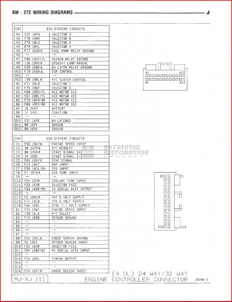
Probe C1 And D1 just like you would test the cPS in the engine bay.
-
You could test it at the ECU. Maybe something is getting lost in the wiring.
-
Have you tested the CPS output when hot?
-
Intermittent No Start
cruiser54 replied to krustyballer16's topic in MJ Tech: Modification and Repairs
Test for pulse on any colored wire on any injector plug. Wiggle wires near the back of valve cover while cranking. Those wires were prone to abrasion. -
Intermittent No Start
cruiser54 replied to krustyballer16's topic in MJ Tech: Modification and Repairs
STILL do the Tips!!!! -
428 is the most common one IIRC and is for an auto trans. Works well in either application
-
Misfire at idle - Renix 2.5 TBI
cruiser54 replied to WeezyBlue's topic in MJ Tech: Modification and Repairs
Clean ground at firewall. Bare metal. Check the vacuum lines at the intake manifold. Check the vac line to the MAP sensor. Check the intake manifold bolts to see if they've come loose. -
coolwind's write up is excellent and should be done by everyone who hasn't done it before winter hits. Numerous electrons will be saved as a result.
-
EXCELLENT!!!!!
-
Truck acting very weird
cruiser54 replied to SouthernComanche's topic in MJ Tech: Modification and Repairs
This ^^. -
Intermittent No Start
cruiser54 replied to krustyballer16's topic in MJ Tech: Modification and Repairs
Get the Tips done.......... -
Some clarification. Temp and oil sending units for idiot lights can NEVER be used for ANY gauges. Aftermarket gauges will require changing the sending units to match their gauges. You can use the same location you remove your old senders from. Be aware you may have to do some adapting there. And then there is the accuracy issue with crappy car parts now....... Is this really worth it to you? There's no real easy way to do this if your skill level isn't up to it.