
Gojira94
-
Posts
677 -
Joined
-
Last visited
Content Type
Profiles
Forums
Gallery
Everything posted by Gojira94
-
GM ECMs from the same period have 4 primary parameters for IAC, where 0 IAC steps/ counts is pintle fully extended, closing off airflow and max IAC steps is fully retracted with max airflow possible: IAC park steps (where the pintle moves to at key off); shouldn't change. IAC initial steps (where the pintle moves to at key on) most likely CAN change/ "learnable" on Renix ECU. IAC minimum steps (lowest number of steps open possible/ pintle fully extended); usually low but not quite a zero value. Probably learnable on Renix ECU? IAC maximum steps (highest number of steps open possible/ pintle fully retracted); high, maybe 255 (256 byte words is values from 0-255). Probably learnable on Renix ECU? There are also stall saver IAC functions as well as target idle, acceleration enrichment ("throttle cracker") and deceleration enleanment IAC trims that operate in tandem with fuel and timing advance/ retard trims for these conditions (topic for another time). Also wondering if target idle has been learned artificially low (operates as a function of IAC vs TPS position) due to the vacuum leak it's been living with. A large vacuum leak can 'learn' the IAC positions to maintain idle/ run pretty far from default values. Have you disconnected the battery since fixing the vacuum leak? You might try it so the ECU can 'learn' from default values for IAC initial, min/max parameters, and from there follow the relearn procedure Ohm provided as needed. And TPS check/ adjust also a good suggestion from Ohm & pizzaman09.
-
 Yes, hydraulic lifters (flat tappet and roller tappet) will leak down. That's normal, since you're literally squeezing the oil out going past zero lash. When the engine's running, oil pressure through the lifter gallery will keep them pumped up and immediately take up the resulting slack. Hit zero lash, add preload, done. Solid roller or mechanical flat tappet require hot lash with a feeler gauge, as accurately stated above. Totally different animal. I cautioned against too light a preload, which is especially consequential for hydraulic roller lifters. In the GM world, the "LS7" lifter has been popular and misunderstood. A fair number of guys were just blindly going 3/4 turn past zero lash. On a 7/16" x 20 stud, that's .050" which is fine, as that lifter wants to be somewhere between .045" and .080." On a 38/" x24 stud, that's .031" and the lifter rollers would skate and destroy the cam lobes and lifter rollers, scattering hardened metal throughout the engine. That being said... the lifter you listed above has no generally known specs for plunger travel distance. Short of measuring the lifter plunger travel on the p4529220, go with the FSM valve adjustment instruction. That should get you safely into the lower-middle range of its travel/ cushion. Pushrod length is important to at least get pretty close for valve stem longevity, and pushrods generally aren't that expensive. Very nice build you've got there!
 -
Ideal rocker geometry has the rocker at a 90* angle to the stud at the mid point of cam lobe lift. This keeps the roller tip well centered on the valve stem and prevents any sideloading on the valve stem that might otherwise occur. Very few cams have such a difference between intake valve lift and exhaust valve lift as to make it ideal to have different pushrod lengths for each ( > .025" lift split ). Use an adjustable pushrod length checker of appropriate size range. With a magnetic dial indicator on the tip of the rocker directly above the roller tip/ valve stem, roll the engine over slowly. As you come off the base circle of the cam, the nose of the rocker will drop. Keep rolling the engine slowly until you reach max lobe lift and divide that by 2. Roll the engine over again until that valve is closed and again begins to open. when you reach the /2 number you got from max lift, STOP. Adjust your pushrod length checker until the rocker and stud are 90* from each other at zero lash. Imaginary line through the center of the trunnion and roller tip is one line, center line of the stud is the other. If your preload, based on the plunger travel exceeds .025" add that to the pushrod length you get from the pushrod length checker. Simple low tech pushrod length approach without a dial indicator: use gear marking compound on the valve tip and lengthen/ shorten the pushrod length checker, rolling the engine over, repeating until you have a narrow sweep pattern centered on the valve tip.
-
You shouldn't be able to lift the roller tip off the valve stem, obviously. If you run out of threads for the poly locks before you get to the trunnion on the rocker, you've got the wrong studs. As for preload, it very much helps to know the plunger travel distance spec on the hydraulic lifter. Say if it's got .060" of travel, and you're running 3/8 x24 studs you'll want to go 3/4 to 1 turn past zero lash to get between .031" - .042" into the lifter's travel range (about the middle of it). Pushrods could also be too short if I'm understanding what you're saying...
-
I don't think I knew that. My old man was there from 69-71, worked with the Chieu Hoi under Hop Tap in III Corp and IV Corp. I have 2 sets of his tiger stripes. When I was a kid in the 70s, every Sunday at my grandparents' house there were vets from WWII, Korea and Vietnam around. One by one they've all gone. My old man is the only one left, he'll be 80 in January. Every time I see a vet wearing a Vietnam hat or shirt, I make a point of speaking to them, thanking them and telling them what I remember of the men who served in all the wars, and how much they're appreciated and missed. You're very much appreciated.
-
I'm essentially doing the same as you're considering, running an HO engine with a 89-90 Renix manual harness/ computer. Your advantage is you have all your Renix-compatible sensors already, only question is if you've done the open cooling system upgrade. The rad I got has a plugged boss for the Renix style fan switch, which was a pleasant surprise, so I'm using the Renix fan switch. My donor is a 93 YJ, so I'm capping the port for the fan switch in the thermostat housing. If I had a Renix t-stat housing, I'd run it instead for the same reason. Only other caveats I can think of are to swap over the speedo gear and possibly the TC indicator switch, not sure if it's the same but probably is. Little things like reverse light switch pigtail being different is a possibility. If you're comfortable with refreshing the 96 shortblock yourself, new bearings throughout/ inspect all journals is a good thing, though cam bearings can be tricky without the right tools. Very light DIY hone of the bores and new rings would make it pretty happy. So would new valve seals, springs and lapping the valves. Refreshed head with worn rings = burning oil though, and new rings with leaky valve seals also = burning oil so don't do one without the other.
-
Hot engine, smoke and sticky brakes
Gojira94 replied to Virginia's topic in MJ Tech: Modification and Repairs
2 things come to mind: One, an old brake hose on one side (or both) in the front, partially collapsed. Allows fluid to flow to the caliper easily enough but doesn't allow the fluid to move back up the line toward the proportioning valve and master cylinder when the pedal is released (pretty typical of front hose failure). As this inside of the rubber portion of the hose breaks down, crumbs/ sediment settles in the caliper, hose and points upstream, potentially causing small clogs in the proportioning valve and master cylinder. This inhibits normal back and forth flow of the fluid between master and caliper. Two: sediment/ debris in the master's rear compartment (rear portion is for front brakes, front is for rear). Anything that can cause an obstruction to fluid flow can cause the sticking you're observing. This condition can momentarily resolve itself if the rubber crumbs/ sediment move around a bit, but it will come back sooner rather than later. You can open the master, and if the fluid is dark enough you can't see the bottom of the reservoir, pull it out with a turkey baster and see if you have a lot of sediment in the bottom. This is a good indication that the front hoses are shedding material. The rubber line at the rear is far enough from the master that it usually gums up the wheel cylinders before it gets drawn all the way back to the master. If your rear brake bias proportioning valve is still in place, it could potentially get fouled with debris from the rear hose, but I'd focus on the front brakes as the primary culprit and keep the rears in mind as a near-future item to inspect/ address. Probably no worse than replacing the front hoses, quick flush of the calipers, cleaning out the hard lines up to the master, the master itself and refilling/ bleeding to start with. -
Bottom Radiator Bushings - Dimensions Needed
Gojira94 replied to Salvagedcircuit's topic in MJ Tech: Modification and Repairs
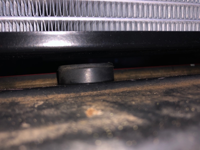
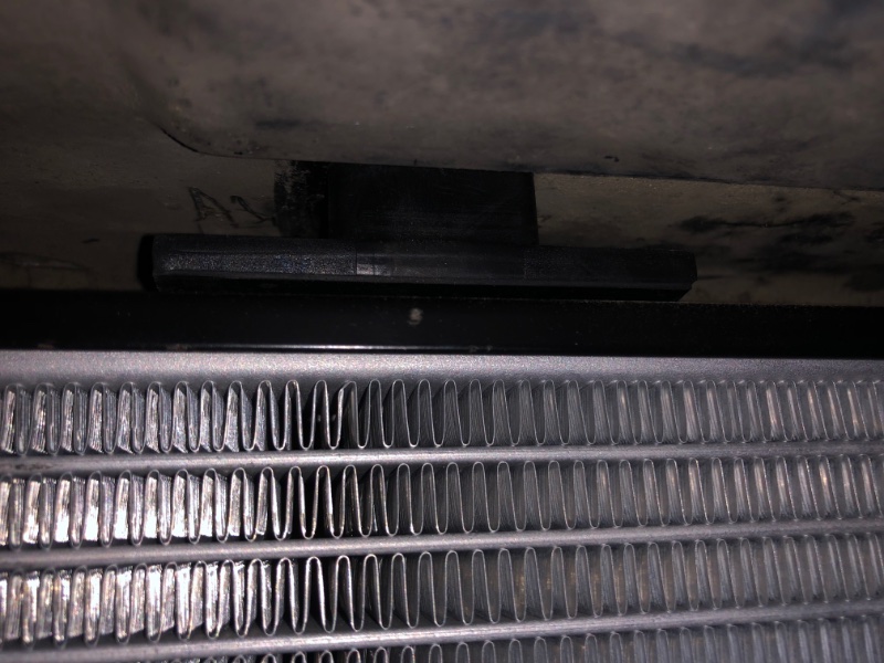
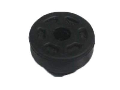
The Honda condenser supports are a winner. And they’re ubiquitous. I gathered 6 from my local boneyard in 10 minutes, paid about a quarter each. Pretty much any Accord or Civic from 2003-2017. I cleaned up 3 and popped them in with a drop of spray silicone. I can’t say about a closed system radiator, but this is from an open system setup radiator, 87 upper radiator support that originally held a 4 cyl rad, and new upper radiator cushions: upper cushion, right side: lower, right side: middle one could use something taller since there’s no pin here on the HO/ open system rad- maybe the closed system rad has a 3rd pin here?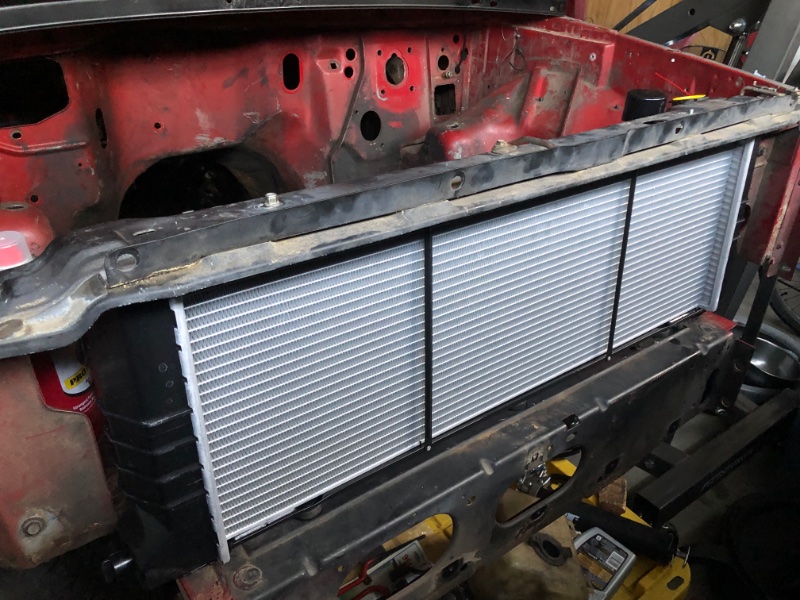

-
Sorry, GM terminology. “Power Enrichment” mode. Like when TPS positive delta (change) of 40% or whatever is detected from TPS, ECU enters a mode of adding fuel, much more than say for Acceleration Enrichment for mild/ moderate acceleration. A WOT or PE mode usually also ignores O2 input, stops doing ST fuel trim and LT fuel trim learning and commands a fuel amount from a table lookup of RPMs vs manifold pressure in kPa. Why I asked about ST fuel trims gong to zero. Indicated to me that the ECU purposely stopped doing the math, possibly for a false WOT mode or maybe a false closed throttle indication from the TPS. We used to hook up a fuel pressure gauge and tape it to the windshield to confirm fuel pressure when issues were suspected. Since these trucks don’t have a pressure sensor at the rail, the REM can’t tell you if you suddenly lose fuel pressure. Loading up too much extra fuel feels almost the same- bogs/ dies and then clears up when you lift.
-
Renix EGR block off plate
Gojira94 replied to Htchevyii's topic in MJ Tech: Modification and Repairs
Vinegar... real quick lol. -
How did you arrive at the conclusion that fuel is cutting off? You say short term fuel trims look normal- from slightly negative to slightly positive? How much both ways, min/max ST trims? You say that while driving the ST goes to/ stays at zero? Not many things turn off ST fuel trims, but one of those is when PE mode (WOT) is commanded/ detected. If the WOT switch is glitching it may fool the ECU into thinking it's in WOT, zero the ST trims, add an arbitrary amount of extra fuel otherwise suitable for PE mode at whatever RPM/MAP it's at, and bog until you lift out of the throttle. You might want to test the WOT switch to make sure it's not inappropriately entering PE mode. Procedure here: https://www.jeepforum.com/threads/how-to-test-wot-wide-open-throttle-switch.368246/ Edit: test the TPS, too
-
Yep, mine's in the upper right corner, not really along the top of the blower panel. I'm treating both sides for the rust and sealing from the outside like you did.
-
I have the same leak, passenger side only. Been pondering different ways to get at it, and determine the point of entry. I'm convinced it's coming in between the firewall/ blower panel top edge and the forward cowl panel, from road spray or from a lot of parking nose-down. You've done what I've been thinking already- seal that forward cowl panel's seam from the corner in the left of pic 1. I started prying up along that seam about 1/3 of the way across to get in between the pinch welds and clean, squeeze in a spritz of primer, then seam sealer, and re-compressing the seam flat while the seam sealer dries. Water flowing out of the cowl at the ends/ under the fenders shouldn't settle here unless you're parked nose downhill I don't think. It's definitely coming in the top of the firewall/ blower panel, not the side, in my case.
-
Bottom Radiator Bushings - Dimensions Needed
Gojira94 replied to Salvagedcircuit's topic in MJ Tech: Modification and Repairs
I've followed this thread because I'm also in need of 3 of these. Last week I replaced the compressor and condenser/accumulator in my DD 2003 Accord 2.4/5-spd. Being that my MJ was literally 5 feet away inside the garage I test fitted the grommets from the condenser on the Accord. It was pretty much a perfect fit on the body side, and the inner diameter looked right, though I didn't dig out my radiator and confirm. For $5 each, I'm going to find 3 of these and try it: https://www.hondapartsonline.net/v-2003-honda-accord--ex--2-4l-l4-gas/body-air-conditioning--a-c-condenser (part #6 on the diagram).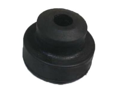
-
The OE part number for all 4.0 applications for MJ and XJ from 87-93 is 4637192. The body of this pump is longer than most of the aftermarket offerings, including the Bosch 69302, Delphi FE0108 and the Walbro 5CA234 noted above. These shorter pumps seem to be turbine pumps, where as the longer ones like OE and the Carter P90011 are likely roller vane (louder, less efficient). The longer ones (about 170mm) are easier to fit but likely have somewhat shorter service life inherent in the design, while the shorter ones (about 135mm) require some cobbling but likely quieter and last longer. IMHO the cobbling required to use the turbine design is worth it, though you need to make sure the end result has the inlet of the pump at the same position as it would be with an older, longer roller vane design for proper fuel draw from the tank. The most important and most often left out spec for a pump is free flow volume in gal/hr or lph. A lot just throw out a pressure spec, but don't say what the regulation method is, or what volume of flow was required to hit that advertised pressure. Pressure is resistance to flow. You can make high pressure with low flow if you restrict the return enough but the delivery rate at low flow won't meet the demand from the rail/ injectors. Too much free flow rate and you have a hard time regulating it to a usable pressure without putting a lot of strain on the pump. From what I've seen looking at a lot of pumps offered for 4.0 applications prior to the change to 49psi at the rail, the required free flow rate to efficiently make 31-39psi is somewhere between 25-45gph (94-170lph).
-
Ohm and cruiser54 are on it- very rich. A weak O2 sensor will do some of it, and as said, exhaust leaks upstream from it will fool it into adding fuel as it will see what appears to be a lean condition. Start with eliminating leaks at the manifold as cruiser54 said, any and all vacuum lines 100% leak-free, cruiser's tips for better sensor grounds, also check throttle body gasket in tandem with the line to the MAP sensor. Check plugs/ gap replace as necessary if fouled, gap at .035." If engine temps aren't getting up where they need to be (any number of mods can make it run cooler than it should) then it'll be stuck rich. Inaccurate coolant temp signal to ECU can also cause ECU to add more fuel than it should (reads colder than actual). High NOx sounds like EGR not working as well as it should. Ignition timing (over advanced) is virtually eliminated with electronic spark control. Gunked up chambers/ valves can add to high NOx. When you're rich and also have high NOx, you have 2 distinct and separate issues.
-
Well done, and thanks for the follow-up.
-
Tuned full-length headers for the $#!&ter upstairs. Must sound really good...
-
Adding a GM rearview mirror wiring question
Gojira94 replied to robfg67's topic in MJ Tech: Modification and Repairs
And 93-02 GM F-Bodies. They have L / R switches for 2 independent lamps in the mirror housing, but no other features as you indicated. -
which t-60 torx for the oil filter adapter upgrade
Gojira94 replied to Pete M's topic in MJ Tech: Modification and Repairs
That's exactly what I heard was the answer. I was prepared for several months for an XJ to pop up in my local yard, only to find on day one each was posted available that someone else had gotten exactly that adapter and nothing else. I'd run out on lunch break the day one posted and it was gone. Like surgical precision. Then I found out a guy 1/2 hr. west of here was harvesting and selling them on EBay for $50.00. I actually bought one from him. He cleans them spotless and includes all needed o-rings for immediate installation. I just couldn't be mad at the guy... -
Renix Distributor Indexing question
Gojira94 replied to Gojira94's topic in MJ Tech: Modification and Repairs
So if the original distributor is long gone this is highly unlikely to be an issue, though still a valid fix in some possible cases where the issue is essentially the same? I'm doing a Renix controlled HO engine from a 93 YJ and am installing a decent quality aftermarket distributor. I'll be interested to see the relative positions of cap contacts and rotor on an unmodified aftermarket dizzy. And tip 13 can always be used to fine tune that relationship. -
Renix Distributor Indexing question
Gojira94 replied to Gojira94's topic in MJ Tech: Modification and Repairs
One other possibility- the engineers who wrote the TSB must have known enough about the timing advance/ retard parameter min/max values to say what the relative positions of rotor tip and cap contact are optimal. The calibration may have been written to default to max retard at any time, unless advance was commanded, i.e. the position shown in Cruiser54's tip 13 may actually be 4*, 8*, 12* or whatever* retarded, and the ECU always commands some amount of advance. Extra advance is needed during cranking, quite a bit at idle and lean cruise, and a lot when the throttle is snapped closed at higher RPMs. Some, but not as much as you might suppose in power enrichment in the higher RPMs. In essence, some degree of advance is commanded at all times, except in the case of knock retard, where it would be able to fall back to whatever retard limit corresponds to the position shown in tip 13. In which case tip 13 is gospel if this possible supposition holds true. -
Renix Distributor Indexing question
Gojira94 replied to Gojira94's topic in MJ Tech: Modification and Repairs
With the cap contact at the trailing edge of the rotor tip set as mechanical 0* there's maybe 16-20* arc of rotor tip available for advance in relation to the cap contact. If we knew from the ECU parameters that max advance was, say 12* and max retard was say, 8* you might want to set the rotor/ cap contact relationship for indexing from #1 with the trailing edge of the rotor visible to the right of the cap contact by maybe 4mm or so. Like instead of this: (advance) |-----------------<+>| (retard) Do this: (advance) |--------------<+>---| (retard) -
Renix Distributor Indexing question
Gojira94 replied to Gojira94's topic in MJ Tech: Modification and Repairs
Correct. You may not have enough rotor tip available/ within close range of the cap contact at a certain point ATDC, or have a pretty large gap to jump is my point here. -
Renix Distributor Indexing question
Gojira94 replied to Gojira94's topic in MJ Tech: Modification and Repairs
This is the crux of my question. In knock retard conditions it could possibly be, without a few degrees of rotor tip spared for the programmed limits for that condition.