Search the Community
Showing results for tags 'DIY'.
-
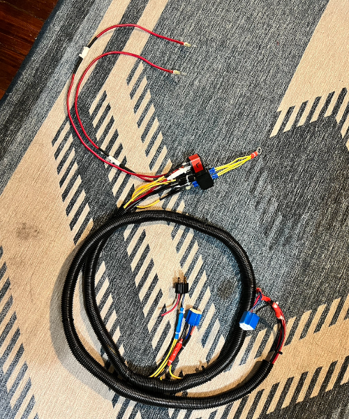
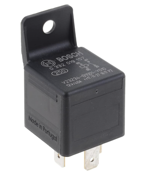
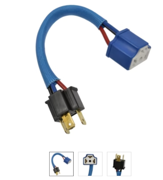
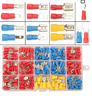
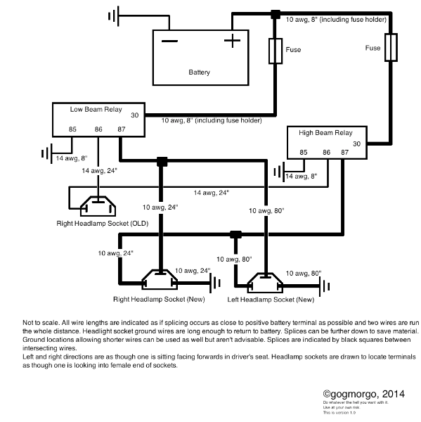
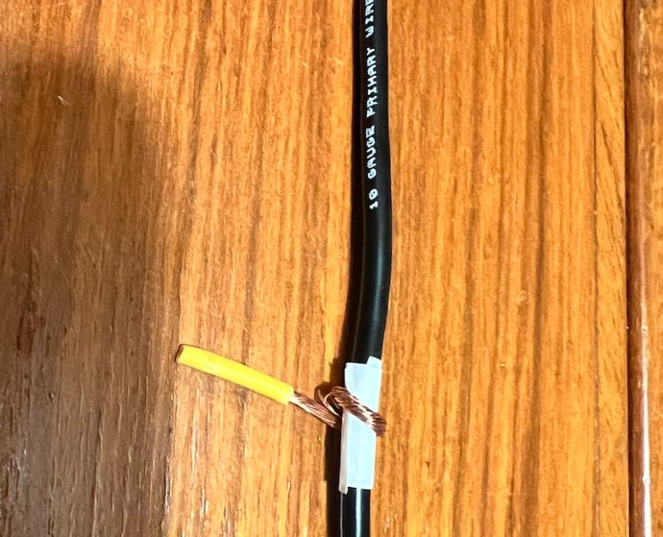
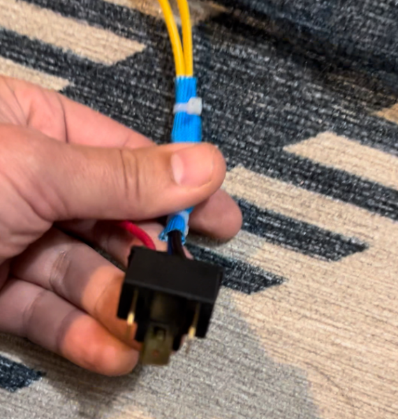
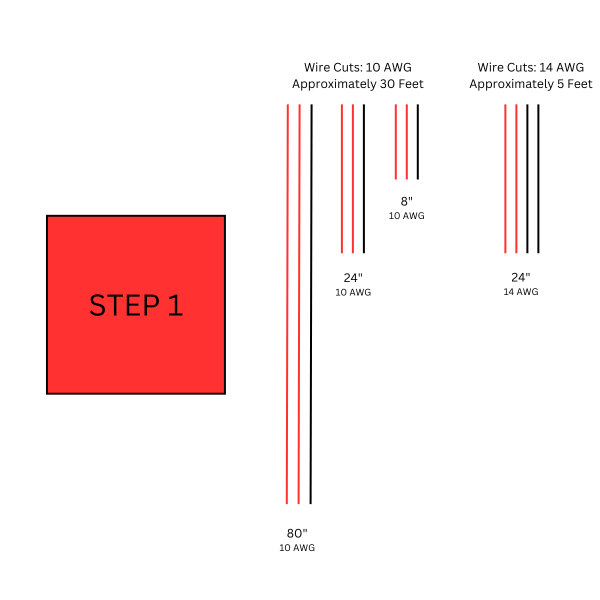
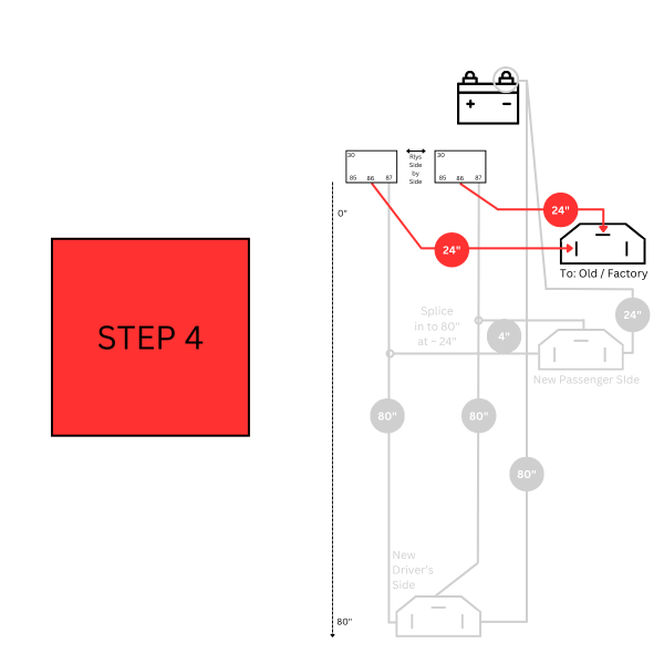
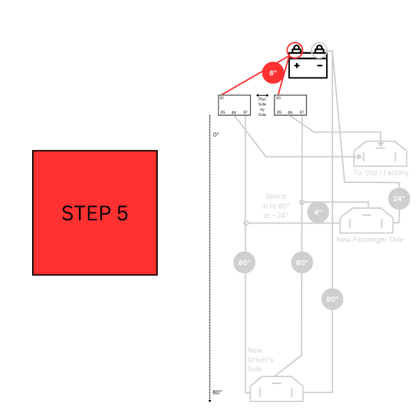
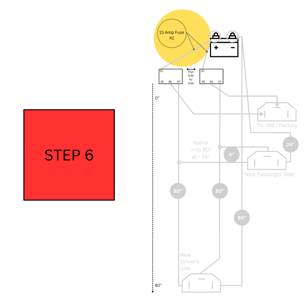
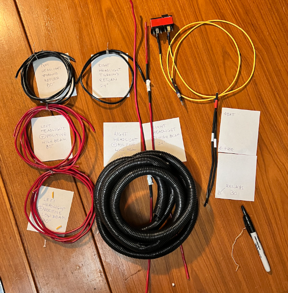
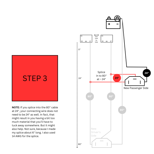
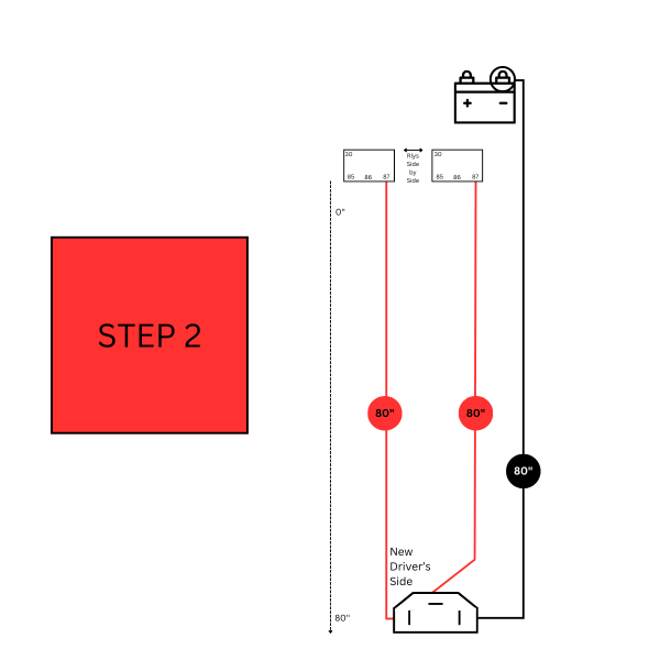
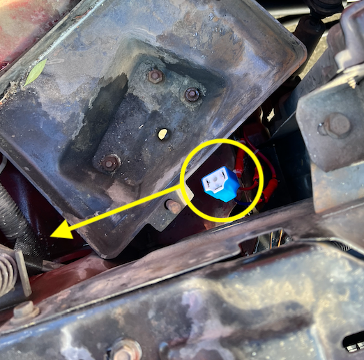
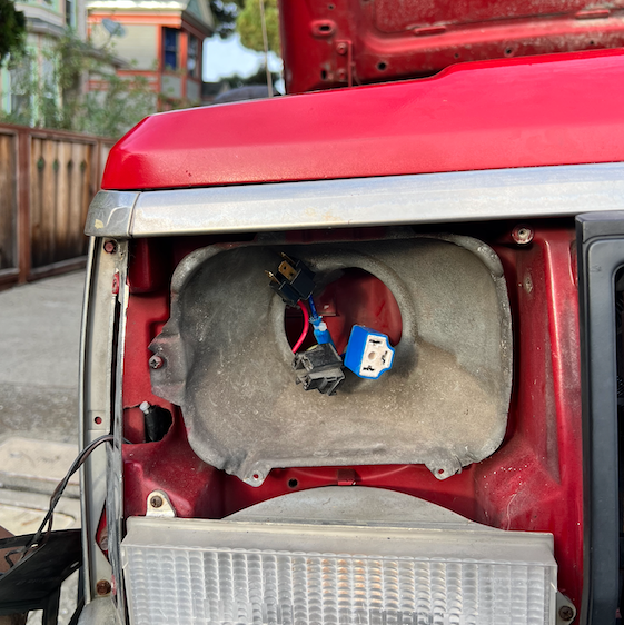
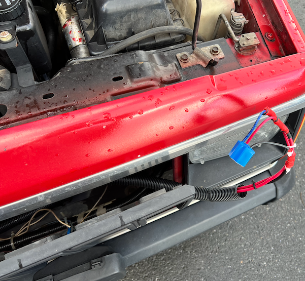
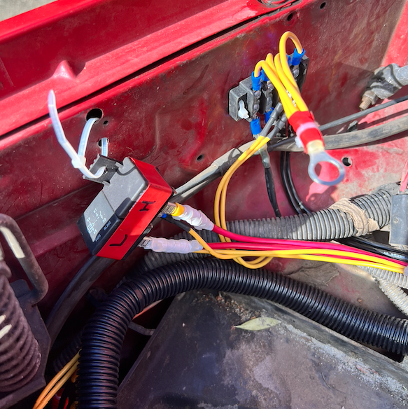
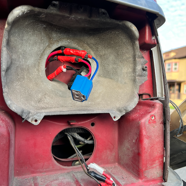
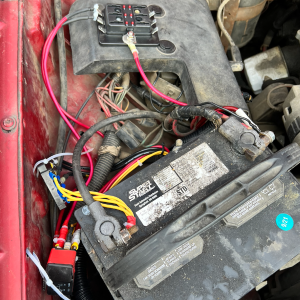
Greetings, Fellow Comanche Enthusiasts! I’ve spent the past few months diving into projects on my 1987 2.5L, 2WD, Short Bed, and this forum has been an invaluable resource. I’ve really enjoyed the time I get to spend just working with my hands and not thinking about emails I have to send. But it occurs to me that I’ve spent a lot of time asking you all questions. I want to give back with a tutorial of my own. I’m much newer to this than many of you, so I welcome any notes on things I could have done better or things I’ve done flat-out wrong. I’m going to write a step-by-step guide on how I built a Headlight Harness Upgrade using @gogmorgo’s diagram. And I’m going to add some diagrams of my own. I hope this ends up helping someone else down the line. NOTE: This is a LONG write up. If you know what you're doing, I suggest taking a look at the diagram below and then the step by step slide show I have at the end. Step 1: Assemble the Materials The first thing I did was add up the total length of 10 AWG and 14 AWG wire that the diagram calls for. The following list turned out to be a little more than I needed, so I think it’s the perfect amount. WIRE: 10 AWG: 30 Feet or 360 Inches 14 AWG: 16 + 48 = 5 Feet or 60 Inches RELAYS: Two 30-amp headlight relays with the following connections: 30, 85, 86, and 87. Here's an example. This one is 40 amps, but you get my drift. H4 HEADLAMP SOCKETS: I scratched my head on this one for a while, because I was unfamiliar with it. Also, all the auto parts websites have my vehicle information by now and they were telling me certain headlights didn’t fit my MJ. I turned off the vehicle-specific search function when I was searching and that helped open up the results. I ultimately went with this one, because it was available locally and the connector was ceramic, which I’ve heard is better than plastic. Makes sense when high temperatures are in play, right? I also wanted to use the male end of one of them to make the connector for the existing OEM harness (see the second picture). OTHER MATERIALS: I had most everything else I needed already, but you’re going to need things like wire strippers/crimpers, big box of wire terminal attachments, a ton of zip ties, and electrical tape. Some other nice-to-haves are a soldering iron, heat shrink wrap, a heat gun, and other electrical components like that. Step 2: Plan Your Build I’ve charged headlong into way too many projects. And honestly, I could have taken more time with this one. But with a project like this, it really helps me to lay everything out in front of me. I looked at @gogmorgo's plans over and over again and cut most of my wire to length before I did anything else. I also labeled my lengths of wire and cross referenced them with the drawings to see if it all made sense. One thing I wish I had done was also plan what kinds of terminal heads I was going to use at each juncture. Doing this would have saved me some time down the line. Step 3: Slow and Steady (Learn From My Mistakes) If you’re brand new, or relatively new (like me), don’t get flustered. Take your time. Like Gogmorgo says, the diagram is not to scale, and it can be hard to visualize at first. Here are some things that took a little while to click for me: Your relays are going to be right next to one another and very close to the battery. Once the new harness is built it will form the shape of a capital “L” — running from the battery on the passenger side of the engine bay, down to the passenger side headlight, then to the driver's side headlight. The short length of the “L” runs from the battery to the passenger side headlight. The long length of the “L” runs from the passenger headlight to the driver’s side headlight. All of the 24-inch lengths of wire correspond to connections at the passenger side headlight. All of the 80-inch lengths of wire correspond to connections as the driver’s side headlight. If you do it like I did, you will have to do at least two splices. These will go on the positive lines. There were two ways I considered doing this. One way would be to connect the positive lines directly to the shovel terminal that attaches to the 87 terminal prongs on each of the two relays (high and low beam). Doing it this way will require the full 24-inches of wire. You may also need to get creative with how you connect the two ends of 10AWG wire to the shovel. Another way is to splice the shorter length of wire roughly at the right angle of the “L” shape that this harness will form when it is installed. Doing it this way will allow you to save a little bit of wire. This second way is the way that I did it. You do not need to splice any of the ground wiring. You do not need to splice the battery-to-relay wiring. Instead, you can just make two 8-inch lengths of wire. On one end attach them to the battery. In the middle, place your in-line fuses. On the other end place a shovel terminal connector to attach to the 30 prong on each relay. If you end up using a left over male H4 connector, remember to connect your wires as a mirror image of the diagram above. I made a mistake here and didn't discover it until the harness was installed. I had to strip wires and make some new connections while crouching at headlight level. Not fun. If you notice, in the picture above, there is a short length of red wire that isn't connected to anything. But that SHOULD have been connected to the high beam relay. Which leads me to No. 7: If you notice in the diagram above, both high beam connections are on the left hand side of the female connector and all the low beam connections are on the top of the female connector. Remember that! Step 4: Splicing & Dicing I was practically brand new to splicing when I started this project. I am also very bad at soldering, and I don’t have a great soldering iron. Here’s how I ultimately spliced the positive cables together: Cut out a very small segment of the 80-inch positive wire. You can use the wire cutters to make the first two cuts around the outer edge of the wire. Then you’ll need a razor blade to cut from one of those cuts to the other cut. Then you’ll peel the slim piece of wire covering off, as if it were a bandage wrapped around your finger. The location of this splice is very close to the connection point for the passenger side headlight connection. The connectors I used came with 14 AWG wires attached to them. I thought about devising a way to maintain 10 AWG all the way to the headlight connection, but I abandoned that idea, and it was helpful to do so. That’s because it was way easier to wrap 14AWG around the exposed splice point of the 10 AWG wire than it would be to wrap the very thick 10 AWG wire around another 10 AWG wire. I took this picture to help you visualize the process. Picture the white electrical tape as the exposed bit on the 10 AWG wire. The yellow bit is 14 AWG wrapped around the exposed portion. Use a soldering iron or thin strips of electrical tape to help secure it in place. As I said, you’ll need to do this on both lengths of 80-inch wire. Step 5: Making Connections Now it’s time to put it all together. For this bit, I made some diagrams of my own. Red is for positive connections. Black is for negative/ground. Connect all the shovel terminals to the wires going to the relays. Connect the new headlight sockets to the wires. Prepare your connection for the existing OEM plug (female plug on the passenger side). I found it helpful to use zip ties to fasten the longer lengths of cable together as I went along. This helped prevent tangles. When I was done, I covered the whole thing in conduit, which I think was helpful when installing in the MJ. MAKE YOUR CUTS MAKE THE DRIVER'S SIDE CONNECTIONS MAKE THE PASSENGER SIDE CONNECTIONS MAKE THE CONNECTIONS FOR THE FACTORY PLUG MAKE YOUR BATTERY CONNECTIONS MAKE AN INLINE FUSE ON THE BATTERY CONNECTIONS Step 6: Hook it Up! I could probably write a whole tutorial on how to do this as well. It took me a long time and I hit some road blocks along the way. Thankfully there is a detailed installation video from K Suspension that you can watch here. The main difference with the harness in this video is that the grounds do not run all the way back to the battery. I opted to create a harness where the grounds return all the way to the battery, because I hoped that would lead to a healthier circuit. By the way, if you don't want to take the time to build your own, or don't feel comfortable doing it, K Suspension and many other companies make this exact harness. Some of them are even cheaper than what it would cost you in money and your valuable time to do it DIY style. But, at least for me, tinkering is part of the fun! Step 6.1: Hook it Up! (Pt. II) OK... Just thought I'd add a few more pics of the actual install. I didn't document this process perfectly. But here goes: It helps to take the batter out completely. This is also good because you know you won't accidentally create a short while the harness is flopping around. This picture is of when I was thinking I'd snake the harness underneath the driver's side of the battery tray, but you'll actually want to snake it under the passenger/fender side. It's a tighter squeeze, but a more optimal flow. Bring the passenger side connections into the passenger headlight bucket. In this image you see the new male connector, the new female connector, and the old factory female connector (clockwise from top). Bring the driver's side connection over to the driver's side bucket, snaking it along behind the grille. I don't have AC (yet). There was a lot of space back there for me. Bring the new driver's side connection into the driver's side headlight bucket. FYI, getting these connections into the buckets was one of the hardest parts of this — at least physically. It's a real contortion act. Be patient. Wear gloves or be prepared to slice up your hands. I also ended up taking out the turn signal on this side. Not sure I needed to, but I got stuck for a while on this step and I wanted a better view. Figure out where you will place your relays. In this picture, you can see where I chose to put my relay and where I decided to put my negative/ground terminal connection. You can use sheet metal screws, but I used zip ties. I might change that in the future. There were many holes already drilled on the interior side of the passenger fender on my '87, which made this pretty easy. Put it all back together. Don't judge me! I need to clean up my battery and replace cables and all that. It's on my list. Anyway, here is the only picture I have in this entire thread of my inline fuses. The fuse block at the top of the pic has a transparent plastic cover, which is good. I will eventually find a better, cleaner way to mount all this stuff, but this is working for now. All right! I think that is it on this now. Se you all in the comments!
-
I'm probably going to at least ATTEMPT to try and develop a homebrew TCU. But first, I'd like to have what the common issue with the TCU's, and what makes them $#!& the bed. Is it a hardware issue? Is it a software issue? Has anybody else attempted this? I am fairly new to this forum, and I'm sure a lot of you fellas have already looked at the threads way more than I have, but again, I'd like to troubleshoot the problem so I can decide how far I want to take this. If it works out, I'd like to post the entire process and open-source it so people don't get scalped on renix TCU's. A build list, an assembly guide, and a cost amount, assuming that this would come to fruition. Any help would be appreciated. Thanks in advance.
-
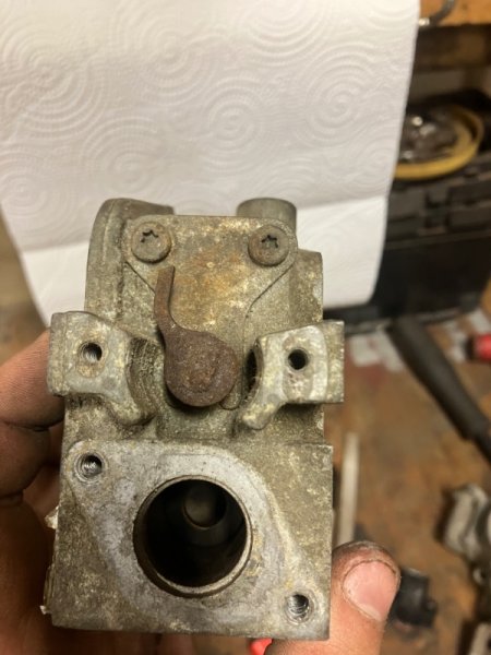
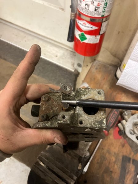
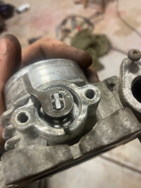
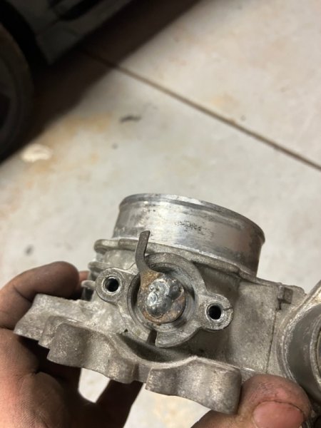
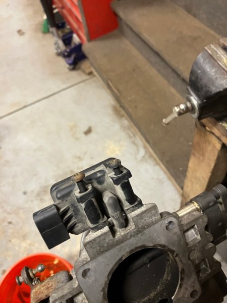
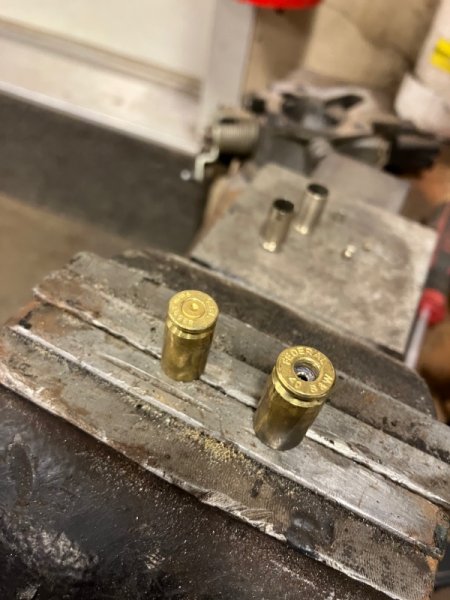
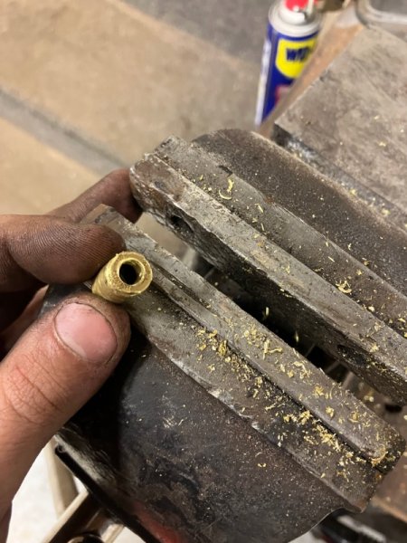
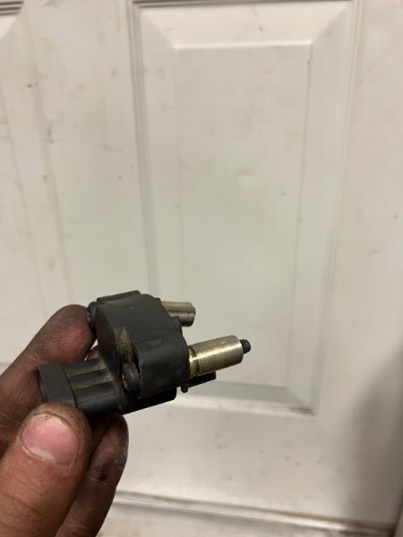
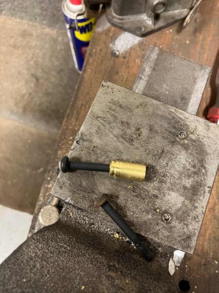
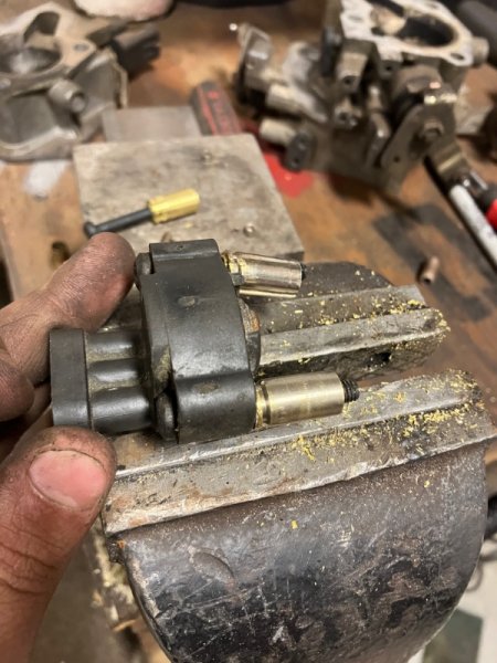
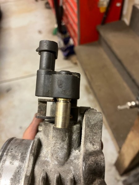
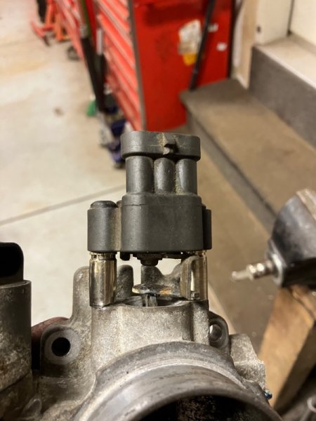
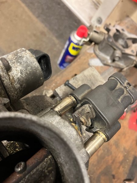
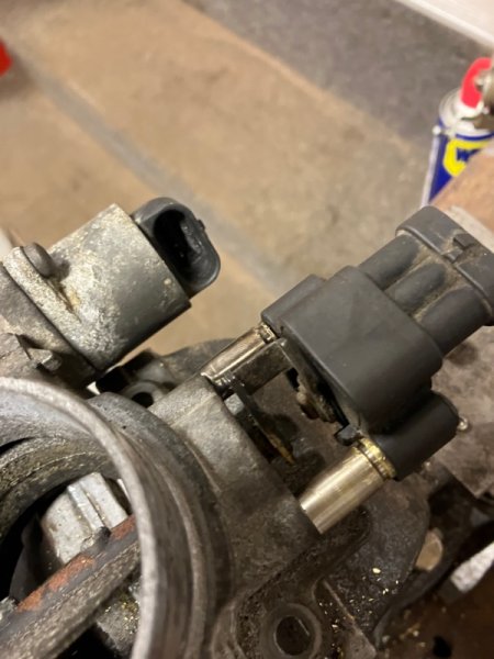
Alright so i’ve been preparing lately to drop an Ho motor in my 89, and so far the hardest thing has been finding a write up on the tps adaptor, the way I have done this modification requires no additional hardware, and uses unmodified Renix tps’s, while keeping the original amount of adjustment. Read Full Writeup Before Attempting To start you’ll need to take off the Tps connected to your renix throttle body. Next you will have to remove the arm attached to the throttle (see picture below) This can be difficult, I used screwdrivers to work it free, and then flattened the slight bends from removal in a vice. I then sized up the Renix arm I had just removed on the Ho Throttle body (where the Ho tps connects) I then filed down the shaft on the Ho Throttle body until the Renix arm fit ontop of it. (Note make sure the arm is clocked as shown, other positions will not work) Before After Then I tack welded it on to confirm it was in the correct location before burning it in completely After reaching this point you will need longer bolts and spacers to mount the Renix Tps to the Ho Throttle body. For bolts I found that the Ho map sensor bolts (located on throttle body) work perfectly. (see below) Finally For spacers I drilled holes in some 9mm Shell casings I had collected and they ended up being the perfect length without trimming (First remove primers by tapping them out, then drill) Finally bolt It all together and it should look something like this
-
Hey all, Here is the model and information you need to know about my Jeep. 1989 Jeep Comanche Eliminator, 4.0L Straight 6, Automatic Transmission, 2x4, I have A/C and cruise control. I have managed to complete my closed to open cooling system conversion. I did not spend a lot of money and I also did not go the cheapest route. I shouldnt have to replace any more water pumps or worry about cooling ever again. Here is a list of components that I bought: //////////////////////////////////////////////////////////////////////////////////////////////////// 2-Row Radiator - $100 https://www.amazon.com/gp/product/B01EVWTXLY/ref=oh_aui_detailpage_o09_s00?ie=UTF8&psc=1 Quality: 8/10 Functionality: 10/10 Comes with elbow and straight radiator cooling line fittings. Radiator Cap - $35 https://www.amazon.com/gp/product/B01F93S3E2/ref=oh_aui_detailpage_o00_s00?ie=UTF8&psc=1 Quality: 9/10 Functionality: 7/10 It is very hard to turn on and off the radiator. 4' of 5/8" Black Heater Hose - ~$15 total Autoparts store 4' of 3/4" Black Heater Hose - ~$15 total Autoparts store (2) 5/8" to 3/4" Hose Adapters - ~$15 total Autoparts store One Gallon of Concentrate Coolant - $15 Autoparts store One Gallon of Distilled Water - $3 High Flow Thermostat Housing - $33 http://www.hesco.us/products/7882/cooling-system/133247/hi-flow-thermostat-housing-hfth2#.WRuBvWjyuwU High Flow 180deg Thermostat - $19 http://www.hesco.us/products/7969/thermostats-and-housings/43013/hp--gmfordamcjeep-thermostat-180-degree-4364#.WRuIYGjyuwU Thermostat Housing Spacer - $37 http://www.hesco.us/products/7969/thermostats-and-housings/43017/thermostat-housing-spacer-hesths#.WRuIiWjyuwU High Temp Blue Silicone Gasket Maker - $12 Autoparts Store Hi-Flow Water Pump w/ Gasket - $87 https://www.4wd.com/p/flowkooler-high-flow-water-pump-natural-1747/_/R-GNLS-1747 Hose Clamps - ~$10 Autoparts Store 6' of 5/16" Hose for Radiator Vent - ~$10 Autoparts Store (1) 5/16-18 by ~2" long (1) 5/16-18 by ~1-1/4" long *Not exactly sure on length because I gave up on using the housing spacer (I will explain later) *The housing spacer and thermostat housing comes with gaskets. Total: ~$396 Well worth it, will never have a cooling issue. Works like a charm. My Jeep is preventing global warming from happening. //////////////////////////////////////////////////////////////////////////////////////////////////// A few pictures of stuff I bought... Start taking off parts... I had to take off the supports on top of the radiator, loosen the belt, and accessory fan. See photo below. NOTE: See the square rubber supports on top of the radiator? You need to reuse those. Take them off and put them on the new radiator so you do not forget... :doh: At this point I drained the coolant and took off all the hoses and transmission cooling lines. There is no pressure in the transmission lines so no fluid should leak out! Here is my old radiator taken out of the truck. This also shows the fitting types for the transmission lines. See the bottom elbow transmission fitting? My new radiator came with a replacement. The stock one is one piece and not a swivel fitting like the new fittings. You MAY have to grind, file, sand, etc. the diameter of the new elbow fitting so the plastic quick disconnect fitting will slide on the new fitting. Either that or you can file the plastic piece like I did. See below. ^^ That plastic piece goes on the elbow fitting ^^ I found that there was two holes that did not line up to support the radiator...Both sides. So I zip tied them on. Not too important since there are other brackets supporting the radiator on the top. First issue I found with the housing spacer... The belt comes pretty close the to lower housing bolt. See below. Also you can see two brass inserts. That is a 1/4" plug on the right (wrapped in teflon tape) and 3/16" plug on the left. Normally sensors go there on the newer jeeps. The Renix older jeeps have the sensors elsewhere. Second issue because of stupidity (Halfway my fault). Hardware store worker said the housing bolts were M8-1.25. They are not... They are 5/16-18. So I stripped out the holes and the bolts. I said screw the spacer and used original bolts. Bad luck for trusting the hardware store kid. :fs1: A little fabrication was needed for the radiator cap on the support bracket. It comes pretty close. Also, the vent hose is a 5/16" hose. I re-purposed my coolant reservoir bottle for my overflow tank. I forgot to take a picture but the two heater hoses go straight into the heater core. This shouldn't affect the A/C as the heater valve is open when the A/C turns on. This info is straight from the Jeep service manual I have. Heat comes out of the vents when the blower fan isnt on which is the only case which could be bad... Heat could build up without the blower fan on and melt/overheat things in the HVAC. Other helpful things to note: Make sure to put fan belt shroud/cover on before the new radiator is in. Make sure to put the rubber supports from the old radiator onto the new radiator. !!!!!!!! LET THE SILICONE CURE BEFORE FILLING THE SYSTEM WITH COOLANT !!!!!!!! Feel free to message me for any questions about my experience with this upgrade. :cheers: :rock on: :clapping: :waving: . :MJ 2: .
-
1988, Comanche, Pioneer 4.0 L / 2WD / Long Wheelbase Build date: Sticker Un-Readable Current Location: South East, Georgia, Atlanta Status: Still on the road - no rust - Work in Process Notes: I purchased this from a guy who had 3 Jeeps - Cherokee and 2 Comanches. I own two 95 YJs that I have tinkered with that my kids now drive. I wanted a truck and something else to tinker with so, I thought this would be a good option for me. The previous owner did a ton of mechanical work on the truck. I have stripped down the doors and windows and replaced all the rubber and fixed the vent windows, Replaced the big front bumper with a stock one. Had the Jeep painted. I am currently working on the stock flares and brackets.... you know the drill and plan to get the front window frame powder coated - the paint I tried did not work well. What's Next... Replace Carpet Lettering on Tailgate Rear Shocks - The Jeep has a 4 1/2" Rubicon lift but has the stock shocks on the rear which are topped out. Idle Sensor Tinker with a starting issue. Doesn't crank on the first try - much prefers the second turn of the crank. Bed Liner Hitch or Rear Bumper w/ Hitch A/C has a slow leak Spare Tire Holder Cabin Lights Reverse Lights Emergency Brake Tool Box and what ever else comes up or I think is necessary or desirable... Mostly - Just have fun. :cheers: This forum has been AWESOME. There are some very talented folks and the information that is shared really helps us weekend tinkerers. A BIG "Thank You" to everyone who shares.
-
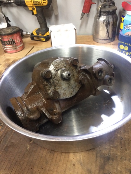
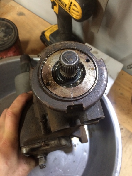
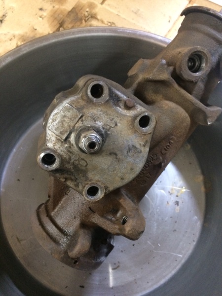
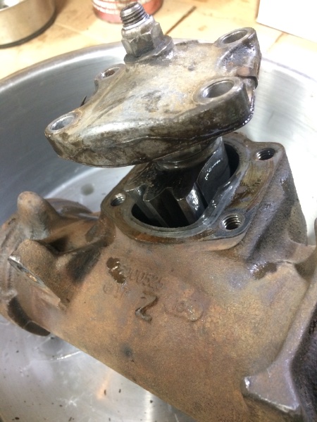
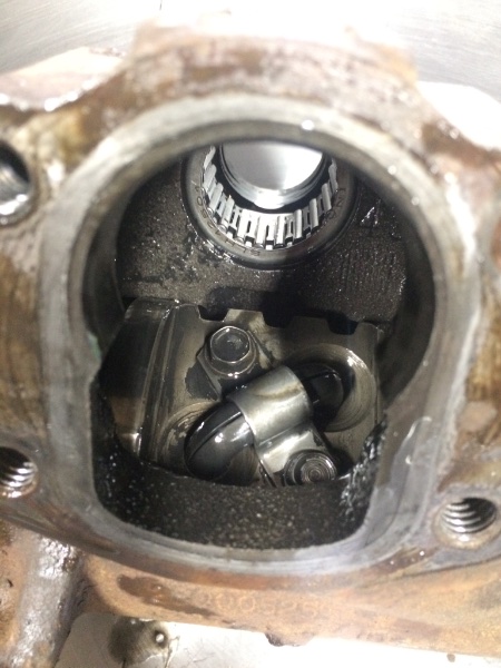
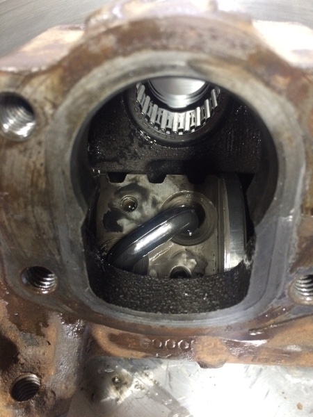
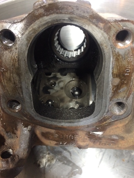
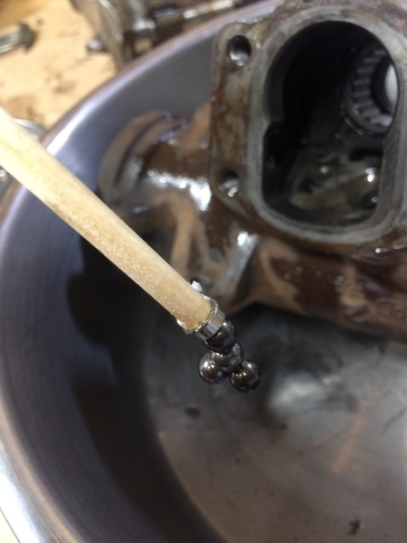
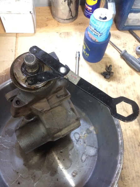
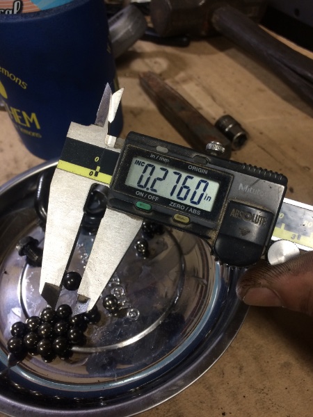
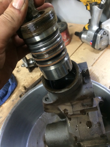
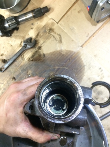
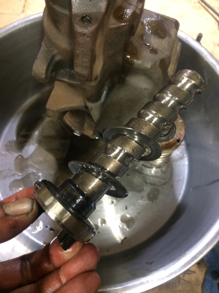
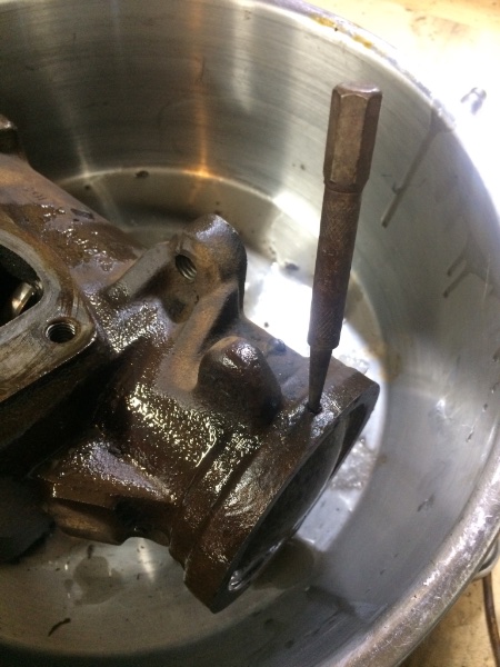
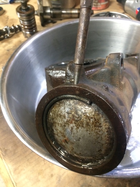
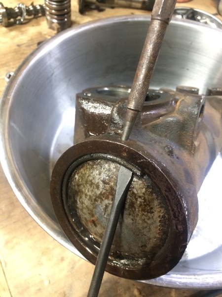
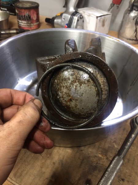
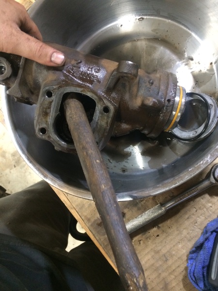
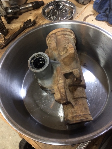
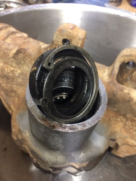
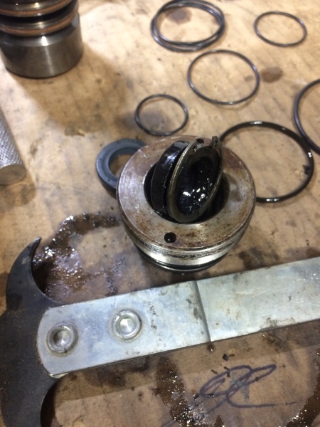
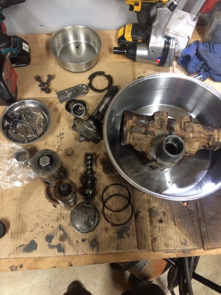
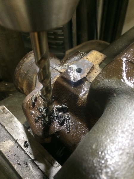
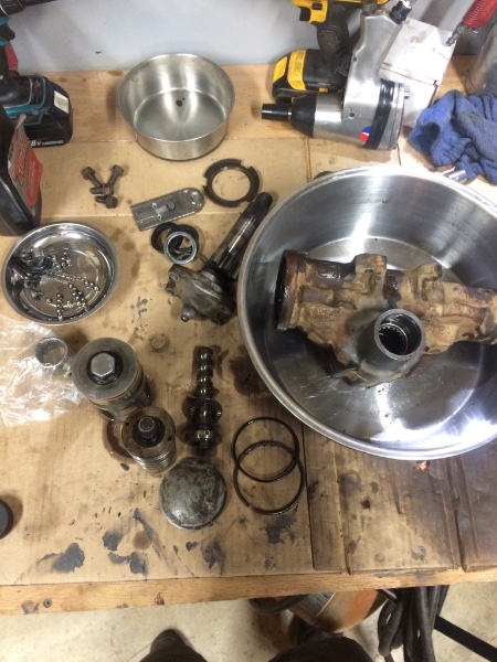
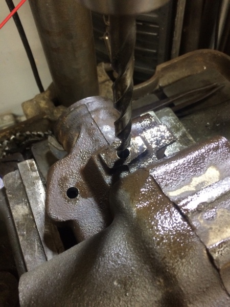
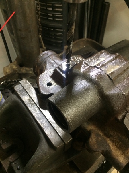
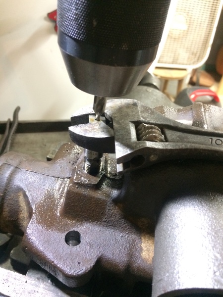
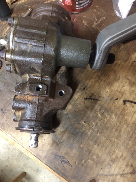
stock gear box cleaned Remove the four main bolts inside you’ll find the retaining clip on the ballbearing case the bearings travel side to side in I started out by pulling as many balls out as possible. I didn’t have a magnet on a stick so I glued a magnet to a stick. take the shaft side nut loose with a spanner I don’t remember the number of ball bearing. But did get a pic of the ball bearing size. In some of the case there is two different styles of bearings some chrome. And some dull finish. Mine had both styles alternating but the same size. use the cylinder to push the aluminum end cap out with a wooden hammer handle to pry with after removing the lock ring Remove the snap ring from the bottom . Pull the seal out and then press the old bearing out while you have it this far apart. My deal was melted from trying to get the pitman arm off. The spot to drill is pretty easy to find. The castings are flat in this area. drill into the veins of the box but not to far as to go through the other side. I used a 1/4 npt tap Then blow through the box a few times with compressed air and maybe oven pour some fluid through the holes and then hit it with some compressed air. When reassembling the most important part is the bearings on the worm screw. The need to be added evenly along the screw. I had to move it back and fourth a few times as I was dropping them in. I used a little grease to hold them inside the u shaped case And filled it up before sticking it back in place and fighting the bolts down if you get it back together and it moves for a moment then stops your bearings are out of wack. Take it back apart and make sure the bearings are in correctly
- 7 replies
-
- hydro assist
- steering box
-
(and 3 more)
Tagged with:
-
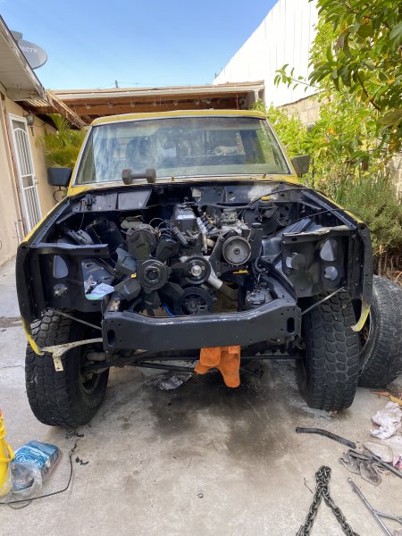
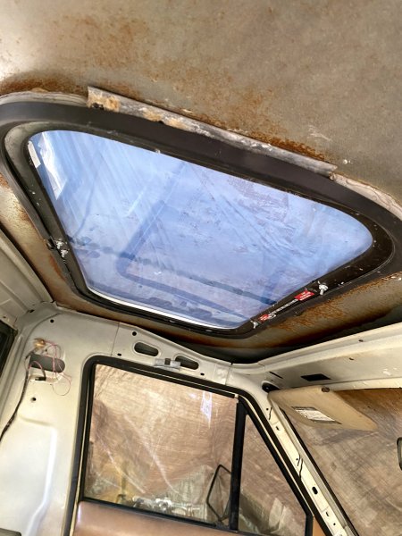
Hey guys! its been a while since I've been active on here and I wanted to give you guys an update on how mt build was going. So I've finally dropped the engine into the Comanche as of TODAY i have a few pics so ill start with that. ENGINE INSTALL: So I had decided to put the 4.0L I6 back into the car since the previous owner failed at doing a 4.3L v6 swap from a Chevy s10 (failed because he didn't put enough effort into the wiring and thus had several problems such as the entire gauge cluster not working, no high beams, and oh yeah, the thermostat was effed up and the heads blew) so once i finished absolutely gutting it, Ive been cleaning, painting, and buying parts for the new engine ever since. PLANS: I am going to finish up either this weekend or next by putting in the Aisin-Warner AW-4 four-speed automatic. I just need a transmission jack I need to swap the axles and do a whole suspension upgrade starting small with things like bushings and hardware. I plan on working my way up to stuff like shocks, coils, and eventually finding out how to get rid of leaf springs for something better. PROBLEMS: The. Seats. I have been looking up the bench seat to bucket conversion and taking the bench seat brackets seems not safe to me (probably because I'm an idiot lol). If anyone has any suggestions on that plz lmk. I've been looking at the threads as much as i can. The roof has been nothing but stress. I removed a god awful sunroof someone had put in even before the previous owner. I'm at the point now where if I see a Comanche at the junkyard i may just have to bring a generator and an angle grinder and take it.(also open to suggestions on this one please please) the heater core. on the donor xj i bought there was a really nice heater core and I messed it up trying to get it out. The bolts that hold it to the firewall were on too tight and when i began to pull it destroyed the plastic. For this I'm planning on trying out plastic welding it since the actual heater core is in excellent condition. just the plastic is messed up. The list goes on and on (as always). I appreciate all the elp you guys have been so far and I can't wait to keep adding stuff to my portfolio. I will try to post once a week but work and manche time take up most of my days. IMG_2334.HEIC IMG_2336.HEIC IMG_2337.HEIC
-
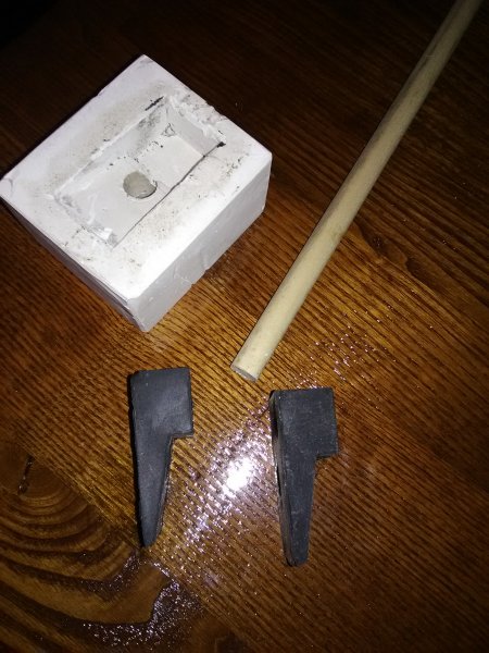
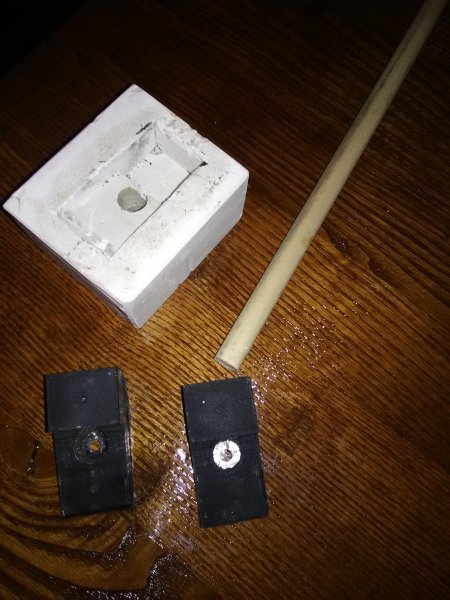
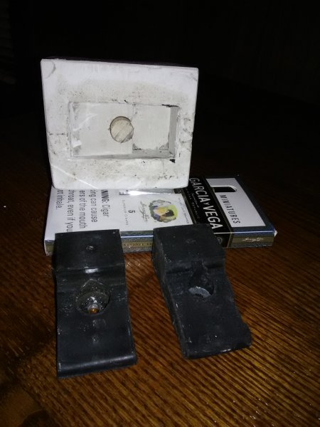
Since this has been a topic for a while I thought I would post my version for those that don't have access to a lot of special equipment. I had one good tailgate side insulator and one that was smashed.I removed the metal insert from the smashed one and cleaned it up. Made a plaster of paris mold of the good one. used silicon dielectric grease as a release on the rubber so it could be removed from mold, once mold has set up I drilled through original 3/16 to find center then removed original and drilled 1/2 hole through mold and inserted 1/2 dowel to support metal insert and used a small screw to hold insert to dowel, clamped dowel in vise to hold insert at proper height in mold, inside of mold and dowel get a lite coat of the dielectric grease as release, slowly pour FLEX SEAL LIQUID into mold till full I let it sit one week to fully cure. Both body side insulators were smashed so I cut one out of wood to form mold of it and poured that one today same process. This one turned out well and so far I have a $20 investment. I used FLEX SEAL LIQUID just cause its cheap but I believe windshield urethane would work as well and may set up faster. In pics original is on left FS part on right
-
Starting this post way late as I’ve owned the truck for 2 years almost and have done a lot to it already. So far I’ve done an engine swap (OEM motor blew #1&2 pistons out the block), new clutch, 4.5 inch lift, light bars, custom center console, window tint, paint, front and rear bumpers, ‘97 Cherokee mirrors, front and rear LED pods, rock lights, exhaust, LED front lights, converting everything to LED, clear turn signals and side markers. I still have a lot left in store for this rig such as a new 4.0l HO that I’m building with a voodoo cam (262/268), Dana 44 or Ford 9inch rear axle swap, and regear both axles to 3.73’s with ARB lockers, cromeolly axles, an 8 inch lift, slip yoke eliminator and longer drive shafts, bigger tires, custom rock sliders and fender flares, paint, new rear glass, front driver seat, new dash, floor pans, white face gauges. Not doing anything too too crazy as it will be a daily driver for a minute but any advice y’all got on parts or easiest and cheapest way to do it but still quality let me know thanks!!
-
DIY convert from closed to open cooling. This Write up is how I converted from closed to open cooling. You may choose other parts to achieve the same end result. I am converting because I am tired of messing with the pressure bottle, to remove the heater flow valve, and replace old hoses. Parts: Radiator with filler neck $82.57 * Part number: CU1193 Radiator cap $24.99 * (I bought a fancy cap with built in thermometer.) Part number: 2471S 2 Gallons antifreeze coolant $14.99 ea ($24.98 for 2) *** Item number: 7020022 10' 5/16 hose $19.90 *** $1.99 per foot Item number: 5194083 4' 3/4 heater hose $5.56 *** $1.39 per foot item number: 5192978 4' 5/8 heater hose $5.56 *** $1.39 per foot Item number: 5192951 Two 3/4 to 5/8 hose adaptors $2.99 ea ($5.98 for 2)*** Part number: 80424 A junkyard radiator bottle (I think mine was from a ZJ or WJ dad snagged it for me) Total conversion cost: $169.54 + S&H and tax Optional Parts: Later model thermostat housing with temperature switch new water pump Dual Fan Controller Second Electric fan for dual conversion Wire Relay or Fan Controller Power Switch MJ or XJ 2.5L Radiator Bottle $16.99 ** Part number: 52003213 MJ or XJ Bottle Cap $7.97 ** Part number: J3223202 Ordered from: Amazon.com * Morris4x4.com ** Advanced Auto Parts *** Tools: Gloves Safety glasses Knife or box cutter Phillips and flat head screwdrivers Bucket T-25 T-30 8mm Socket and or wrench 10mm Socket and or wrench Getting Started Start by draining out the old radiator fluid, removing the upper and lower radiator hoses, fan temperature switch, and if you have an auto transmission the transmission cooler lines from the radiator. Use an 8mm socket or wrench to remove the electric fan and clutch fan shroud. The radiator support is held on by several bolts 10mm and T-25 or T-30 (sorry mine where all stripped before I started not exactly sure the actual size). The bolts removed connect the support to the frame and front clip, then they are all out remove the radiator support. The radiator should come out without much fuss. With the radiator out of the way now would be the perfect time to convert to Dual electric fans and replace the water pump. Sadly I was running out of time due to fighting with stripped bolts so i was not able to do ether.... Depending on the radiator you get you may not need to change the thermostat housing. My thermostat housing is from a later model XJ, and can use a temperature switch. However the radiator I purchased has the hole for the fan temperature switch. Remove the 3/4 hose and the 5/8 hose from the thermostat housing and the water pump. Remove the old coolant pressure bottle and the hoses going to the heater core. Cutting the hose may be needed. The new hoses will need to be adapted from 3/4 to 5/8, the reason for this is the thermostat housing outlet is 3/4 connecting to the heater core that is 5/8, and the heater core outlet is 3/4 connecting to the water pump inlet that is 5/8. After all the old hoses are removed take your new 3/4 and 5/8 hose and route it however you like, then measure where to cut the hose in half. Use the 3/4 to 5/8 adapters as needed. Again the hose routing is: 3/4 from thermostat housing 3/4 to 5/8 adapter 5/8 to heater core inlet 3/4 from heater core outlet 3/4 to 5/8 adapter 5/8 to water pump The new coolant bottle is the next challenge. I ordered a 2.5L MJ/XJ coolant bottle that should fit on the drivers side fender, I will likely need to go back to a cone air filter to make room for it. Till I decide for sure what bottle I am sticking with I used one from a Junk yard Jeep and slightly modified it to work. I had to remove the old pressure bottle "shelf" to make room. I used a self tapping screw to attach the radiator bottle to the back of the engine bay where the old bottle was located. I routed the 5/16 hose around the back of the bottle and used the heater hoses as a bridge, ending where the radiator filler neck will be. Install the new radiator and reconnect the upper and lower radiator hoses. Reattach the radiator support. Connect the Coolant bottle hose to the filler neck. For good measure I zip tied all the new hoses in place. Fill the radiator system with 12 quarts (3 Gallons) of coolant. Must be a 50/50 mix, you can use pre-mix or concentrate with distilled water. you may not be able to fit all 12 quarts as there will likely be some coolant still in the engine. Bleed the air out of the system, Renix engines have a coolant temperature sensor on the back of the head accessible from the engine compartment. Clean up and all done Prior to this conversion My Jeep would boil over in 20 minuets and interstate travel was a no go. Now the temperature has yet to pass the 210 mark while traveling 75 mph on the interstate. A side note, my A/C seems to be blowing cooler as well now....
- 18 replies
-
I just picked up a 2wd 88 eliminator and id like to do a 4x4 conversion. What all will i need to do to accomplish this task? I believe all i will need will be a front axle trans and matching t-case all linage involved a bell housing and a front driveshaft. Now this is my plan: I'd like to do a Dana 30 with 4:10 gear ratio, a bell housing from a late 93+ Cherokee with the external slave, an AX15 trans with matching NP231 t-case 23 spline, a new center console to account for the 4x4 shifter lever, and a custom front driveshaft. Now am i able to keep my original rear axle or will i have to swap that as well, And if i can keep it how can i change it to make it work with the 4:10 gear ratio i'm seeking? Let me know if i'm missing or forgetting anything. I'm also looking to give it a 3"-4.5" lift. With that lift what size tire would you recommend? I'm thinking of running 35's. :driving:
