


cruiser54
-
Posts
9413 -
Joined
-
Last visited
-
Days Won
14
Content Type
Profiles
Forums
Gallery
Everything posted by cruiser54
-

replacement EGR for renix 4.0
cruiser54 replied to 10thta's topic in MJ Tech: Modification and Repairs
I don't think that's a good test. Most important is that the pintle seals to the body of the eGR with no vacuum. You can test by blowing on it with your mouth. -
About 700 RPM
-
HELP! Wiring issue after putting dash back in
cruiser54 replied to Prestin_xj's topic in MJ Tech: Modification and Repairs
CRUISER'S MOSTLY RENIX TIPS IMPROVING THE INSTRUMENT PANEL GROUND NOVEMBER 17, 2015 SALAD 27 COMMENTS EDIT The ground point for the complete instrument cluster on your XJ or MJ is located up under the driver’s side dash. If you lay on your back and look up under there with a flashlight, without wearing a hat, you will see a black wire attached to a shiny piece of metal almost directly above the hood release knob. The screw will have either a ¼” or 5/16″ head on it. This ground point is responsible for handling the ground circuit for the following items: Dome lamps, seat belt and key warnings, transmission power/comfort switch, wiper switch, headlamp switch and delay module, fog lamp switch, cargo lamp switch, all instrument panel grounds and illumination, power windows and door locks, cruise control dump valve, and a few more things. The problem is that where the ground point is located does not share good contact with the chassis where the ground should be. The solution is simple: Make up a jumper wire with #10 gauge wire about 10″ long. On one end, crimp on a ¼” round wire terminal. On the other end, crimp on a 3/8″ round wire terminal. Remove the screw from the existing ground wire and attach the small terminal of your jumper so that the original wire and your new jumper share the same attaching point, one over the other. Look above the driver’s side plastic kick panel just forward of the top of the hood release knob. You will see an 8mm stud there. Attach the large terminal end there with a washer and nut over it tightened securely. Use a coating of OxGard at all ground contact surfaces when attaching the screw and nut. **Special note for Comanche owners: Make your jumper wire 12″ long and attach it on the driver’s side kick panel close to the fusebox on the 8mm stud.** -
Struggling to get parts in Oz
cruiser54 replied to Aussie's topic in MJ Tech: Modification and Repairs
Everything is the same as 4 door XL through 1995. except that thing for the rear bumper. -
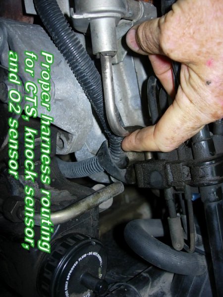
Here ya go: CRUISER'S MOSTLY RENIX TIPS RENIX TPS ADJUSTMENT OCTOBER 30, 2015 SALAD 198 COMMENTS EDIT Before attempting to adjust your TPS, there are a few things that need to be done. Be sure the throttle body has been recently cleaned. It’s especially important that the edges of the throttle butterfly are free of any carbon build-up. With the KEY OFF, and using the positive (red) lead of your ohmmeter, set on the lowest scale, probe the B terminal of the flat 3 wire connector of the TPS. The letters are embossed on the connector itself. Touch the black lead of your meter to the negative battery post. Wiggle the wiring harness where it parallels the valve cover and also over near the MAP sensor on the firewall. If you see more than 1 ohm of resistance, or fluctuation in your ohms reading, some modifications to the sensor ground harness will be necessary. The harness repair must be performed before proceeding. It is covered in detail in Tip 6. TPS ADJUSTMENT FOR ENGINE ISSUES Both Renix manual and automatic transmission equipped XJs and MJs have a flat three-wire connector to the TPS which provides data input to the ECU. The three wires in the connector are clearly embossed with the letters A, B, and C. Wire “A” is positive. Wire “B” is ground. DO NOT UNPLUG THE CONNECTORS! KEY ON, measure voltage from “A” positive to “B” ground by back-probing the connectors. Note the voltage reading–this is your REFERENCE voltage. KEY ON, back-probe the connector at wires “B” and “C”. Measure the voltage. This is your OUTPUT voltage. Your OUTPUT voltage needs to be seventeen percent of your REFERENCE voltage. For example: 4.82 volts X .17=.82 volts. Loosen both T-20 Torx screws attaching the TPS to the throttle body and rotate the TPS until you have achieved your desired output voltage. Tighten the screws carefully while watching to see that your output voltage remains where it is supposed to be. If you can’t achieve the correct output voltage, replace the TPS and start over. Sometimes, after adjusting your TPS the way outlined above, you may experience a high idle upon starting. If that happens, shut the engine off and reconnect your probes to B and C. Start the engine and while watching your meter, turn the TPS clockwise until the idle drops to normal and then rotate it back counterclockwise to your desired output voltage. TPS ADJUSTMENT FOR AUTOMATIC TRANSMISSION ISSUES Renix automatic transmission-equipped XJs and MJs have a TPS with two connectors. There is a flat three-wire connector, same as the manual transmission vehicles have, and it is tested the same as outlined above—FOR ALL ENGINE MANAGEMENT RELATED ISSUES. However, the automatic TPS also has a square four-wire connector, clearly embossed with the letters A,B,C, and D. It only uses three wires and provides information to the Transmission Control Module. THIS SQUARE FOUR WIRE CONNECTOR IS USED FOR TRANSMISSION/SHIFTING RELATED ISSUES ONLY. First off, DO NOT UNPLUG THE CONNECTORS! KEY ON, measure voltage between “A” positive and “D” ground by back-probing the connector. Note the voltage. This is your REFERENCE voltage. Back-probe the connector at wires “B” and “D”. Measure the voltage. This is your OUTPUT voltage. Your OUTPUT voltage needs to be eighty-three percent of your REFERENCE voltage. For example 4.8 volts X .83=3.98 volts. Adjust the TPS until you have achieved this percentage. If you can’t, replace the TPS and start over. So, if you have an automatic equipped XJ your TPS has two sides–one side feeds the ECU, and the other side feeds the TCU. For those with a MANUAL TRANSMISSION–the TPS for the manual transmission XJs is stupid expensive. You can substitute the automatic transmission TPS which is reasonably priced. The square 4 wire connector is just not used.
-
replacement EGR for renix 4.0
cruiser54 replied to 10thta's topic in MJ Tech: Modification and Repairs
Where is the original leaking vacuum? -

-

-

-
Oxygen Sensor heater issues
cruiser54 replied to big66440's topic in MJ Tech: Modification and Repairs
How old are the plugs and what brand? Distributor cap and wires? Ever done this? http://cruiser54.com/?p=131 -
New ign. coil or origonal Renix made in France?
cruiser54 replied to EUREKA's topic in MJ Tech: Modification and Repairs
I like it. -
Oxygen Sensor heater issues
cruiser54 replied to big66440's topic in MJ Tech: Modification and Repairs
Actually, that's what usually fails. That sensor must have an excellent ground. Check yours with a meter at the sensor plug, harness side. You have completed Tips 1,3,4, and 5 at my website, right? -
Ever visited my website? Tips 1 through 5 first chance you get. Or maybe before doing anything else.
-
Winter running temps
cruiser54 replied to eaglescout526's topic in MJ Tech: Modification and Repairs
Mopar stat? -
A dual diaphragm booster would be a better way to go for more braking power. The 44 is an expensive rearend to convert to disc.
-
Just get a set of the correct injectors. Rebuilt. I have a reliable source for you and they are an upgrade.
-
New ign. coil or origonal Renix made in France?
cruiser54 replied to EUREKA's topic in MJ Tech: Modification and Repairs
But, are the Bosch ones made in China? -
New ign. coil or origonal Renix made in France?
cruiser54 replied to EUREKA's topic in MJ Tech: Modification and Repairs
Keep the Renix. No CRAP. Chinese Replacement Auto Parts. -
No downside. except emissions visual inspection maybe? Will run just fine.
-
Cylinder head thermostat housing boss broken
cruiser54 replied to fz1p5c's topic in MJ Tech: Modification and Repairs
You bet. The 4.0 didn't use mumblemeter measurements. -
Cylinder head thermostat housing boss broken
cruiser54 replied to fz1p5c's topic in MJ Tech: Modification and Repairs
How come you're going metric? -
3 connectors at the end of the injector rail
cruiser54 replied to Vandenborg1's topic in MJ Tech: Modification and Repairs
-
Cylinder head thermostat housing boss broken
cruiser54 replied to fz1p5c's topic in MJ Tech: Modification and Repairs
One of my Mom's favorites also. -
Cylinder head thermostat housing boss broken
cruiser54 replied to fz1p5c's topic in MJ Tech: Modification and Repairs
4.os have a head bolt that does that!! Permatex #2 seals the threads. -
Cylinder head thermostat housing boss broken
cruiser54 replied to fz1p5c's topic in MJ Tech: Modification and Repairs
I like option 2.