Search the Community
Showing results for tags 'ground'.
Found 3 results
-
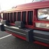
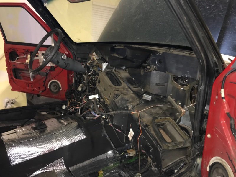
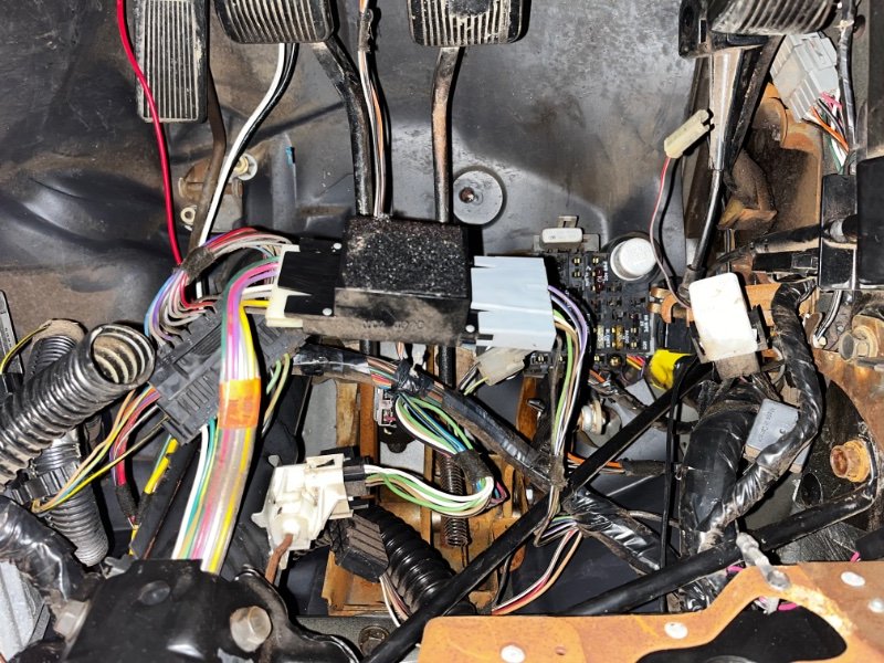
 HELP!! In the process of putting my dash back in my 88’ mj. I completely gutted the interior to swap in a different dash and do the heater core. Must’ve forgot some wiring somewhere when putting the dash back in but I have no idea where. Trying to charge the battery, and when the tender is turned on this is what happens when I turn the key on and off. When the key is off, the ac compressor clicks. When the key is on the compressor stops clicking and the fuel light/cluster gauges pulse along with the seatbelt light and radio screen. And one of the circular relays under the dash starts clicking. Gauge cluster and climate control lights also won’t come on. Also does different stuff when I have the headlight switch pulled out. I’m thinking some kind of ground but like I said I’m lost. Everything seems to be plugged back in… Any ideas?? 😔
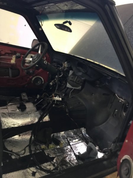
-
I will say I had a low idle that was hovering around 400-500 and going through Cruiser54's TPS adjustment and ground refresh, she is idling around 750 now in drive. I already did the engine and chassis ground upgrades but I did not know about the TPS,CTS,IAT, and ECU ground wires that are located in the wire harness by the firewall. Cleaned the throttle body, soldered the five ground wires together (there was orignally a crappy clamp) and adjusted the TPS to the correct spec. Idles like a champ. Before I soldered, I did the ohm's test for the three prong connecter and I had varying resistance. So, after soldering I tried again and that problem was solved. I still have a ~2 ohm reading which is a little high. But nothing to worry about I don't think. When I did the TPS adjustment, my reference voltage was 5.02 V and I adjusted to where the output voltage was .85 V. Cruiser’s Renix Sensor Ground Test This sensor ground circuit affects the CTS, TPS, IAT, MAP, ECU and diagnostic connector grounds. It’s very important and not something to overlook in diagnosing your Renix Jeep as it is common for the harnesses to have poor crimps causing poor grounds. If any or all of the sensors do not have a good ground, the signal the ECU receives from these sensors is inaccurate. Set your meter to measure Ohms. Be sure the key is in the OFF position. Using the positive (red) lead of your ohmmeter, probe the B terminal of the flat 3 wire connector of the TPS . The letters are embossed on the connector itself. Touch the black lead of your meter to the negative battery post. Wiggle the wiring harness where it runs parallel to the valve cover and also near the MAP sensor mounted on the firewall. If you have an 87 or 88 with the C101 connector mounted on the firewall above the brake booster, wiggle it, too. You want to see as close to 0 ohms of resistance as possible. And when wiggling the harnesses/connectors the resistance value should stay low. If there is a variance in the values when wiggling the wires, you have a poor crimp/connection in the wiring harness or a poor ground at the engine dipstick tube stud. On 87 and 88 models, you could have a poor connection at the C101 connector as well. Revised 06/12/2012 Put this together to simplify the TPS testing and adjusting on 87 to 90 Renix Jeeps. There are other procedures out there but half of them are wrong and don't separate out driveability testing from transmission testing like these do. Remember: You must adjust a TPS after replacing it on a Renix Jeep, unlike the later models. RENIX TPS ADJUSTMENT Before attempting to adjust your TPS be sure the throttle body has been recently cleaned. It's especially important that the edges of the throttle butterfly are free of any carbon build-up. IMPORTANT NOTE: Using the positive (red) lead of your ohmmeter, probe the B terminal of the flat 3 wire connector of the TPS . The letters are embossed on the connector itself. Touch the black lead of your meter to the negative battery post. If you see more than 1 ohm of resistance some modifications to the sensor ground harness will be necessary. The harness repair must be performed before proceeding. I can provide an instruction sheet for that if needed. MANUAL TRANSMISSION: RENIX manual transmission equipped XJs have a three-wire TPS mounted on the throttle body. This manual transmission vehicle TPS provides data input to the ECU. The manual transmission TPS has three wires in the connector and they're clearly embossed with the letters A,B, and C. Wire "A" is positive. Wire "B" is ground. Key ON, measure voltage from "A" positive to "B" ground by back-probing the connectors.. Note the voltage reading--this is your REFERENCE voltage. Key ON, back-probe the connector at wires "B" and "C". Measure the voltage. This is your OUTPUT voltage. Your OUTPUT voltage needs to be seventeen percent of your REFERENCE voltage. For example: 4.82 volts X .17=.82 volts. Adjust the TPS until you have achieved this percentage. If you can't achieve the correct output voltage replace the TPS and start over. AUTOMATIC TRANSMISSION: RENIX automatic transmission equipped XJs have a TPS with two connectors. There is a flat three- wire connector, same as the manual transmission vehicles have, and it is tested the same as the manual transmission equipped vehicles--FOR ENGINE MANAGEMENT RELATED ISSUES. However, the automatic TPS also has a square four-wire connector clearly embossed with the letters A,B,C, and D. It only uses three wires and provides information to the Transmission Control Module. Key ON, measure voltage between "A" positive and "D" ground. Note the voltage. This is your REFERENCE voltage. Back-probe the connector at wires "B" and "D". Measure the voltage. This is your OUTPUT voltage. Your OUTPUT voltage needs to be eighty-three percent of your REFERENCE voltage. For example 4.8 volts X .83=3.98 volts. Adjust the TPS until you have achieved this percentage. If you can't, replace the TPS and start over. So, if you have an automatic equipped XJ your TPS has two sides--one side feeds the ECU, and the other side feeds the TCU. If you have TRANSMISSION issues check the four-wire connector side of the TPS. If you have ENGINE issues check the three-wire connector side of the TPS. For those with a MANUAL TRANSMISSION--the TPS for the manual transmission XJs is stupid expensive. You can substitute the automatic transmission TPS which is reasonably priced. Revised 11-28-2001
-
 Hello all, i bought my 1st comanche yesterday and all of the signals DID work except for the front left.. it would stay on continuously no matter what, aslong as the headlights were on, and the hazard lights wouldnt do anything... now today NONE of the signals work, and the front left still stays completely illuminated aslong as the headlights are on, and the hazards also still don't work, and now i have noticed the interior arrow lights no longer light up and no longer makes the clicking noise when you turn. Ive ripped right into the dash, check all of the relays, fuses appear to be good, etc if anyone can give me some helpful advice on how to get my signals working it would be greatly appreciated Thanks fellow Comanche owners!!