Salvagedcircuit
-
Posts
1381 -
Joined
-
Last visited
Content Type
Profiles
Forums
Gallery
Everything posted by Salvagedcircuit
-
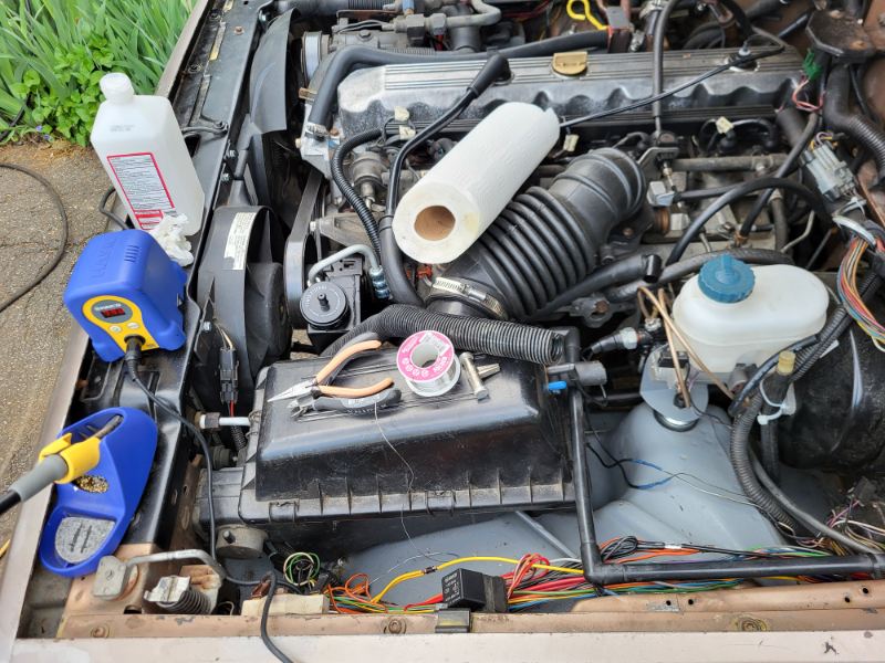
I don't know about parts sources, but I posted some photos of the turbo diesel engine bay in this post, which may be useful.
-

Custom Gaskets for HVAC
Salvagedcircuit replied to H3ADBANG4L1F3's topic in MJ Tech: Modification and Repairs
Those look good! I'm not in the position where I need one yet, but when I do, I know who to contact! -
1992 Jeep Comanche "Maria"
Salvagedcircuit replied to MariaManche's topic in Member Projects: Your Comanches
Nice -
Excellent work!
-
It is possible that this is not really an issue and amc / renault treated the flasher as a "temporary state" and did not compensate for the flasher on the flasher circuit. The new electronic flasher is substantially louder than my thermo flasher and I will be reducing the taillight / marker light current load when I go to LEDs, which should be soon enough. I'll update this here again when that time comes. Thanks again everybody, special thanks to Ohm!
-
The Alabama Turbo Diesel
Salvagedcircuit replied to ThreeComanches's topic in Member Projects: Your Comanches
Hahaha! That's excellent. Northern NH is such a time capsule, It's great. Enjoy the 100 imacs. How do you use all 100 at the same time? a Beowulf cluster? -
It is possible that this is not an actual issue. +-0.5v is not the end of the world. I do wonder if other folks have +- 0.5v on their cigarette lighter when the flasher is enabled. If anyone tests, be careful when you probe, I've shorted (2) 15a fuses by not being steady with my probes. I posted about this issue a few months back, but I did not realize it impacted multiple circuits. It seems @eaglescout526 had a similar blinking issue. I wonder if it's normal for renix XJ/MJs.
-
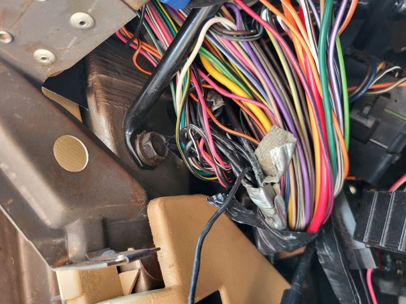
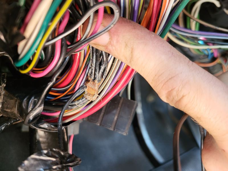
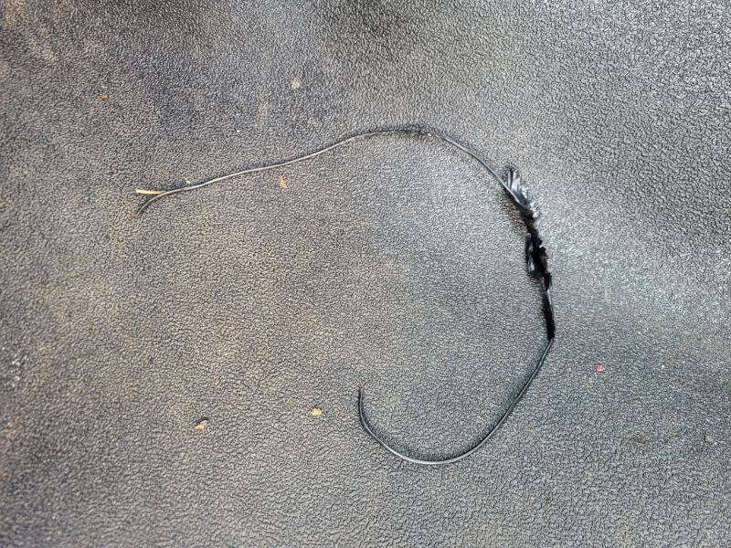
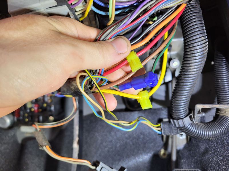
I was able to access the portion of the wire loom from the 12awg to the 18awg wire that was designated for the radio. The wire melted together with several other circuits along the wire harness behind the dash. I cut the wire at the lovely (7) 18awg wire-to-12awg duct-tape crimp and removed the melted wire from the wire loom. I was just able to get to the wiring harness by removing the front cowl, cutting some zip ties and finagling the wire loom into the gauge cluster area. Unfortunately, despite removing this melted wire, the same problem persists. Nothing changed, it's still +- 0.5v and +- 0.3v on the same circuits as above. I tested with other turning signal flashers and the same results occur.
-
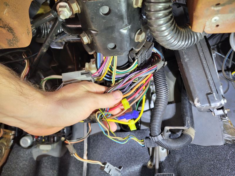
Thanks. I checked these last night. both connectors are clean and don't look melted. However, the (3) ghost-crimped wires were attached to 3 of the wires on these two connectors. I have since soldered them up and repaired them properly I am currently removing the front most dash cowl to try and access the wireloom that goes to the radio and inspect for damage. The phillips screws they used are really hard to get to, especially the driver side one. I'm hoping to cut the wire zip-ties that hold on the wire loom and move them down to the gauge cluster area where I should then be able to inspect the wires individually.
-
When the key is in the accessory position and the turning signal is on: +- 0.5v -Blower Motor -Turn B/U -Radio +-0.3v -power accessory -trans fuse -gauges When the key is in the engine-on position and the turning signal is on: +- 0.5v -Blower Motor -Turn B/U -Radio +-0.3v -power accessory -trans fuse -gauges *voltages are referenced to G102 gnd location, below steering wheel.
-
I finished soldering up the ghost crimps and I tried some newly produced thermal flashers. I noticed that the voltage drop was about 0.5v now instead of about 1v with my old thermal flashers. The newly manufactured flashers also blink rapidly but at least consistently. I'm going to go grab an electronic led flasher and see if that resolves my issue. Is it possible the blinking issue is related to the column turning signal switch?
-
This I did not know. Thanks. I'll dig around a bit there. I'm trying to avoid removing the whole dash if possible.
-
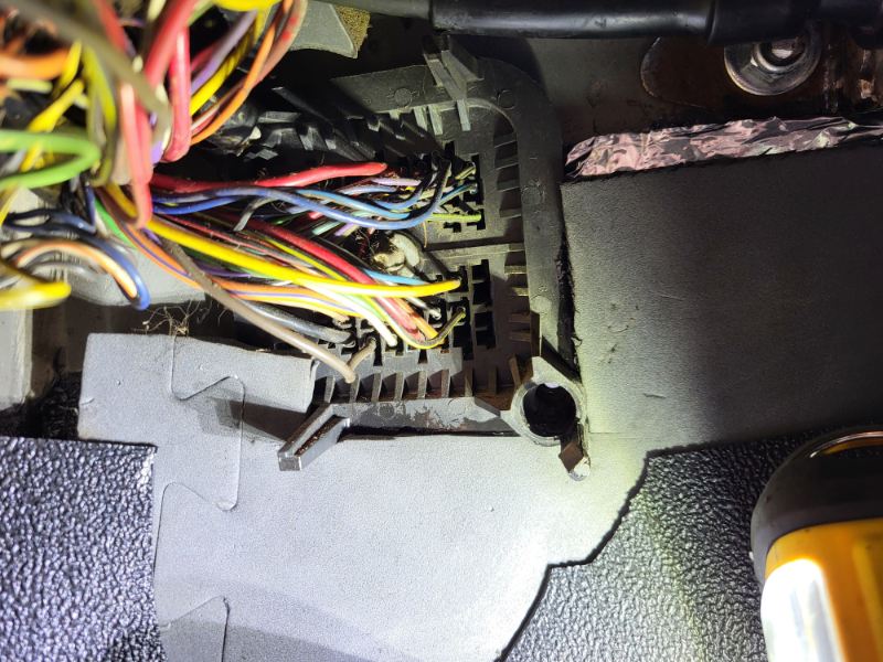
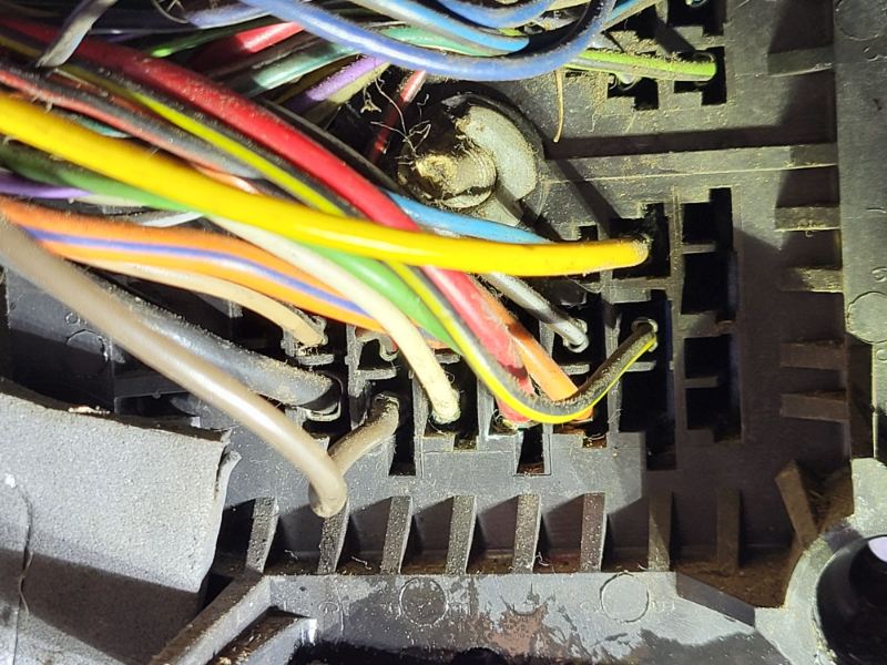
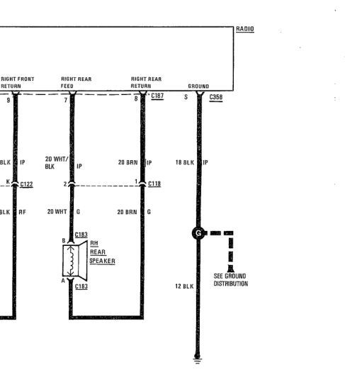
Thanks for your input! There is a 12awg wire at what looks like H4 to me and there is a brown/blk trace wire at g4. The black wire measures 0.2ohm to c103, which is good. no signs of melting or corrosion near the connector in the bulkhead. No signs of melting or corrosion on the back of the fuse panel either. There was a considerable amount of dust / foam around the two, so I blew out the whole area with compressed air. It seems that source of the 12awg gnd is in good shape, I just have to find out where the 12awg splits into an 18awg gnd wire. that should be the location of most carnage. Any idea where to find point G? (page 57 of the electrical manual) One other thing I noticed, are there supposed to be (3) ghost crimps on the wiring harness that goes to the steering column? Edit: I have since soldered these up and insulated.
-
What is G4_C100? I know C100 is the bulkhead. What is G4? Thanks.
-
I have been having a strange issue where my radio LCD backlight blinks whenever my turning signal is active. The cigarette lighter and radio are on the same circuit, so I measured the 12v rail. When the vehicle is off, the 12v rail fluctuates from 11.3v to 12.5v with the turning signal, and that correlates directly to the radio lcd backlight. I have tested: -Headlights. Issue persists regardless if I have LED or halogen front headlights. I have rear halogen bulbs. -Cab lights. Issue persists regardless if I have the LED cab and footwell lights installed. -Radio / clock illumination relay. Tests fine with 12v psu. -Radio. Removed, makes no difference. -Checked Fuses. Etr fuse is fine. -Soldered and repaired the ~30 duct-tape crimps in the engine bay. -Have not disturbed the C101 (because its mostly engine related wiring). Details: -I have a base comanche that never had a radio. No headlight sentinel either. Previous owner butchered the radio harness. I re-wired it and I believe it is correct, but I may be wrong. no wires are bridged to the radio connector, each wire is one conductor. -The original ground wire for the radio was melted badly (wire jacket missing in sections). I insulated it with electrical tape and ran a new ground from G102 ground location (below steering column). My dash fascia is currently apart and I'm trying to trace any potential other damage this wire caused. -The radio LCD backlight is operating correctly. The lcd backlight turns on when the vehicle is on and when the headlights are on, dims with the dimmer switch, which is correct as per the manual. When headlights are on and the radio backlight is out (dimming set to 0), the Cigarette lighter measures 14.5v. -The flashers seem to still work, but either continue to work quietly or start flashing fast then go silent and stop working completely. Possible culprits: -wiring harness -column turning signal switch? -flasher? I am looking over the 88 electrical wiring diagrams. If anyone has any input, I would gladly appreciate it. Thanks!
-
cab corners are here :)
Salvagedcircuit replied to Pete M's topic in MJ Tech: Modification and Repairs
Aww man, this is gonna save so many comanche's! KeyParts is on a roll! -
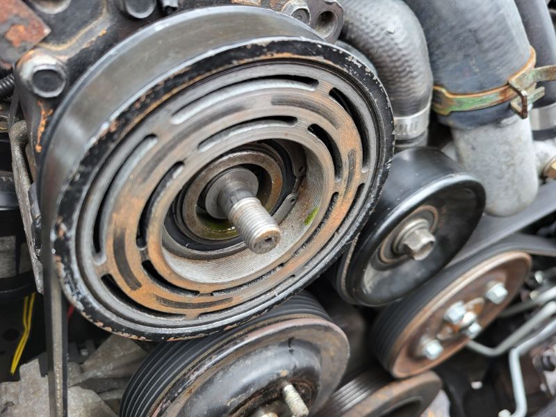
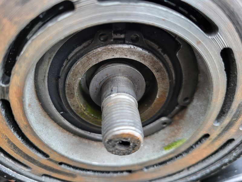
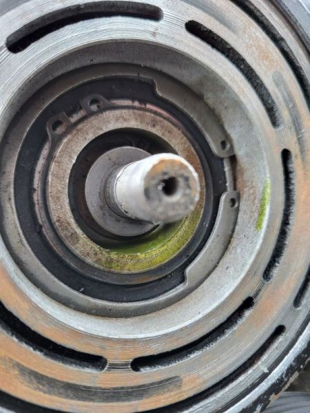
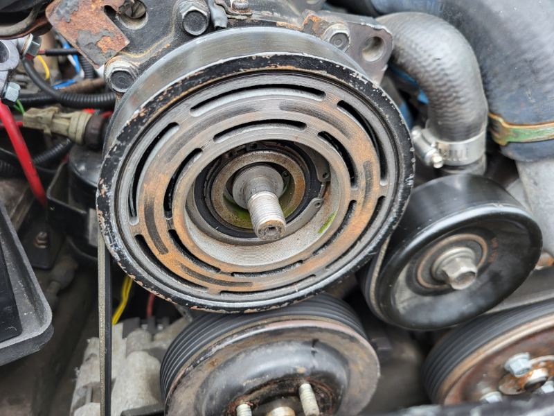
AC Compressor clutch plate oil?
Salvagedcircuit replied to Salvagedcircuit's topic in MJ Tech: Modification and Repairs
it is r134a. thanks for the input. I'm guessing I can't use the system as is, even though it is cooling. I'd love to just add more oil to the compressor and use it, but I have a feeling that is not going to be an adequate solution here. The system recharged and held from last night. I'm still getting cool air. I at most had the ac running in 5minutes intervals during testing. -
I finally was able to get AC functional in my comanche. The shim spacing was incorrect on the compressor clutch plate and the plate was unfortunately warped. I filled my system up with the clutch excited externally and actually had cold air in the cab. Today, when removing the clutch plate for the 4th time to remove the unneeded 5-thou shim, I noticed there was oil in the front face of the clutch. Does anyone know if this is normal? I'm guessing the compressor is leaking somehow. What does it mean? Thanks
-
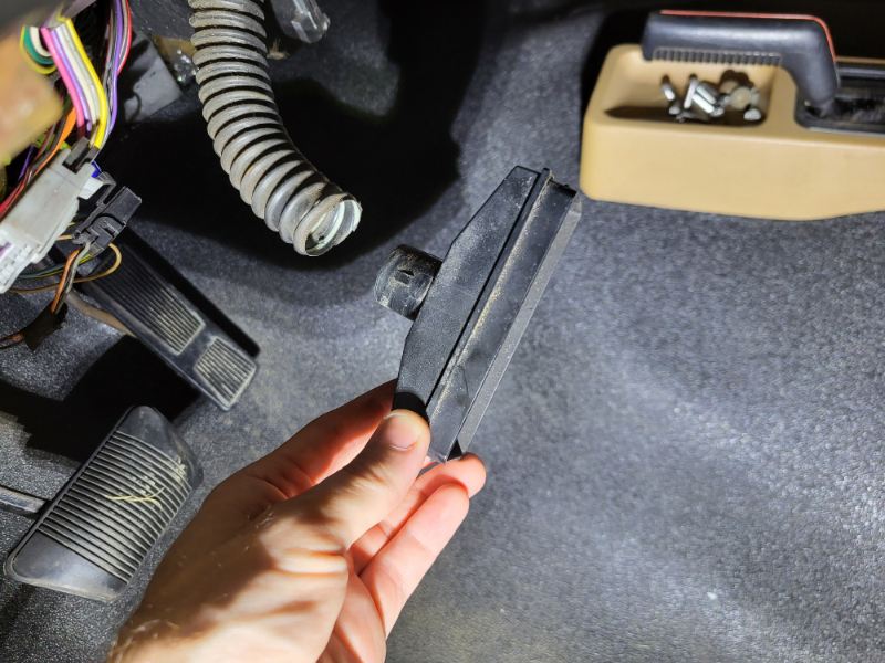
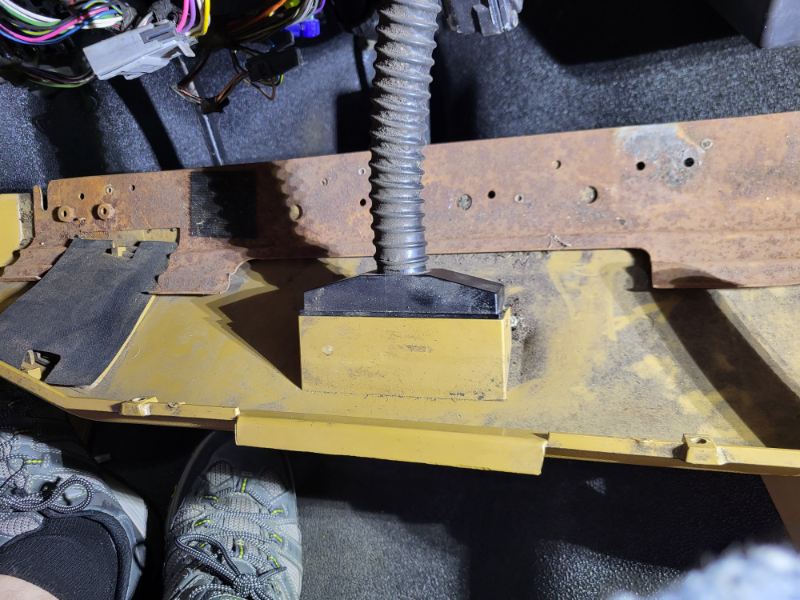
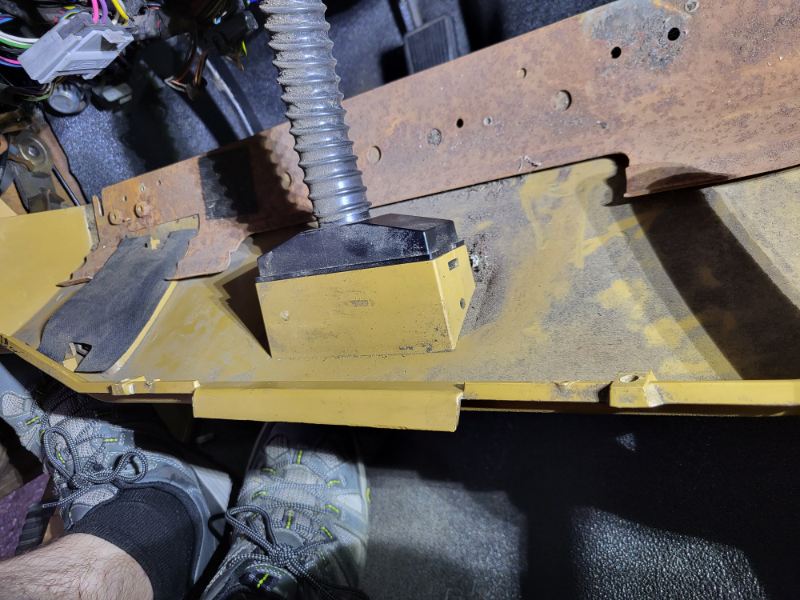
That was one of the most foolish part mates I've seen. It's not even threaded, just a tab that fits into a slot of the corrugated plastic tube. Boy I wished I had known about this like an hour and a half ago. Thanks for the input @Eagle_SX4
-
I figured it out. I had to use a flat head screwdriver and a flat metal spudger. I ended up shoving the screwdriver into the plastic triangular tab and prying between the black plastic tube housing and the tan trim piece. I somehow did not break the plastic. There must have been far too tight a fit on that mate. I am going to trim the black plastic locking tabs with an x-acto so it does not take an exorbitant amount of force to remove the parts next time.
-
Has anyone determined how to remove the lower driver side dash cooler line below the steering wheel? I've been paying with plastic and metal tools and I cannot get it to separate from the lower dash. I've tried pushing in the tabs, piercing from the back side and prying, and even using flat head screw drivers to convince the parts to separate. Nothing seems to work. I really don't want to break it. Does anyone know how to properly remove this? Thanks!
-
$400 LWB in FL
Salvagedcircuit replied to H3ADBANG4L1F3's topic in Craigslist/eBay... i.e. Not Your Stuff
woah, are those original stripes? I've never seen that style. -
Looking good
-
1987 Comanche Pioneer Restomod
Salvagedcircuit replied to 996xj's topic in Member Projects: Your Comanches
The duct-tape crimps may only be a 87-90 AMC building technique. The crimps either went away with the engine harness c101 connector removal in 1990 or some chrysler engineers checked themselves into a local clinic after analyzing the cherokee / comanche assembly procedure. Good luck with it! -
1987 Comanche Pioneer Restomod
Salvagedcircuit replied to 996xj's topic in Member Projects: Your Comanches
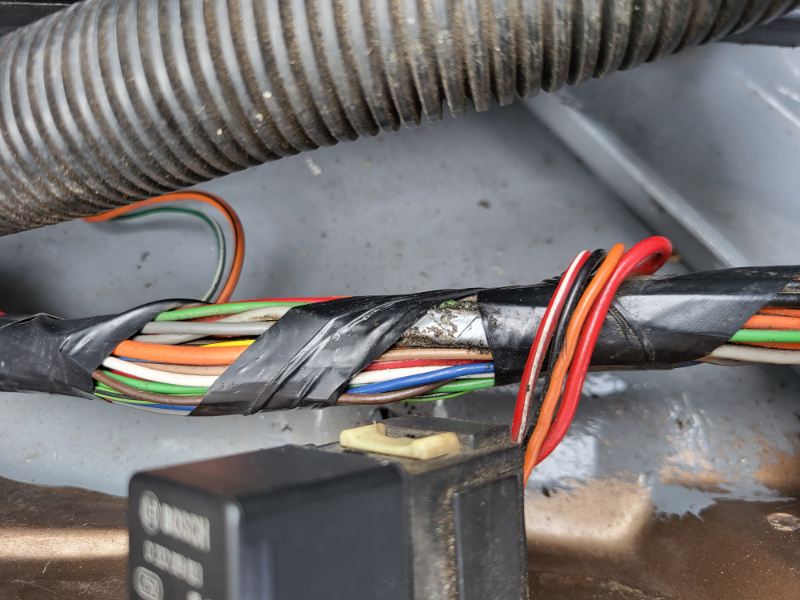
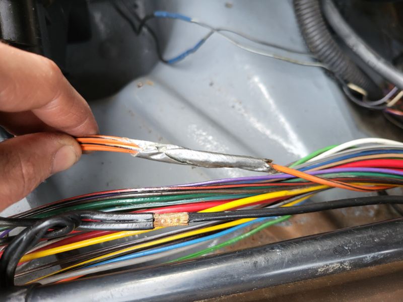
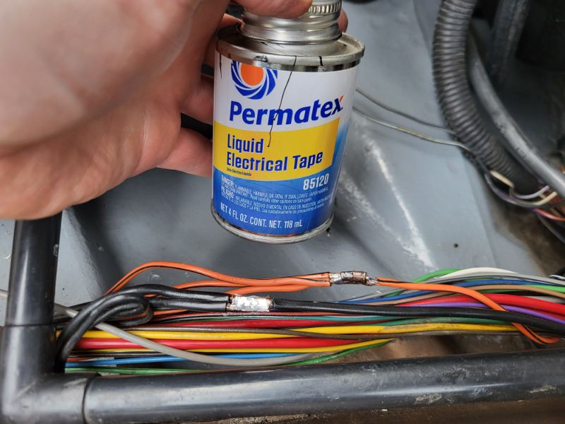
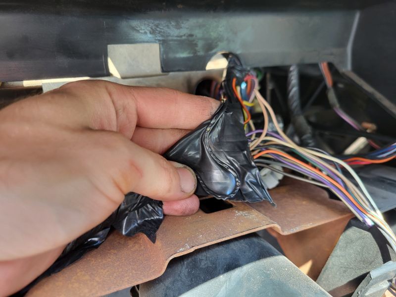
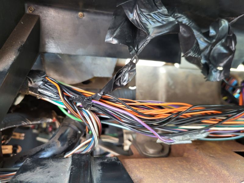
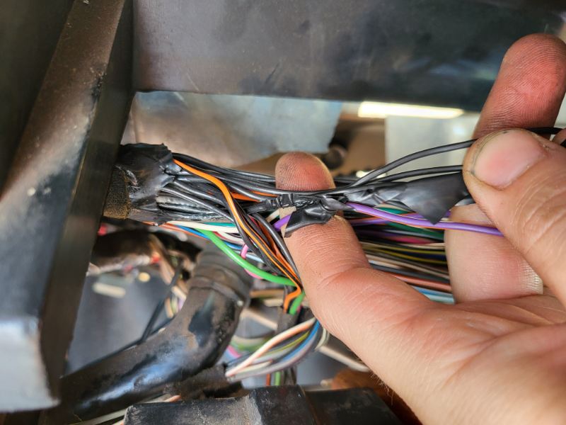
Very cool! You may find duct-tape crimps along your wiring harness journey. They look like the attached photos. They are indeed stock and vary in quality. Sometimes there is a brass ring that is compressed around other wires into a but-crimp. Other times its just 3 wires pinched together. The crimps are usually tight but sometimes there is a loose one. I de-taped mine and looked for any corrosion. If there was none, I just soldered over the crimp. I used paste flux and 63/37 solder. I then covered with liquid electrical tape. If there were signs of corrosion / cut strands, I just clipped off the region, added heatshrink and resoldered. Most of these wires are small enough gauge that a standard 70w hakko / weller soldering iron will do the business. Don't waste your time with the 35w and less irons, they are terrible.