
White_Comanche
-
Posts
263 -
Joined
-
Last visited
Content Type
Profiles
Forums
Gallery
Everything posted by White_Comanche
-
Nice looking Comanche on Marketplace
White_Comanche replied to Bill's topic in Craigslist/eBay... i.e. Not Your Stuff
Yes, it's a nice looking truck. However, I see its been sprayed all over with that cherry red. The over-spray can be seen on the door pin and the firewall. Plus, I gotta chuckle from the gloss that was sprayed thick in the engine bay Also looks to be on the tires too! I'd like to have a clean truck, but I very much dig the weathered and well-used look of many Comanches all around this site. -
I'm the same boat you're in. I bought my 86 Comanche late last year and I didn't know jack. The guys on here are extremely helpful and I've been learning a lot. I find working on my MJ incredibly enjoyable. You might be pulling your hair out from time to time, but you're also learning too. Overall it looks like a nice clean truck. Like the red/black interior. Seeing a few exterior shots showing the whole vehicle will be cool...
-
Sweet moonroof bad Comanche too
-
ideas for taillight removal
White_Comanche replied to Pete M's topic in MJ Tech: Modification and Repairs
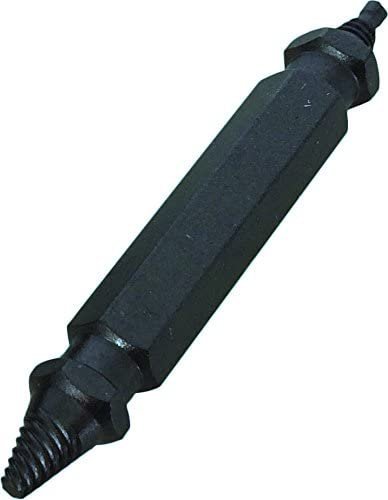
I see that you successfully got the screws out. Just wanted to add a method that might not be commonly known. Century Drill makes damaged screw removers and extractors.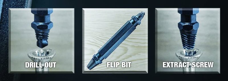
-
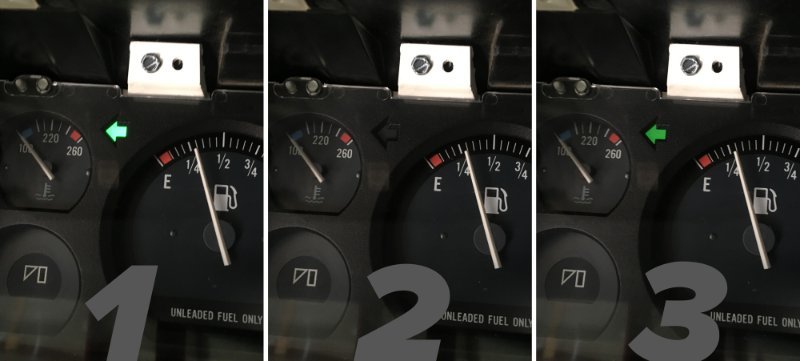
A few weekends ago I successfully reinstalled my instrument cluster. Much time was spent cleaning up the cluster as a whole. All new light bulbs were installed. I did repeated continuity tests on all electrical paths on the laminated circuit board until I was satisfied everything worked. Note: for anyone who has not removed/installed their instrument cluster I discovered the unit can slide back in much easier by removing its clear plastic 'lens'. It creates an extra 2 or 3mm of needed clearance. Also, removing the digital clock and cigarette lighter makes re-connecting the speedometer cable a breeze. During all of this I made sure both of the electrical connectors were properly seated into the cluster housing. I wanted to ensure all four clips were actually fully clipped in. When removing the cluster I may have noticed my C203 connector was not positively seated down in the first place. I'm happy to report that my left turn signal indicator light now WORKS! I'm cautiously leaning towards this issue is now fixed. If this reoccurs in the future I think there's only one other thing it could be. Big thanks to everyone who has helped me work through this.
-
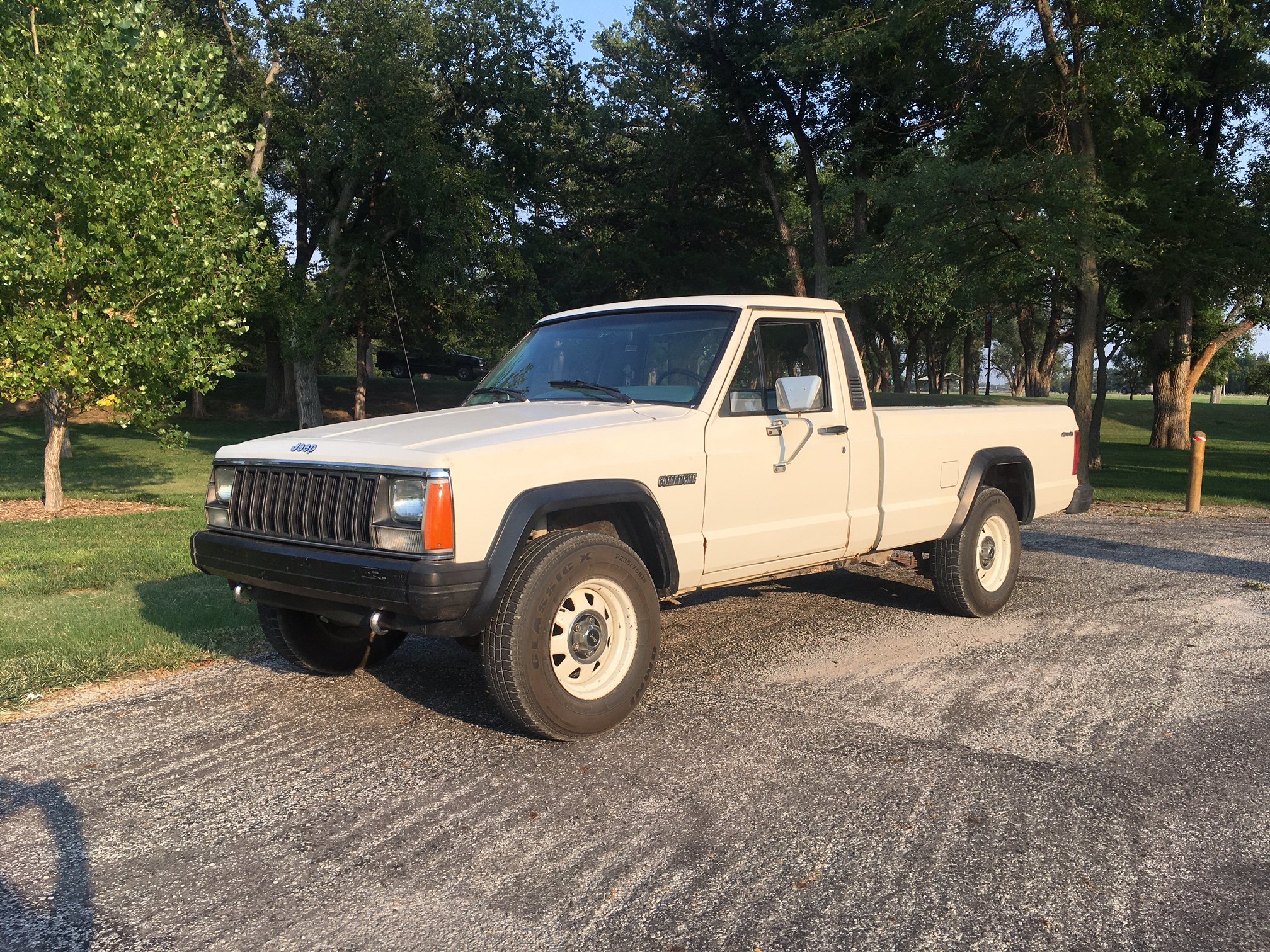
Nice tires! Have not seen a Comanche at factory height with such large ones. At first thought the black wheels we're playing tricks on my eyes... pretty rad
-
Thank you for the interest, will do. I did however complete a side project on my Jeep this weekend, Imagine that I'll put the dash back together next weekend.
-
I think you, and the others have given me great help to figure this issue out. Greatly appreciate you taking the time to consider it all, and explaining the testing procedure in a way that I could get it done. Highly doubt I would have got as far as I did without it. I'm gonna go ahead and assemble everything back together soon. Earlier in this thread I briefly mentioned that my C203 didn't seem positively seated when I was taking the cluster out in the first place. I remember the top-most squeeze clip seemed almost unclipped when shining a flashlight on it. If my suspensions are correct, after I get everything back together, proper pressure will always now be applied to the C203_10 & C203_11 (which are at the top of the connector)... and against the laminated circuit board.
-
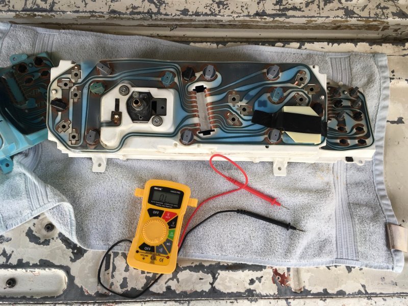
Ωhm, Following up with the testing to diagnose my intermittent left turn signal bulb. I purchased a manual multimeter for testing — Performance Tool #W2974. Not a professional model, but it was affordable. TEST 1 C156_H ├———————————————┤C203_11 Disconnect C156. Disconnect C203. Check for continuity between these two points (GRY/BLK) on the IP Harness side. • Result: Continuity was strong, with a loud beep, 0.0 showed on multimeter. TEST 2 Connect C156. With C203 disconnected measure for voltage between C203_10(BLK) and C203_11(GRY/BLK) with KEY ON and Left Turn Signal ON. Looking for 12vdc_0vdc_12vdc_ect_ect. Try and select a 20vdc range on your DVOM. In other words, auto ranging OFF. • Result: Voltage maxed out on the display at 8.99V. A friend suggested that I use a circuit tester for a visual aid in case my cheap multimeter wasn't quick enough at detection. I'd say the circuit tester illuminated at max brightness. Afterwards I did a control test on the battery (it had equal brightness). As an aside, the day before I took apart my instrument cluster to give it a good dusting and cleaning. Replaced every bulb as well. Continuity is present across all electrical paths. I'd like to know your thoughts. Thanks for the help.
-
Thanks for spelling out how to properly do these tests. Appreciate you getting quite specific. Electrical testing is quite foreign to me. I might go ahead and get a more capable multimeter. That yellow one you see in the photo is quite basic—only has auto ranging. *************************************** Disconnect C156. Disconnect C203. Check for continuity between these two points (GRY/BLK) on the IP Harness side. I don't understand this testing. It was quite late when writing the update that you quoted. Just realized that I had a typo with identifying that connector. Thanks to you, I now know specifically what continuity test to do. I'll report back.
-
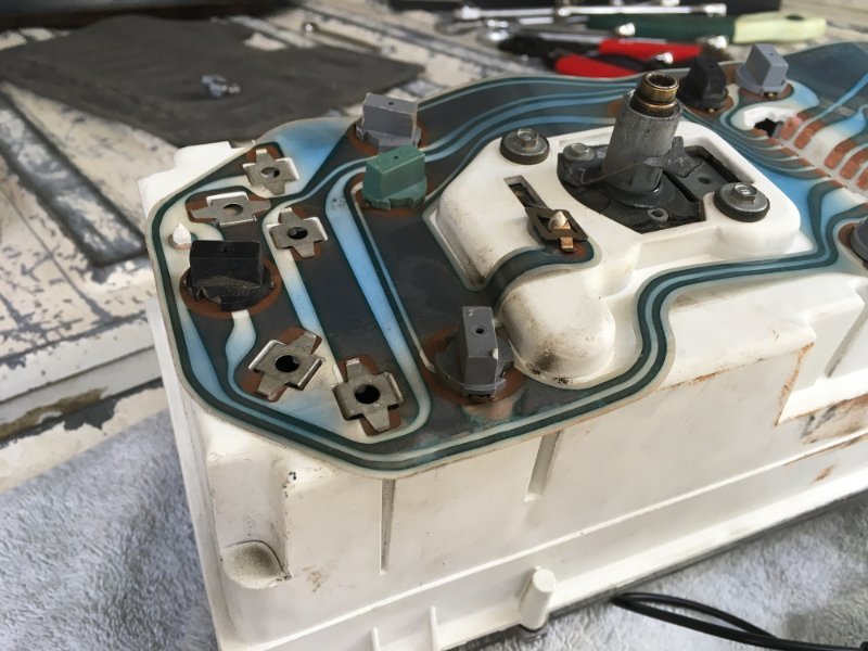
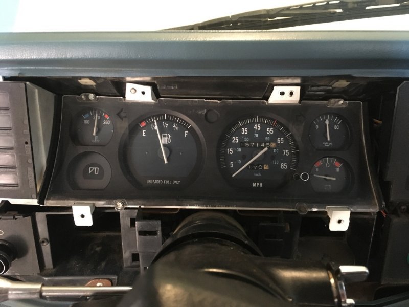
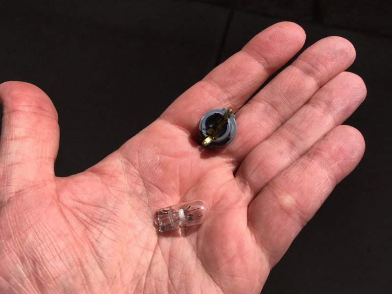
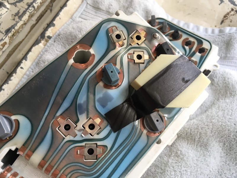
I was finally able to remove my instrument cluster this weekend. To recap, the reason for doing this is to get my Left Turn Signal Bulb (in the cluster) to work properly. Sometimes the bulb illuminates... but most of the time it does not. Work done prior to this consisted of refreshing the cabin instrument ground, cleaning up the front drivers side C102 electrical connector, and finally checked out if that C156 turn signal connector had any loose wire crimps (there were not). Everything went well taking the cluster out. Unbolting the speedometer cable clip from the suspension arm created enough slack for removal. Below are pictures detailing everything. 157,145 MILES C203 CONNECTOR C204 CONNECTOR EMPTY LEFT TURN SIGNAL SOCKET LEFT TURN SIGNAL BULB & SOCKET LOOKS 'OK' PARTIAL DE-LAMINATION DETAIL CONTINUITY TESTING For some background, I know the previous owner removed the instrument cluster. It was to replace the speedometer cable. If I'm not mistaken, my central C203 connector seemed a tad-too-easy to remove. It may not have been positively clipped in. Dielectric grease was present. I did many continuity tests to check the "bridge" between each light socket. Checked most, if not all of them. Everything beeped. 1 or 2 sockets needed to be removed to re-seat the bulb. After this, all electric connections now flow. I'm really unsure of what to do besides what I already have bullet pointed. Have next to zero experience with this stuff, but hey, I already have a few successful Comanche projects under the belt. Next to do... • Install all brand new bulbs • Burnish all the brass socket contacts • Do a continuity test between the turn signal connector (under dash) and the middle C102 connector Is there anything else you guys think I should do before closing this thing up? ...other than some polishing, dusting and lubing. Thanks a lot guys. This site is invaluable.
-
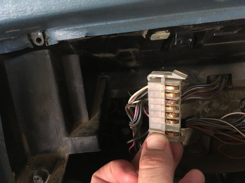
I did a preliminary inspection of this turn signal connection. Yes, there is indeed two (2) wires in 'H'. They seem to be seated and crimped securely. No signs of distress. This C156 on my '86 happens to be black in color, but I knew I located it by the shape of the plug. This points me directly to removing the instrument cluster now. Guessing either that left blinker socket or bulb went south. If you guys have done this before, please let me know if there's anything to be mindful of when removing the cluster assembly. Might not get to this project for a few weekends... but it'll be good to know of anything prior.
-
Keep in mind that I'm learning with my Comanche on how to "work on vehicles". I'm very much green. Please tell me more specifically what this means. Does this have to do with the fuse panel, or somewhere else?
-
I think you may not have read my introduction to this topic, or I got lazy at writing the latest update. Basically, after all this effort my issue still remains... which is my LEFT Turn Signal Indicator bulb in the cluster doesn't illuminate most of the time. Sometimes it does work however. All other lights work inside the cluster — except there's a few tiny bulbs left of the steering wheel that don't light up anymore — such as the green "4WD" light. I presume these are burnt out. There's another, but I can't remember which. All my exterior lights work as they should. In other words... when pressing down on the stalk (making a left turn) the left cluster blinker is usually dark, but other drivers can always see that I am indeed about to make a left turn (because all exterior lights work). Does this change what you think the problem might be?
-
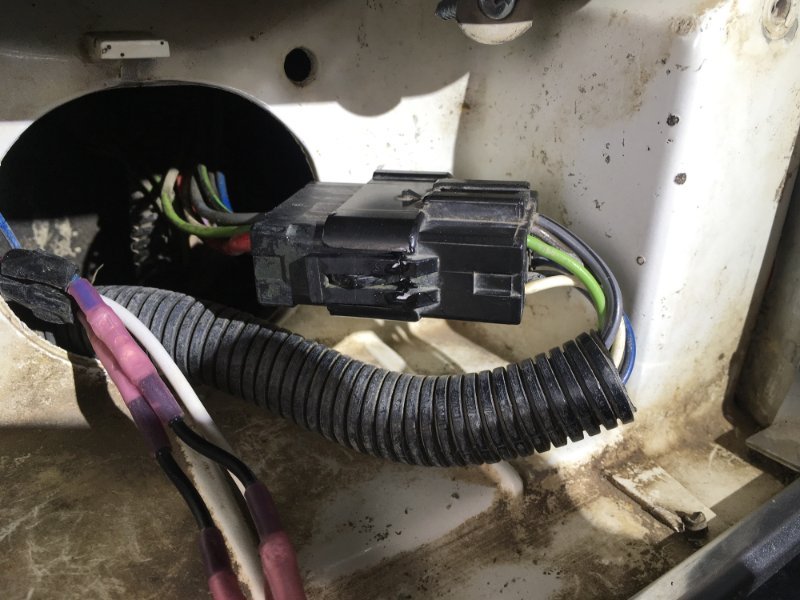
In the morning with a fresh eye and mind I realized that I could epoxy this broken clip after the connector was mated together. Yes, this connector does snug. With this clip reattached it prevents the assembly vibrating apart. For added strength I wrapped a loop of electrical tape around just for the clips. I did have zip ties in mind, but after this light bulb moment it seemed unnecessary. ATTACHED BROKEN CLIP WITH EPOXY *AFTER* MATING CONNECTOR ELECTRICAL TAPE REINFORCEMENT AFTER EPOXY CURED Unfortunately... this weekend of work did not get my left turn signal to light up. Thankfully, all the exterior and interior lights still function normally like nothing happened. So I guess, with the instrument cluster ground refreshed, and this connector properly cleaned of corrosion, the only thing left to do is remove the gauge cluster and see if that left turn signal bulb and socket needs replaced. Am I going down the logical path here? Thanks guys for all the input while I get this issue figured out.
-
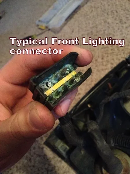
Just seen on Cruiser54's famous relay/receptacle refreshing webpage with the exact same broken clip. Must be fairly easy to break. It's very similar to Bakelite plastic. I'll see how snug this thing mates together tomorrow. If it doesn't feel right I'll do more research on 10-pin weatherproof connectors. Thanks guys.
-
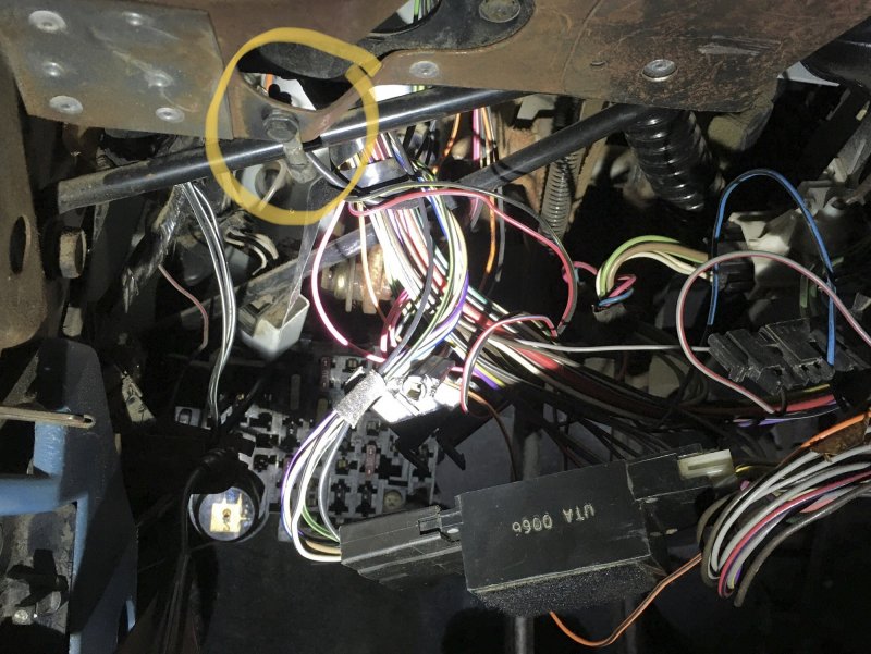
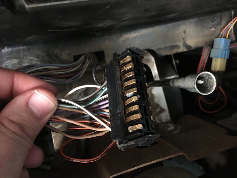
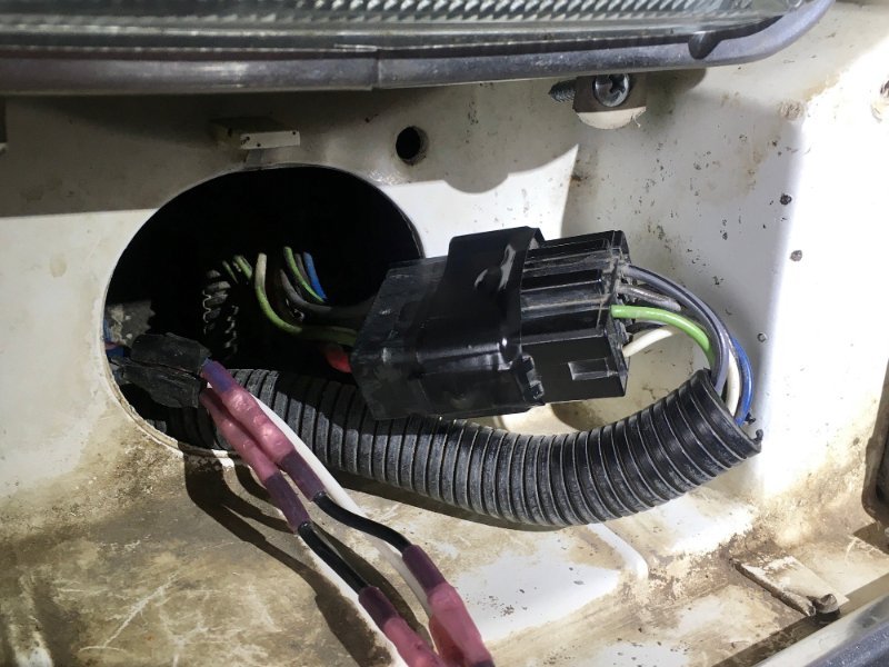
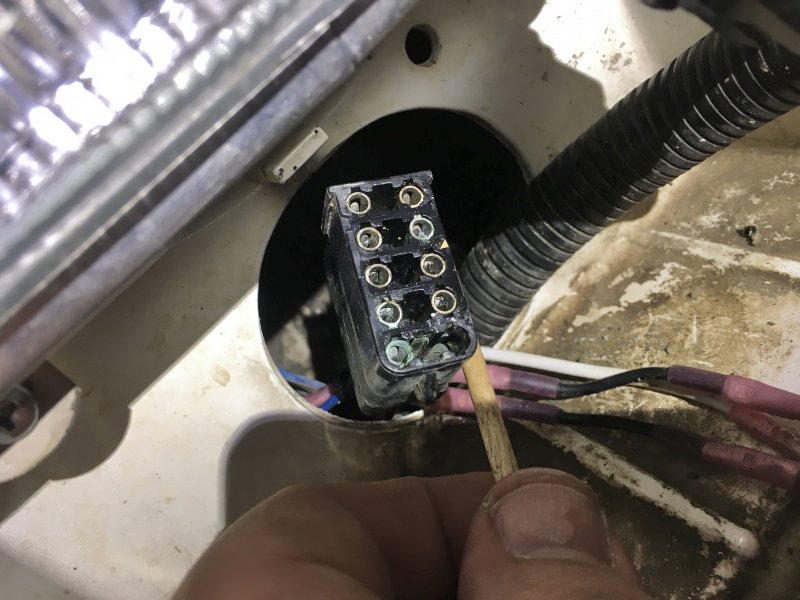
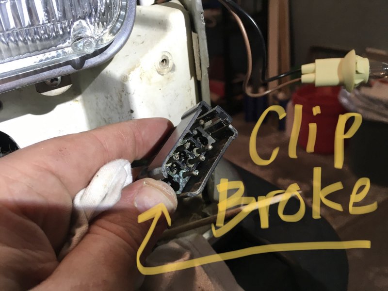
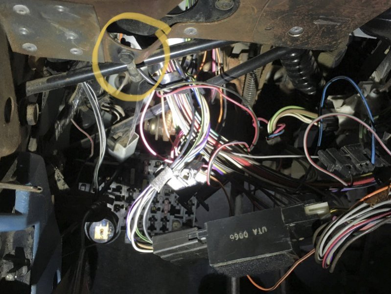
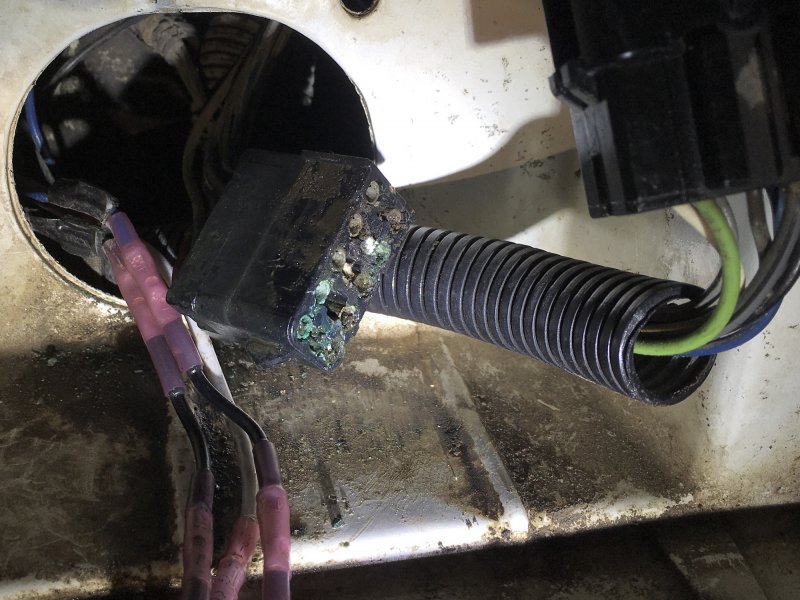
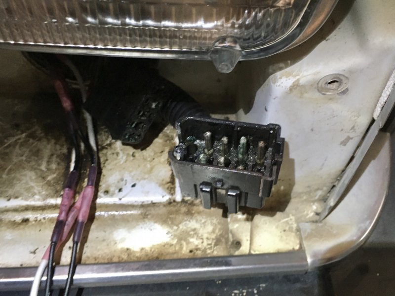
Tackled part of this project today. Everything went fairly well considering it all. Refreshing the instrument cluster ground was a snap. However, disconnecting the electrical connection behind the driver's headlight was very tedious. The mating pair was very corroded and difficult to break apart after these 36 years. I ended up snapping off one of the side clips. Spraying loads of QD® electrical connection cleaner did a good job of flushing everything out. REFRESHED INSTRUMENT CLUSTER GROUND CORRODED FEMALE END CORRODED MALE END CLEANED FEMALE END You guys know if this male-end connector can still be purchased? Maybe Dorman or some other manufacturer... or am I SOL on this? I really don't know what this connection is specifically called either for research purposes. Thanks for reading and I appreciate any input.
-
Thanks Eaglescout for the note. I'll report back on the results when I do this project soon. I didn't know that plug behind the left headlight isn't weatherproof. That makes since why attention to the plug is so often mentioned for various electrical issues. I have reviewed Cruiser's Tips a few times. It's quite a good write up for people like me who don't have any real experience working on vehicles. I bought my Comanche in August of 2021 and am slowing working out the problem areas. It's awesome that a resource like Comanche Club is dedicated solely to these older trucks. Glad it's around.
-
Before writing this I scoured Comanche Club to see if any MJ owners have had this same issue. After much searching I've found some posts with similar problems, but not exact matches. In my instrument cluster, the LEFT Turn Signal Indicator sometimes works (and) sometimes it doesn't. It's quite finicky and annoying to not see blinking. Probably 40% of the time it illuminates, while 60% it remains dark. - Replaced both front end Turn Signal sockets & bulbs - Replaced both front end Side Marker sockets & bulbs - Replaced every bulb in the Tail Lights - Turn signal Flasher is NEW - All exterior lights function properly - All fuses are NEW and none are blown - TURN B/U fuse terminals feel nice and tight - Cleaned the fuse block with QD® Electronic Cleaner & Canned Air Nearly every Tail Light socket had serious corrosion (the old front Turn Signals did as well). Had to use precision pliers, PB Blaster and a heat gun to work out each of the broken bulbs. Was a real mess. All exterior bulbs now have dialectic grease. Below is what I thought of doing to get the indicator working properly: • Clean up instrument panel ground below the dash • Remove instrument cluster to clean and/or replace blinker light sockets & bulbs • Separate and clean out that wire connector behind the driver's headlight Am I on the right track to resolve this issue? Or would you guys recommend trying something else?