
fiatslug87
-
Posts
7281 -
Joined
-
Last visited
-
Days Won
8
Content Type
Profiles
Forums
Gallery
Everything posted by fiatslug87
-
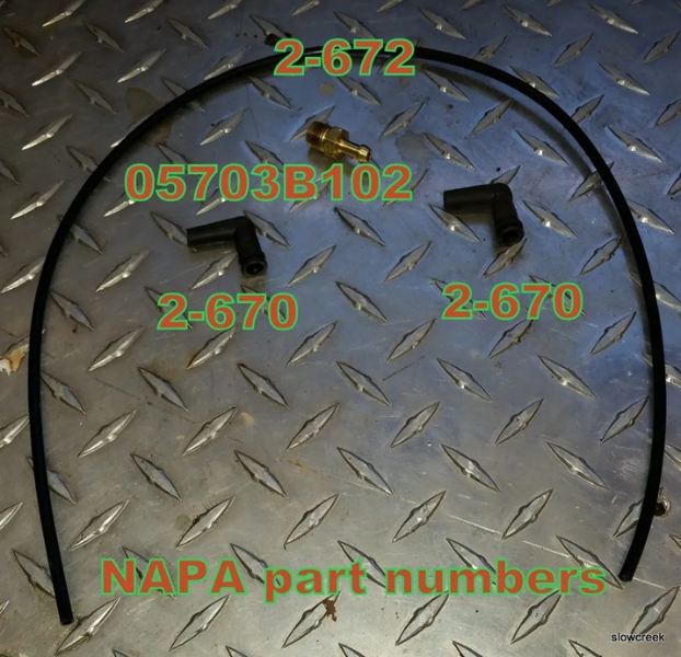
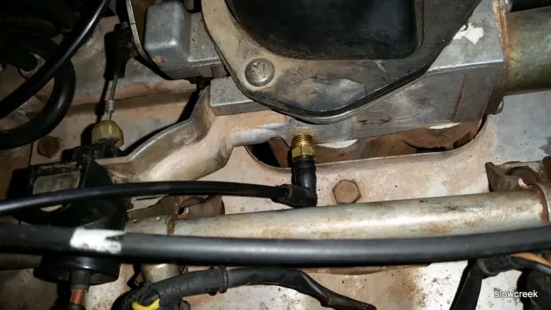
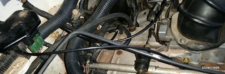
CRUISER'S MOSTLY RENIX TIPS THROTTLE BODY TO MAP SENSOR HOSE FIX The Renix throttle bodies have a strange and failure prone connector on the side where the MAP supply originates and then runs up to the MAP sensor located on the firewall. This hose/pipe assembly is no longer available for purchase. The real kicker here is how critical this line is in supplying the correct vacuum signal to the MAP, the most relied upon sensor for the ECU to read regarding air/fuel ratio. Any cracks, melted spots, or loose rubber connectors can cause major starting and driveability issues. There’s a simple fix though. All that’s required is a 1/8” NPT tap, a new throttle body gasket ( Napa FPG 60742 ), a vacuum fitting (Napa 05703-B102), two vacuum elbows (Napa CRB2670), and a length of new plastic piping (Napa CRB2672). Remove the throttle body and take it to the workbench. Using an oiled tap along with a driver, carefully thread the lower of the 2 holes of the throttle body where the old fitting was plugged in. Don’t go too deep. These are pipe threads. Flush the hole with carb cleaner and inspect for any left over cuttings. This is an excellent time to do a complete throttle body and IAC cleaning. See Tip 11. Take the vacuum fitting (05703-B102 ) and apply a LITTLE bit of thread sealer on the threads only. I prefer Permatex #2 but almost anything is fine. Carefully screw the fitting in until snug. Install one of the vacuum elbows on the MAP sensor so it points toward the throttle body, and the other vacuum elbow on your new throttle body fitting so it points up to the MAP sensor. Cut a length of the new plastic tubing (approximately 13 inches) to fit between the vacuum elbows and install it making sure there is enough slack for some engine movement. Route it according to the photo. We don’t want any rubbing or chafing with engine movement. Not a bad idea to use some contact cement or Gasga-Cinch sparingly on the tubing to elbow connectors. Revised 2-06-2016
-
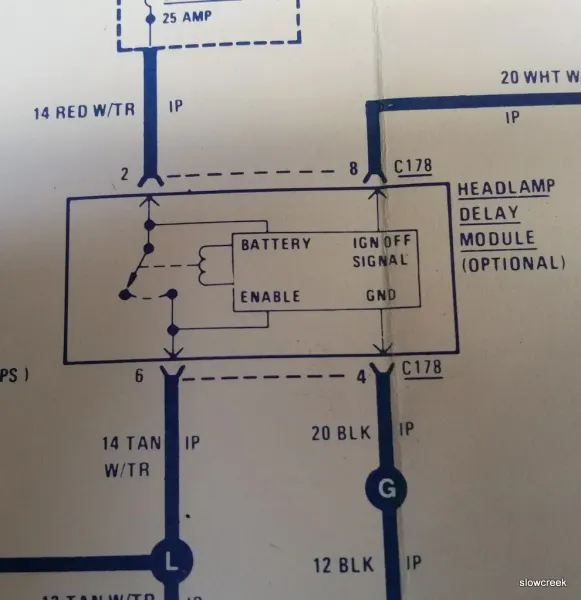
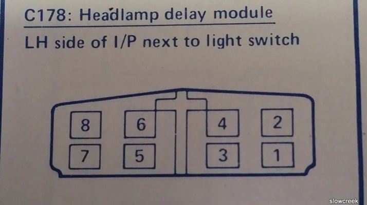
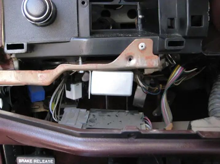
 CRUISER'S MOSTLY RENIX TIPS ADDING THE SENTINEL HEADLAMP FEATURE I love the Sentinel Headlamp feature. It allows my Jeep to provide me with safe lighting after exiting it at night. We live in a rural area with no street lights. Here how it works. I researched an old wiring diagram and found that all that was needed to have this feature was plugging in a relay!! And, the plug is already in our Jeeps. The relay is part number 56000636 or 56009324 and sells for about $50. Since I part out XJs and MJs, I went through my stash and found I had saved a few without knowing what they were. Think “junkyard” here. I simply plugged the relay/timer in and instantly had sentinel Headlamps. Revised 1-31-2016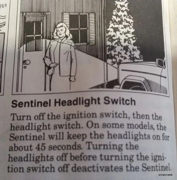

-
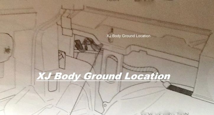
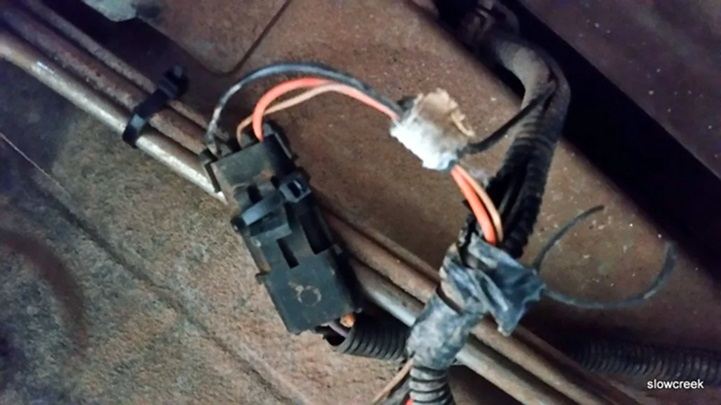
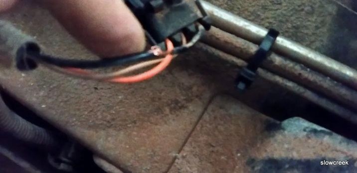
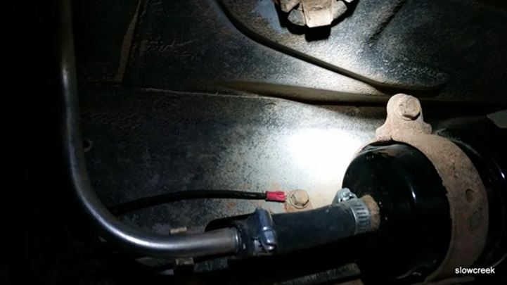
CRUISER'S MOSTLY RENIX TIPS IMPROVING THE FUEL PUMP GROUND The fuel pump and fuel tank sending unit ground at a sheet metal screw up behind the spare tire on an XJ, and behind the driver’s taillamp on an MJ. Not only is a sheet metal screw a lousy way to ground things, this ground path is long and travels through some connectors that are prone to corrosion and moisture. Locate the black wire on the HARNESS side of the fuel pump/sender 3 wire connector. Remove a 6″ length of the split loom covering. Strip back about 1/2″ of insulation from the BLACK wire. Take your new ground wire, preferably at least 14 gauge and 12 to 18 inches long as needed, strip it about 3/4″, and wrap it around the exposed part of the harness plug wire. Solder the connection. Tape it up and reinstall the split loom covering. At the other end of your new ground wire, add a crimp on eyelet. Attach the eyelet under a bolt that goes directly into the chassis. Be sure to clean the attaching point til shiny and apply OxGard to the contact surfaces. Revised 10-16-2018

-
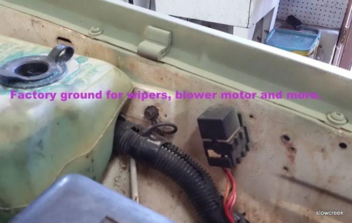
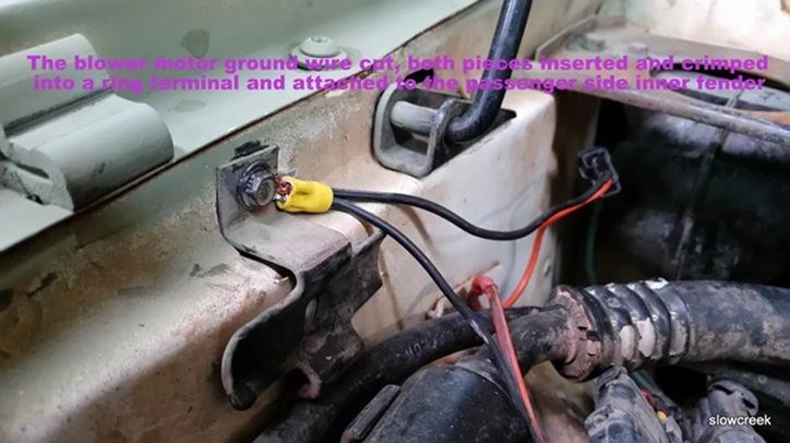
CRUISER'S MOSTLY RENIX TIPS IMPROVING BLOWER MOTOR PERFORMANCE On 1984 to 1990 MJs and XJs, the blower motor’s factory grounding point is on the driver side inner fender under the sheet metal screw. This ground is shared with windshield wipers, front windshield washers, rear windshield washers, AC clutch relay, fan control relay, fog lamps, fan motor, headlamps, front turn signals, front side markers, and park lamps. So your blower motor has its ground point 10 feet away from where it is located!! What we’re going to do is leave that ground intact and also ground the blower motor on the passenger side inner fender much closer to the blower motor itself. This will also benefit the other components on the factory ground circuit. Take this opportunity to refresh the factory ground as a matter of course. Remove the screw, scrape the surface to bare metal and reinstall the screw securely. Here’s what I do to get the ground much closer to the blower motor and add another ground point to this overloaded ground circuit. Find the blower motor connector on the passenger side. Red and Black two wire connector. Find a location where the black wire can be made to reach the passenger side inner fender, and cut the wire. You may have to do some rerouting of the harness to achieve this. Take both cut pieces of wire and put them together into a yellow eyelet and crimp. Fasten the eyelet to a place on the passenger side inner fender with a sheet metal screw after applying OxGard to the contact surfaces. Be sure to scrape the attaching point on the fender to bare metal first. Your blower motor will now turn faster and last longer, and the other electrical components on the circuit will benefit from a better ground path. Revised 01-31-2016
-
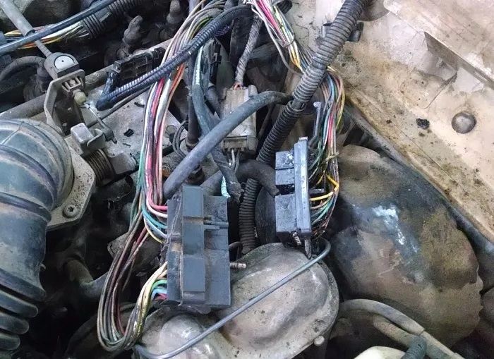
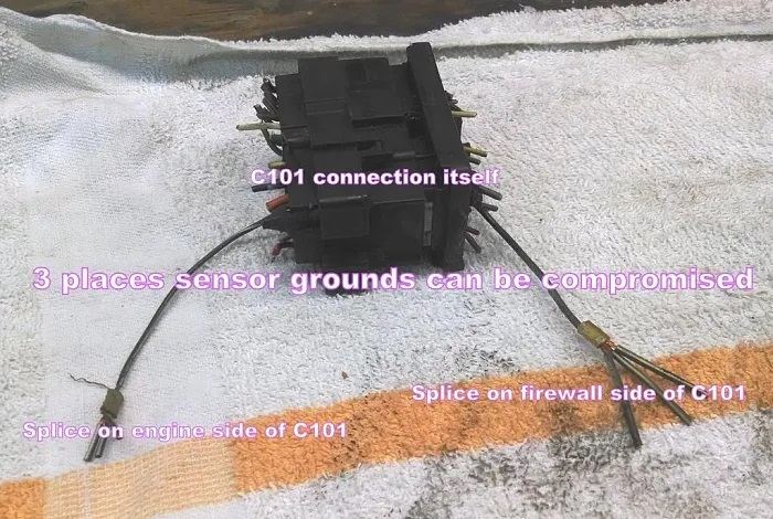
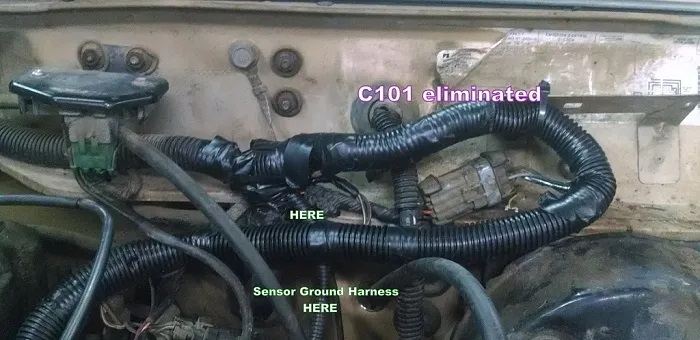
CRUISER'S MOSTLY RENIX TIPS C101 ELIMINATION As noted in Tip #2, Renix C101 Connector Refreshing, in 1989 the factory wiring harness no longer included the problematic connector. For a long-term fix that will avoid many problems in the future, it is a good idea to just get rid of the thing entirely. Unbolt the 2 halves of the C101 using a ¼” socket. On each half there is a plastic cover where the wires enter. They are removable but you’ll probably end up busting them off. Lightly bolt the C101 back together, away from the firewall. Peel back the split-loom covering from the body side of the C101 connector down to where the harness splits and goes toward the firewall, pretty much below the MAP sensor. On the engine side, remove the split loom about the same distance. Now you can see from one side of the C101 to the other. Beginning at the top row, closest to the motor, be absolutely sure you cut the matching wires on each side of the connector off to about 1/2 inch. This will allow you to verify the original position of each wire color in case of mistakes or confusion. CUT AND SOLDER ONE PAIR AT A TIME. The wires may be wound a bit in their looms. See the first photo. Get them unwound neatly and do the following, ONE AT A TIME. Slide your shrink tube over one wire. In a well ventilated area, solder the wires together and then slide the shrink tubing over the solder joint. Heat the shrink tubing so it seals your completed solder joint. Keep going until you’ve done all 22 or so connections. Both sides of the C101 connection have a wire that is brown with white tracer. Follow each of these wires back until you come to a point where three wires are crimped together. What you want to do here is cut the crappy factory crimp out of each set of three and bring both sets of three wires together and solder them together, using shrink tubing as well. All 6 wires. These particular wires will not end up in your normal C101 elimination loom. The sensor ground upgrade is found in Tip 6. After all the soldering and shrink tubing is done, bundle the wires together in a new piece of 3/4″ split loom. Tape it up and secure it to the C101 connector’s original bolt hole or somewhere else along the firewall so it will be protected. Revised 01-31-2016
-
CRUISER'S MOSTLY RENIX TIPS OIL FILLER CAP MOD We all get tired of the oil film/leak on top of our 4.0 Jeep aluminum valve covers. Many times the biggest culprit is the loose fitting oil filler cap. Here’s a real easy fix: Remove the plastic oil filler cap and wrestle the original rubber gasket from it using a small pick or screwdriver. Make a duplicate of the gasket out of an old bicycle inner tube using scissors and a knife or razor blade. Install the duplicate on the cap first, and then the original over top of it. It will be a tight fit on the valve cover the first time, and may require some persuasion with a pair of pliers, but will get easier with time. Revised 1-31-2016
-
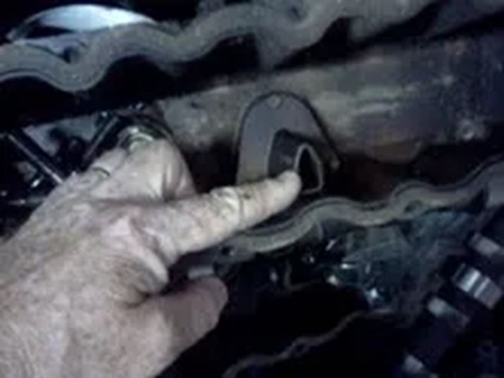
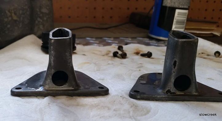
CRUISER'S MOSTLY RENIX TIPS CRUISER’S VALVE COVER MOD Most early and even later Renix 4.0s could be bothered by excessive oil in the air cleaner box. A fix from my old days as Service Manager at a Jeep dealership follows. Information was provided to me from a buddy at JeepTech during those days. I don’t believe it ever came out in a Technical Service Bulletin. Remove the valve cover and turn it over. Next, remove the fluted tubes that are now facing you by removing three screws on each. Chop 1 inch off each of them. Then, drill a half inch hole as shown in the photo. The flat side of the flute that’s closest to the edge of the valve cover. Clean and de-burr/sand all rough edges nicely, clean with solvent, and reinstall. Don’t be concerned about the chintzy gaskets that will probably crumble into oblivion when you remove the fluted tubes. They can go back together without gaskets. Revised 09-12-16
-
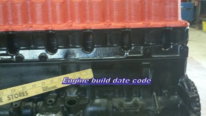
CRUISER'S MOSTLY RENIX TIPS 4.0L ENGINE DATE CODES The date code is on the passenger side of the engine, on the block, just forward and up from the distributor on a machined flat surface. The digits of the code identify: 1st Digit-The year (8 = 1998). 2nd & 3rd Digits-The month (01 – 12). 4th & 5th Digits-The engine type/fuel system/compression ratio (MX = A 4.0 Liter (242 CID) 8.7:1 compression ratio engine with a multi-point fuel injection system). 6th & 7th Digits-The day of engine build (01 – 31). FOR EXAMPLE: Code * 801MX12 * identifies a 4.0 Liter (242 CID) engine with a multi-point fuel injection system and 8.7:1 compression ratio that was built on January 12, 1998. Revised 1-31-2016
-
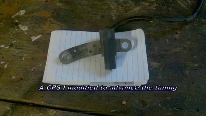
CRUISER'S MOSTLY RENIX TIPS RENIX CPS ADVANCE MOD The sensor portion of the CPS needs to slide up the perforated bar towards the top of the engine. Mark the perforated bar’s top end with paint or marker. Place the CPS in a vice, just not quite clamping the bar, the sensor resting on the vice jaws, with the Top part protruding. Place a bolt that fits tightly into the hole at the Top part of the bar. With a hammer, tap the Top part of the bar and it will slide through the sensor portion of the CPS. Stop when the sensor portion is about 3/8″ from the edge of the bolt hole. Revised 1-31-2016
-
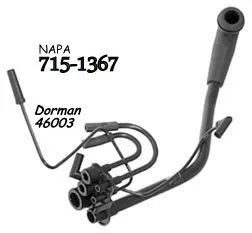
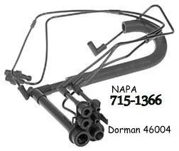
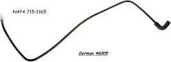
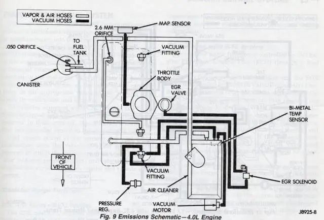
CRUISER'S MOSTLY RENIX TIPS RENIX VACUUM HARNESSES The vacuum harness that attaches to the front of the valve cover and includes the grommet/fitting, and is called the front harness, is Napa part number BK 715-1367 or is a Dorman 46003. The vacuum harness that is closest to the air cleaner, EGR etc, and is called the rear harness, is Napa part number BK 715-1366 or is a Dorman 46004. The tube from the rear of the valve cover to the intake manifold is part number BK 715-1365 or Dorman 46005 and comes with the valve cover grommet. The Throttle Body to MAP hose is no longer available. Click HERE to access a fix for that. Revised 2-6-2016
-
CRUISER'S MOSTLY RENIX TIPS EGR VALVE TEST Valve Opening Test With engine at normal operating temperature and at idle, rapidly open and close throttle. Open throttle sufficiently to obtain at least 1500 RPM. Movement should be noticed in EGR diaphragm. If diaphragm does not move, probable causes are: faulty vacuum signal to EGR, defective EGR diaphragm or defective backpressure sensor diaphragm (if equipped), or leaks in vacuum lines or connections. Valve Closing Test With engine at normal operating temperature and at idle, manually depress EGR valve diaphragm. RPM should immediately drop, indicating that EGR valve is not leaking and had been properly cutting off exhaust gas flow at idle. If there is no change in RPM and engine is idling properly, exhaust gases are not reaching combustion chamber. Check for plugged passage between EGR valve and intake manifold. If engine idles poorly and RPM is not greatly affected by manually moving diaphragm up, EGR valve is not closing off exhaust gas flow. Check for carbon between pintle, leaking EGR valve gasket or bad EGR valve. Revised 1-31-2016
-
CRUISER'S MOSTLY RENIX TIPS SHIFTING THE TRANSFER CASE Here’s how the factory suggests you shift the transfer case and I’ve been doing this since these things were new and I worked at the dealership. Quoted from the owner’s manual. The suggestions in BOLD are mine. “To engage, shift the transfer case lever from 2H to 4H while the vehicle is moving at any legal speed”. I let off the gas, throw the lever, tap the gas, and let off again. 4L position: ” To engage, slow the vehicle to 2-3 MPH , shift the transmission to Neutral, then shift the transfer lever to the right and pull firmly rearward to 4L”. To shift out of 4L, stop the vehicle, shift the transmission to Neutral, shift the transfer case lever to 4H, then the transmission to Drive (if you have an automatic), or First gear (if you have a manual), and continue on. Revised 1-31-2016
-
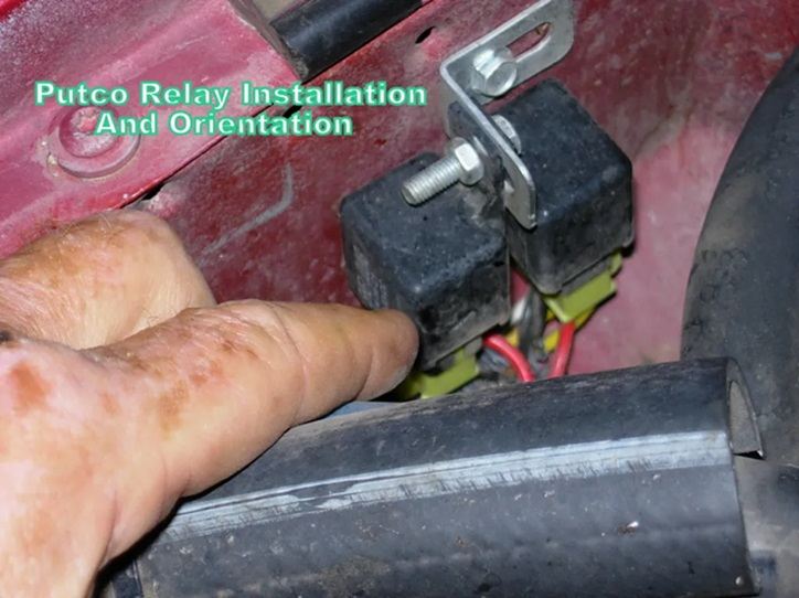
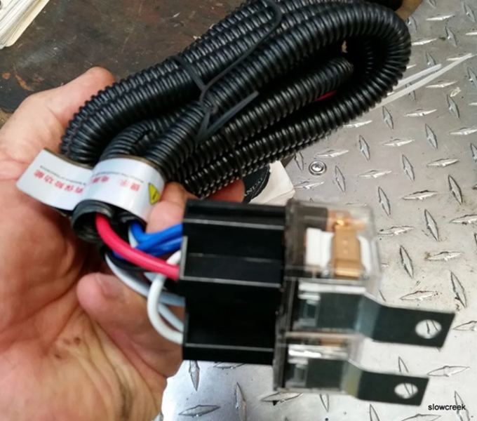
CRUISER'S MOSTLY RENIX TIPS HEADLIGHT HARNESS UPGRADE It’s easy to install a supplemental headlight harness. From the factory, the voltage to the headlight bulbs travels from the battery, through connectors, inside the cabin, to the headlamp switch, and then back out to the lamps via undersized wire and more connectors. It’s not uncommon to find only 10.5 volts at the lamps. The supplemental harness is installed so that it provides battery voltage to the lamps and is just triggered by the factory wiring. The result is about 35% brighter headlamps and headlight switches that don’t melt and burn out. Ebay has the harnesses. 2 headlamp H4 with ceramic connectors is what you want. You’ll likely be warned that the harness won’t fit your Jeep. It will absolutely plug and play: Remove grille and headlamp bulbs. I fed my harnesses from the passenger side starting between the battery and the back of the headlamp housing, over to the driver side. Plug the driver side bulb into the new harness. Attach the new harness’s ground wire under one of the small bolts on the radiator support after scraping the paint off under it. Attach the harness to the existing harness behind the grille working toward the passenger side. Plug the new harness plug into passenger headlamp. Plug original headlamp plug into receptacle on new harness. Attach the ground for the passenger side just like you did the driver side under a radiator support bolt. Attach relays with provided bracket on the passenger side inner fender. Connect power wires to battery. Revised 1-31-2016
-
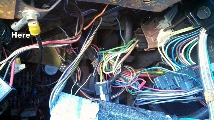
CRUISER'S MOSTLY RENIX TIPS IMPROVING THE INSTRUMENT PANEL GROUND The ground point for the complete instrument cluster on your XJ or MJ is located up under the driver’s side dash. If you lay on your back and look up under there with a flashlight, without wearing a hat, you will see a black wire attached to a shiny piece of metal almost directly above the hood release knob. The screw will have either a ¼” or 5/16″ head on it. This ground point is responsible for handling the ground circuit for the following items: Dome lamps, seat belt and key warnings, transmission power/comfort switch, wiper switch, headlamp switch and delay module, fog lamp switch, cargo lamp switch, all instrument panel grounds and illumination, power windows and door locks, cruise control dump valve, and a few more things. The problem is that where the ground point is located does not share good contact with the chassis where the ground should be. The solution is simple: Make up a jumper wire with #10 gauge wire about 10″ long. On one end, crimp on a ¼” round wire terminal. On the other end, crimp on a 3/8″ round wire terminal. Remove the screw from the existing ground wire and attach the small terminal of your jumper so that the original wire and your new jumper share the same attaching point, one over the other. Look above the driver’s side plastic kick panel just forward of the top of the hood release knob. You will see an 8mm stud there. Attach the large terminal end there with a washer and nut over it tightened securely. Use a coating of OxGard at all ground contact surfaces when attaching the screw and nut. **Special note for Comanche owners: Make your jumper wire 12″ long and attach it on the driver’s side kick panel close to the fusebox on the 8mm stud.**
-
CRUISER'S MOSTLY RENIX TIPS HO INTO RENIX SWAP This swap is easier than some will lead you to believe. And generally Pooh-poohed by those who have never done it. Those of us who have done it, like myself, will share with you the things that need to be done for a successful swap. Just think of it as swapping in a long block. XJ Cherokee and ZJ Grand Cherokee 4.0L engine blocks interchange. 2000+ TJ Wrangler and WJ Grand Cherokee 4.0L engine blocks interchange. YJ and 1997-1999 4.0L TJ blocks will interchange in XJ/ZJ XJ/ZJ blocks, and the 2000+ TJ/WJ blocks do not interchange without significant modifications. TJ/WJ 4.0L Engine blocks underwent clean sheet design changes effective in the 1999 WJ Grand and 2000 TJ Wrangler. These blocks are not interchangeable with XJ/ZJ engine blocks. The reason is motor mount bolt holes and belt driven accessory mounting bolt holes are in different locations, or not present at all, TJ/WJ vs. XJ/ZJ. Now that we know which engines we can use, let’s get down to business. The HO and Renix have some differences but none that can’t be overcome very easily. One running change was that the rear of the head was no longer drilled and tapped for the temperature gauge sender beginning in the 96 model year. The sender can be relocated to the threaded hole in the thermostat housing taken from an HO engine. You’ll have to extend the wire to that location. Some brave souls even drill and tap the HO head at the rear for the sender. You will be using the intake and exhaust manifolds from your Renix, along with all your sensors and wiring. Since the intake ports of the HO are slightly different, you use a new Renix gasket. Exhaust ports are identical. An alternative on exhaust manifolds: As far as exhaust, you can use the Renix exhaust manifold and be fine. If you want to use the HO exhaust manifold, you must go with an HO headpipe and screw your O2 sensor into that headpipe. Standard Renix harness is plenty long to do so. A bung can be welded into the HO manifold to accept the EGR tube. You will need to use your Renix distributor as it is different than the HO design. See Tips #12 – Setting Your 4.0 to #1 TDC and #13 – Distributor Indexing to be sure you get the distributor installed correctly. The flywheel or flexplate from the Renix must be used so your CPS gets the correct signals. The valve cover from the Renix allows you to keep your CCV system intact and requires no modifications. The HO block will have a plug in the coolant galley on the driver’s side of the block, closest to the front, which needs to be removed so your Coolant Temp Sensor can be installed in it’s place just as it is on the Renix. It requires a 5/16” square drive or a modified 3/8” drive that has been ground down to fit. Do this before installing the engine. As for the knock sensor, which is located just above the oil pan on the driver’s side of the engine about mid way, all the blocks I’ve seen are threaded for it. If not, I’ve heard they may be drilled but not tapped. Tap the hole if that’s the case. XJ: “Regular” (not Grand) Cherokees ’84-’01 ZJ: Grand Cherokee ’93-’98 (Gen1) WJ: Grand Cherokee ’99-’04 (Gen2) YJ: Wrangler ’87-’95 (Gen1) TJ: Wrangler ’97-’06 (Gen2) Revised 10-26-16
-
CRUISER'S MOSTLY RENIX TIPS VACUUM TEST FOR EXHAUST RESTRICTION Your vacuum gauge should come with an instruction booklet outlining the procedure. Hook the gauge up to a vacuum source on the intake manifold. Start the engine and note the vacuum reading. Usually 17 to 21 inches of vacuum. Throttle the engine up to 2,000 to 2,500 RPM for 20 seconds or so and the vacuum reading should stabilize to the same reading you got at idle. Let the throttle snap shut. The vacuum reading should shoot up about 5 inches of vacuum higher for a second and then come quickly down to the original reading. If the vacuum reading stays high and comes down slowly with jerky needle movements, you have an exhaust restriction. Revised 1-31-2016
-
CRUISER'S MOSTLY RENIX TIPS REAR MAIN SEAL DIAGNOSIS I’d be looking up ABOVE first, and VERIFYING the source of the oil leak YOURSELF. Everybody, who doesn’t own or have to pay for or perform your vehicle repairs, loves to poke their noggin UNDER the Jeep and come out bearing the false bad news that your RMS is leaking. Many mechanics, friends, and good old Uncle Bob seem to enjoy telling you it’s the rear main seal. Has a catastrophic ring to it, doesn’t it? A simple leak at the back of the valve cover or other source could produce the same symptoms. You don’t need to be a mechanic to figure this out. If you have good eyesight and a dim flashlight, you’re good to go on your own. Don’t jump on the RMS/oil pan gasket bandwagon right off the bat. Almost any oil leak on your 4.0 is gonna drip from the RMS area for two simple reasons: First off, the engine sits nose-up and any oil will run back to the RMS area. Secondly, the RMS area is also the lowest point on the engine. Simple physics and the old plumber’s adage apply here: “Crap flows downhill”. Valve cover gasket, oil pressure sending unit, oil filter adapter seals and distributor gasket, in that order, have to be eliminated as possibilities first. A little tip here. Rather than use a dizzy gasket, use an o ring instead. NAPA #727-2024. Tips 12 and 13 will help you get your distributor back in place correctly. Revised 10-10-2018
-
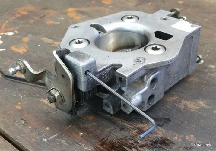
CRUISER'S MOSTLY RENIX TIPS RENIX THROTTLE BODY BUTTERFLY ADJUSTMENT Okay. Let’s start from scratch. First off, that’s not an idle adjustment screw. It’s a throttle butterfly stop screw. It’s purpose is to allow the butterfly to be as close to completely closed as it can be without binding or wearing into the throttle body. It was never intended to be adjusted in the field. But, Uncle Bob didn’t know that, did he? Engine off. Back off the butterfly stop screw with a 3/32″ allen wrench until the butterfly is completely closed. Now. turn the screw in until the FAINTEST movement of the butterfly opening is detected. If you have a .003″ feeler gauge, or something that thick as measured with a caliper, use that to set the clearance. We’re talking sticky note paper here. This can be done more easily with the throttle body removed. If you remove the throttle body, be sure to replace the gasket underneath it after thoroughly cleaning the old one off. Readjust your Throttle Position Sensor. Revised 10/9/2018
-
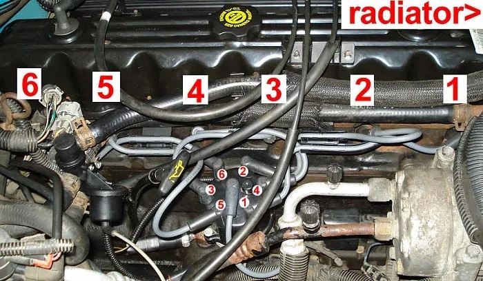
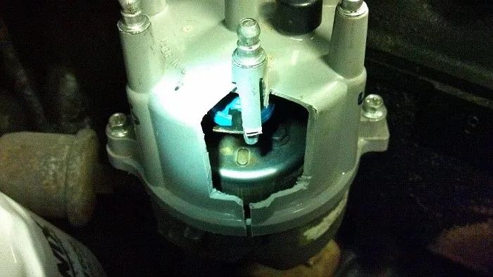
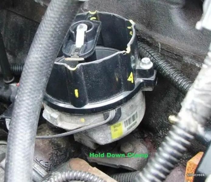
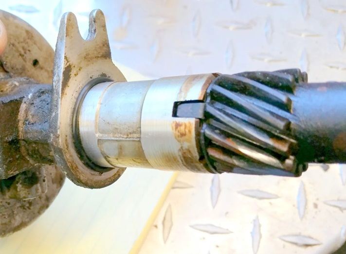
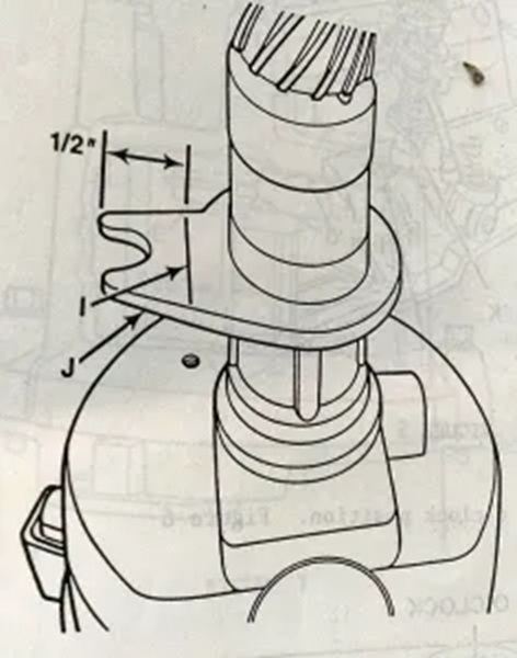
CRUISER'S MOSTLY RENIX TIPS DISTRIBUTOR INDEXING Remove the distributor cap and cut a “window” into the side of the distributor cap at the #1 spark plug wire post . The “window” should be large enough to allow easy visual inspection of the position of the distributor rotor at the #1 spark plug wire post. Reinstall the distributor cap. Use Tip 12 first to guarantee you’re on #1 TDC. Install a ¾” wrench or socket onto the vibration damper retaining bolt. Rotate the engine in a clockwise direction until the #1 cylinder is at top dead center. Align the timing mark on the vibration damper with the “0” degree mark on the front cover timing scale. The tip of the distributor rotor should be near the #1 spark plug wire post. Disconnect the distributor electrical connection. Remove the distributor holddown clamp, holddown bolt and distributor. Remove the distributor cap and rotor. Place the distributor housing upside down in a soft jaw vise. Scribe a line 1/2 inch from the end of the distributor locating tab. Cut the distributor locating tab at the scribed line with a saw. Remove any burrs and metal filings from the distributor. Reinstall rotor. If necessary, using a flat blade screwdriver, turn the oil pump gear drive shaft until the slot is slightly past the 11 o’clock position. The oil pump gear drive shaft is accessible through the distributor mounting bore in the engine block. A little tip here. Rather than use a dizzy gasket, use an o ring instead. NAPA #727-2024. Visually align the modified locating tab area of the distributor housing with the holddown clamp bolt hole. Turn the rotor to the 4 o’clock position. Lower the distributor into the engine block until it seats. The rotor should now be very close to the 5 o’clock position. Reinstall the distributor cap with the cutout “window”. Rotate the distributor housing until the trailing edge of the distributor rotor tip is just departing from the #1 spark plug wire post terminal . Reinstall the distributor holddown clamp and bolt.. Reinspect the position of the rotor to the #1 spark plug wire post to insure that it has not moved. Install the new distributor cap, reconnect the distributor electrical connections. HERE’S WHY DISTRIBUTOR INDEXING IS SO IMPORTANT: Distributor indexing explained: For clarification though, that’s not a cam sensor inside the Renix dizzy. It’s there to fire the injectors sequentially with the firing order. You’ll never notice if it went bad because the ECU will try to “guess” where it is and does a heck of a job at it. As for the “timing”, it is controlled by the ECU. Ever notice how wide the tip of the rotor is? Try and wrap your head around this: When the ECU yells “Fire” to the ignition control module, where is the rotor in relationship to the dizzy terminal? Not to the terminal yet? Past the terminal too far? What happens to the spark/secondary ignition strength when it has to jump the Grand Canyon in comparison to shooting from a rotor tip? Poor ignition performance, bucking, jerking, longer crank times. The factory was aware of this and issued a Technical Service Bulletin on it. This Tip, #13, is a condensed version of that factory TSB. You wouldn’t believe how many we found out of whack when I worked at the dealership. Yours is probably messed up also. RARELY did we find one set accurately. Use Tip 12 first to guarantee you’re on #1 TDC. Revised 08-19-19
-
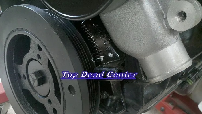
CRUISER'S MOSTLY RENIX TIPS SETTING YOUR 4.0 TO #1 TDC With #1 spark plug removed, turn the engine over clockwise using the 3/4″ front crankshaft bolt. You will see the degree marks on your front cover and you will see the timing mark on the balancer. Mark them with chalk or white-out. While turning the engine over, put your finger/thumb over #1 spark plug hole. As the mark on the balancer approaches the marks on the front cover, if you are coming up on #1 TDC, pressure in the cylinder will push on your finger. If there’s no pressure, you’re at #6 TDC and need to crank the engine over until you see the marks coming together and you get pressure. Set the mark on the balancer to the 0 mark on the front cover. Revised 1-31-2016
-
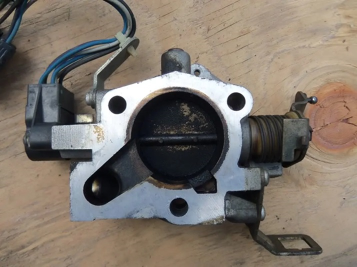
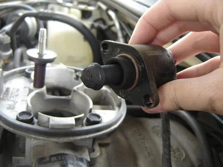
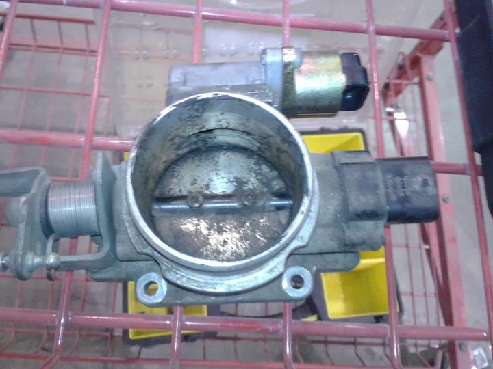
CRUISER'S MOSTLY RENIX TIPS THROTTLE BODY AND IAC CLEANING Originally by TJWalker of CherokeeForum & JeepForum The Idle Air Control (IAC) is mounted on the back of the throttle body (front for ’87-’90). The valve controls the idle speed of the engine by controlling the amount of air flowing through the air control passage. It consists of a stepper motor that moves a pintle shaped plunger in and out of the air control passage. When the valve plunger is retracted, the air control passage flows more air which raises the idle speed. When the valve plunger is extended, the air control passage flows less air which lowers the idle speed. Over time and miles, the IAC can get carboned up which can have an adverse affect on idle quality. Cleaning the IAC may restore proper function and is an easy procedure to perform and good preventive maintenance so it is never a bad idea. This should be part of a normal tune-up procedure and whenever idle/stalling issues are present. CLEANING THE JEEP 4.0 IDLE AIR CONTROL Remove the air filter cover, associated hoses and the rubber boot that goes from the air filter cover to the throttle body. Remove the IAC with a Torx driver (2 bolts; one can be kind of hard to get to). On ’91 and later, it may be easier to just remove the whole throttle body. Be sure to use a new throttle body to manifold gasket when reinstalling. “Gently” wiggle out the IAC from the throttle body. Gasket/O-ring on the IAC can be re-used if it is not damaged Clean the IAC with a spray can of throttle body cleaner; inexpensive and available at any place that sells auto parts. Throttle body cleaner is recommended rather than carburetor cleaner as it is less harsh, safe for throttle body coatings and oxygen sensors. Use cleaner, a rag and a toothbrush and or Q-Tips. Be gentle; don’t twist or pull on the pintle that protrudes from the IAC as it is fragile and you could damage it. Thoroughly spray clean and flush where the IAC seats in the throttle body with the same spray cleaner. It is also a good idea to clean the entire throttle body bore itself, the butterfly valve inside of the throttle body and it’s edges, and all associated linkage as long as you have things disassembled. Revised 1-31-2016
-
Another MJ launch coin
fiatslug87 replied to fiatslug87's topic in Craigslist/Marketplace/eBay... i.e. Not Your Stuff
-
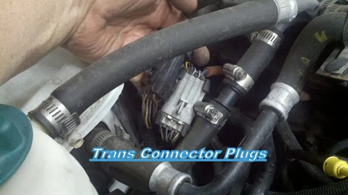
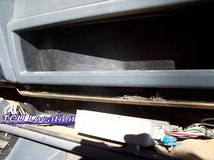
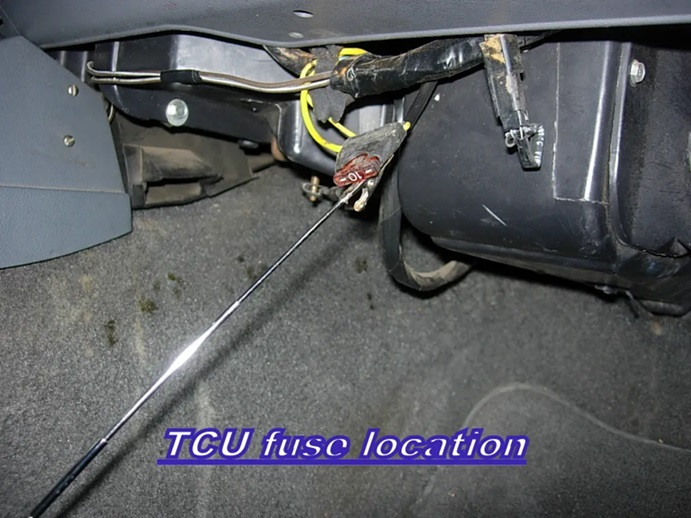
CRUISER'S MOSTLY RENIX TIPS TRANSMISSION CONNECTOR REFRESHING Over near the transmission dipstick tube are 2 rather large connectors. One is black and goes to the NSS and the gray connector goes to the transmission itself. These 2 connectors carry all the info between TPS, TCU, NSS, speed sensor, and transmission solenoids. Unplug each one, visually inspect for corrosion or bent pins, spray them out with electrical contact cleaner and plug them back in. Additionally, if your Jeep is an ’87 to ’90 Renix, it’s always a good idea to reach up under the glovebox area and unplug the connector to the TCU and spray it out along with the receptacle of the TCU. While you’re there, find the fuse right in that area for the TCU. Remove it and spray out it’s receptacle and clean any corrosion from the fuse. Revised 1-31-2016
-
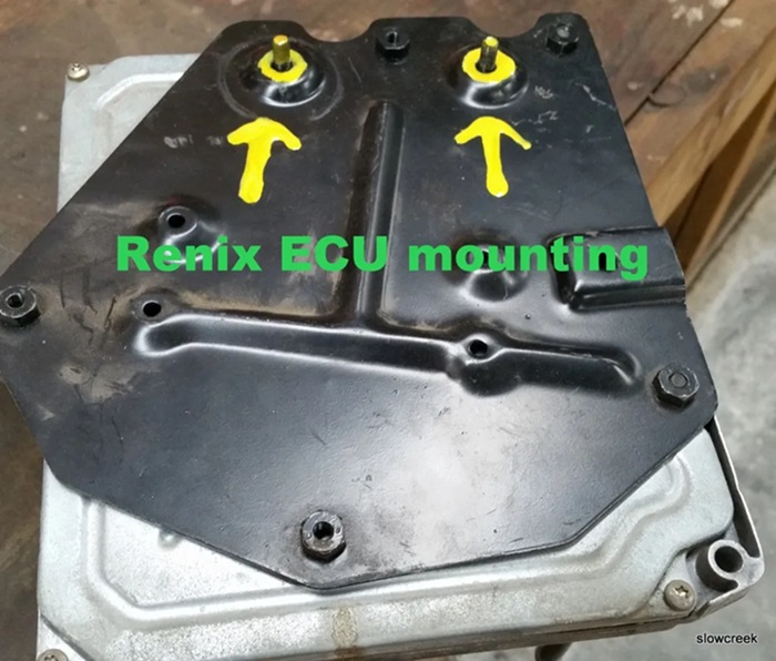
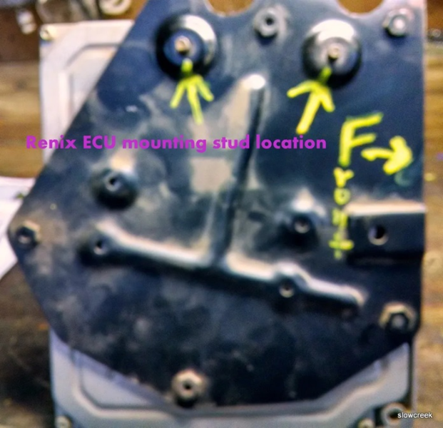
CRUISER'S MOSTLY RENIX TIPS RENIX ECU CONNECTOR REFRESHING Many times, when other fixes have failed, it becomes necessary to eliminate the ECU to harness connections as a cause. This requires removing the ECU. Up under the dash, to the right of the steering column is the ECU mounted to a black bracket. The bracket is held in place by two 10mm nuts to the underside of the dash. It’s most easily removed using a ratcheting wrench but a socket will work. Once you get the ECU down, unplug the two harness connectors from it. Visually inspect the connectors and pins. Using a good quality electronics cleaner, liberally spray both of the harness ends and the ECU pin area. Now, take a small pick or a dental tool and go to the harness connectors. Using the tool, tweak each female receptacle in the harness plugs so they will grasp the ECU pins more tightly. Plug the harnesses back on to the ECU and reinstall it. Revised 1-31-2016
-
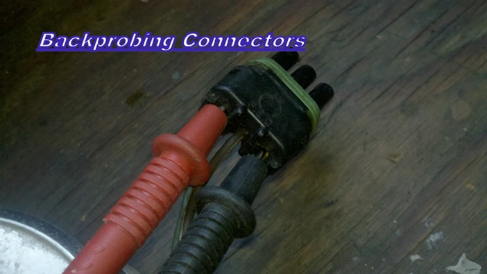
CRUISER'S MOSTLY RENIX TIPS RENIX TPS ADJUSTMENT Before attempting to adjust your TPS, there are a few things that need to be done. Be sure the throttle body has been recently cleaned. It’s especially important that the edges of the throttle butterfly are free of any carbon build-up. With the KEY OFF, and using the positive (red) lead of your ohmmeter, set on the lowest scale, probe the B terminal of the flat 3 wire connector of the TPS. The letters are embossed on the connector itself. Touch the black lead of your meter to the negative battery post. Wiggle the wiring harness where it parallels the valve cover and also over near the MAP sensor on the firewall. If you see more than 1 ohm of resistance, or fluctuation in your ohms reading, some modifications to the sensor ground harness will be necessary. The harness repair must be performed before proceeding. It is covered in detail in Tip 6. TPS ADJUSTMENT FOR ENGINE ISSUES Both Renix manual and automatic transmission equipped XJs and MJs have a flat three-wire connector to the TPS which provides data input to the ECU. The three wires in the connector are clearly embossed with the letters A, B, and C. Wire “A” is positive. Wire “B” is ground. DO NOT UNPLUG THE CONNECTORS! KEY ON, measure voltage from “A” positive to “B” ground by back-probing the connectors. Note the voltage reading–this is your REFERENCE voltage. KEY ON, back-probe the connector at wires “B” and “C”. Measure the voltage. This is your OUTPUT voltage. Your OUTPUT voltage needs to be seventeen percent of your REFERENCE voltage. For example: 4.82 volts X .17=.82 volts. Loosen both T-20 Torx screws attaching the TPS to the throttle body and rotate the TPS until you have achieved your desired output voltage. Tighten the screws carefully while watching to see that your output voltage remains where it is supposed to be. If you can’t achieve the correct output voltage, replace the TPS and start over. Sometimes, after adjusting your TPS the way outlined above, you may experience a high idle upon starting. If that happens, shut the engine off and reconnect your probes to B and C. Start the engine and while watching your meter, turn the TPS clockwise until the idle drops to normal and then rotate it back counterclockwise to your desired output voltage. TPS ADJUSTMENT FOR AUTOMATIC TRANSMISSION ISSUES Renix automatic transmission-equipped XJs and MJs have a TPS with two connectors. There is a flat three-wire connector, same as the manual transmission vehicles have, and it is tested the same as outlined above—FOR ALL ENGINE MANAGEMENT RELATED ISSUES. However, the automatic TPS also has a square four-wire connector, clearly embossed with the letters A,B,C, and D. It only uses three wires and provides information to the Transmission Control Module. THIS SQUARE FOUR WIRE CONNECTOR IS USED FOR TRANSMISSION/SHIFTING RELATED ISSUES ONLY. First off, DO NOT UNPLUG THE CONNECTORS! KEY ON, measure voltage between “A” positive and “D” ground by back-probing the connector. Note the voltage. This is your REFERENCE voltage. Back-probe the connector at wires “B” and “D”. Measure the voltage. This is your OUTPUT voltage. Your OUTPUT voltage needs to be eighty-three percent of your REFERENCE voltage. For example 4.8 volts X .83=3.98 volts. Adjust the TPS until you have achieved this percentage. If you can’t, replace the TPS and start over. So, if you have an automatic equipped XJ your TPS has two sides–one side feeds the ECU, and the other side feeds the TCU. For those with a MANUAL TRANSMISSION–the TPS for the manual transmission XJs is stupid expensive. You can substitute the automatic transmission TPS which is reasonably priced. The square 4 wire connector is just not used. Revised 7/08/17