


cruiser54
-
Posts
9413 -
Joined
-
Last visited
-
Days Won
14
Content Type
Profiles
Forums
Gallery
Everything posted by cruiser54
-

What are these relays for ?
cruiser54 replied to AMC86Kid's topic in MJ Tech: Modification and Repairs
So, you have a relay without the plug? -
What are these relays for ?
cruiser54 replied to AMC86Kid's topic in MJ Tech: Modification and Repairs
I have seen horn relays labelled with the letters. -
What are these relays for ?
cruiser54 replied to AMC86Kid's topic in MJ Tech: Modification and Repairs
HBS Horn Battery Switch -
What are these relays for ?
cruiser54 replied to AMC86Kid's topic in MJ Tech: Modification and Repairs
CRUISER'S MOSTLY RENIX TIPS HEADLIGHT HARNESS UPGRADE NOVEMBER 17, 2015 SALAD 54 COMMENTS It’s easy to install a supplemental headlight harness. From the factory, the voltage to the headlight bulbs travels from the battery, through connectors, inside the cabin, to the headlamp switch, and then back out to the lamps via undersized wire and more connectors. It’s not uncommon to find only 10.5 volts at the lamps. The supplemental harness is installed so that it provides battery voltage to the lamps and is just triggered by the factory wiring. The result is about 35% brighter headlamps and headlight switches that don’t melt and burn out. Here’s a link to a harness on ebay: http://www.ebay.com/itm/CERAMIC-H4-HEADLIGHT-RELAY-WIRING-HARNESS-2-HEADLAMP-LIGHT-BULB-SOCKET-PLUGS-7-/330997592807 Absolutely plug and play: Remove grille and headlamp bulbs. I fed my harnesses from the passenger side starting between the battery and the back of the headlamp housing, over to the driver side. Plug the driver side bulb into the new harness. Attach the new harness’s ground wire under one of the small bolts on the radiator support after scraping the paint off under it. Attach the harness to the existing harness behind the grille working toward the passenger side. Plug the new harness plug into passenger headlamp. Plug original headlamp plug into receptacle on new harness. Attach the ground for the passenger side just like you did the driver side under a radiator support bolt. Attach relays with provided bracket on the passenger side inner fender. Connect power wires to battery. -
Not normal sound. the ballast resistor was to reduce the VERY slight hiss from the pump at idle......most folks never heard it before the resistor.
-
What are these relays for ?
cruiser54 replied to AMC86Kid's topic in MJ Tech: Modification and Repairs
White is horn. -
HO exhaust manifold on a Renix
cruiser54 replied to JMO413's topic in MJ Tech: Modification and Repairs
EGR delete makes no difference. -
HO exhaust manifold on a Renix
cruiser54 replied to JMO413's topic in MJ Tech: Modification and Repairs
Your choice. 91 and later stock location is fine. -
HO exhaust manifold on a Renix
cruiser54 replied to JMO413's topic in MJ Tech: Modification and Repairs
Bolts right up to the head. MAY have to do minimal filing on the intake manifold. No biggie.
-
This works on the Renix 4.0s, but I don't know for sure about the 2.5s. CRUISER'S MOSTLY RENIX TIPS RENIX OIL FILTER TO SAE FILTER JANUARY 3, 2016 CRUISER54 9 COMMENTS Tired of having a poor selection of oil filters for your Renix Jeep? Limited availabilty a pain for you? 20mm threads? We don’t need mumblemeter threads on our oil filters. Here’s a simple mod that allows you to use the very popular SAE threaded oil filters which are more readily available. The old standard 3/4″ SAE thread. You can purchase a new oil filter nipple from the dealer for under $10 and never be bothered again. Part number 53007563AB. It’s the one on the left. Or, grab one off a 91 and later XJ at the junkyard. Be forewarned though. You need a 7/8 wrench to remove a Renix nipple, but a 15/16 wrench for the later style. And just in case you need to replace your oil filter adapter o-rings, here’s a handy guide. Oil Filter Adapter O-Ring Sizes 87-90 Renix Model O-rings 0.799 x 0.103 AS568 size -117 1.296 x 0.139 AS568 size -219 2.484 x 0.139 AS568 size –230 Dealer Part Numbers for Renix. Sold individually: 33002970, 33002971, 33002972 Renix kit from Crown Automotive-33002970K 91-01 HO Model Orings 0.676 x 0.070 AS568 size -017 0.859 x 0.139 AS568 size -212 2.484 x 0.139 AS568 size -230
-
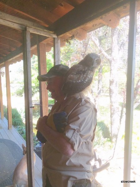
I wonder where those stands are made..........
-
-
-
Headlights, running lights, and taillights
cruiser54 replied to Zander.gil's topic in MJ Tech: Modification and Repairs
CRUISER'S MOSTLY RENIX TIPS CONNECTOR AND RELAY/RECEPTACLE REFRESHING OCTOBER 30, 2015 SALAD 24 COMMENTS EDIT I suggest unplugging EVERY electrical connection in the engine bay you can find, whether engine related or not, and spraying it out with a good electronics cleaner, visually inspecting the terminals making sure they haven’t retracted into the plastic holder, and then plugging it back together. There’s a critical 10-pin connector for the front lighting system located in front of the air cleaner and behind the left headlight assembly. Don’t miss that one. Also be sure that the connectors to the ballast resistor mounted near the air cleaner housing are clean and tight. ALL of the relays should be removed, the terminals wire-brushed until shiny, and the receptacles sprayed out with contact cleaner. Then plug them back in. I do this on every Renix Jeep I purchase or work on for someone else. Revised 1-31-2016 -
Headlights, running lights, and taillights
cruiser54 replied to Zander.gil's topic in MJ Tech: Modification and Repairs
If it were mine, I would do the following first. BTW, did you know the interior lights rotate up and down? CRUISER'S MOSTLY RENIX TIPS RENIX GROUND REFRESHING OCTOBER 30, 2015 SALAD 46 COMMENTS EDIT The Renix era XJs and MJs were built with an under-engineered grounding system for the engine/transmission electronics. One problem in particular involves the multiple ground connection at the engine dipstick tube stud. A poor ground here can cause a multitude of driveabililty issues, wasted time, failed emission tests, and wasted money replacing components unnecessarily. All the components listed below ground at the dipstick tube stud: Distributor Sync Sensor, TCU main ground, TCU “Shift Point Logic”, Ignition Control Module, Fuel Injectors, ECU main ground (which other engine sensors ground through, including the Oxygen sensor, Knock Sensor, Cruise Control and Transmission Sync signal. All extremely important stuff. The factory was aware of the issues with this ground point and addressed it by suggesting the following: Remove the nut holding the wire terminals to the stud. Verify that the stud is indeed tightened securely into the block. If the whole stud turns, you can use a 7/32″ six point socket or wrench to hold it so the nut can be removed. Worst case, cut the wires and remove the stud and nut. Install new terminal eyelets on the wires when going back together. Scrape any and all paint from the stud’s mounting surface where the wires will attach. Surfaces must be clean, shiny and free of any oil, grease, or paint. Inspect the wire terminals. Check to see that none of the terminals are crimped over wire insulation instead of bare wire. Be sure the crimps are tight. It wouldn’t hurt to re-crimp them just as a matter of course. Sand and polish the wire terminals until clean and shiny on both sides. Apply a liberal coating of OxGard, which is available at Lowe’s and other stores. Reinstall all the wires to the stud and tighten the nut down securely. While you’re in that general area, locate the battery negative cable which is fastened to the engine block just forward of the dipstick stud. Remove the bolt, scrape the block to bare metal, clean and polish the cable terminal, apply OxGard, and reattach securely. Another area where the grounding system on Renix era Jeeps was lacking is the engine to chassis ground. There is a braided cable from the back of the cylinder head that also attaches to the driver’s side of the firewall. This cable is undersized for its intended use and subject to corrosion and poor connections at each end. Remove the cable end from the firewall using a 15mm wrench or socket. Scrape the paint off down to bare metal and clean the wire terminal. Apply OxGard. Reattach securely. Remove the other end of the cable from the rear of the head using a 3’4″ socket. Clean all the oil, paint and crud from the stud. Clean the wire terminal of the cable and reattach securely with a liberal coating of OxGard. 2 STRONG suggestions regarding the ground system: I prefer to add a #4 gauge cable from the firewall to a bolt on the rear of the intake manifold, either to a heat shield bolt or fuel rail bolt. A cable about 18″ long with a 3/8″ lug on each end works great and you can get one at any parts store already made up. NAPA has them as part number 781116. A further improvement to the grounding system can be made using a #4 cable, about 10″ long with 3/8″ terminals at each end. Attach one end of this cable to the negative battery bolt and the other end under the closest 10mm headed bolt on the radiator support just forward of the battery. NAPA part number 781115. For those of us with Comanches, it’s very important to remove the driver’s side tail lamp assembly to access the ground for the fuel pump. Remove the screw holding the black ground wire. Scrape the paint from the body and corrosion from the wire terminal. Add a 10 gauge wire, with an eyelet on each end, from that grounding point to a bolt on the frame. Better yet, on both Cherokees and Comanches, complete Tip 29 for the best fuel pump grounding. Be sure to scrape all mounting points to bare metal and apply OxGard also. If you want to upgrade your ground and battery cables with custom made parts, contact Neal at www.meanlemons.com -
Cruiser's Mostly Renix Tips
cruiser54 replied to cruiser54's topic in MJ Tech: DIY Projects and Write-Ups
thanks for the kind words. -
Weird Idle/Startup: Known Issues
cruiser54 replied to Dammerung's topic in MJ Tech: Modification and Repairs
CRUISER'S MOSTLY RENIX TIPS RENIX TPS ADJUSTMENT OCTOBER 30, 2015 SALAD 144 COMMENTS Before attempting to adjust your TPS, there are a few things that need to be done. Be sure the throttle body has been recently cleaned. It’s especially important that the edges of the throttle butterfly are free of any carbon build-up. With the KEY OFF, and using the positive (red) lead of your ohmmeter, set on the lowest scale, probe the B terminal of the flat 3 wire connector of the TPS. The letters are embossed on the connector itself. Touch the black lead of your meter to the negative battery post. Wiggle the wiring harness where it parallels the valve cover and also over near the MAP sensor on the firewall. If you see more than 1 ohm of resistance, or fluctuation in your ohms reading, some modifications to the sensor ground harness will be necessary. The harness repair must be performed before proceeding. It is covered in detail in Tip 6. TPS ADJUSTMENT FOR ENGINE ISSUES Both Renix manual and automatic transmission equipped XJs and MJs have a flat three-wire connector to the TPS which provides data input to the ECU. The three wires in the connector are clearly embossed with the letters A, B, and C. Wire “A” is positive. Wire “B” is ground. DO NOT UNPLUG THE CONNECTORS! KEY ON, measure voltage from “A” positive to “B” ground by back-probing the connectors. Note the voltage reading–this is your REFERENCE voltage. KEY ON, back-probe the connector at wires “B” and “C”. Measure the voltage. This is your OUTPUT voltage. Your OUTPUT voltage needs to be seventeen percent of your REFERENCE voltage. For example: 4.82 volts X .17=.82 volts. Loosen both T-20 Torx screws attaching the TPS to the throttle body and rotate the TPS until you have achieved your desired output voltage. Tighten the screws carefully while watching to see that your output voltage remains where it is supposed to be. If you can’t achieve the correct output voltage, replace the TPS and start over. Sometimes, after adjusting your TPS the way outlined above, you may experience a high idle upon starting. If that happens, shut the engine off and reconnect your probes to B and C. Start the engine and while watching your meter, turn the TPS clockwise until the idle drops to normal and then rotate it back counterclockwise to your desired output voltage. TPS ADJUSTMENT FOR AUTOMATIC TRANSMISSION ISSUES Renix automatic transmission-equipped XJs and MJs have a TPS with two connectors. There is a flat three-wire connector, same as the manual transmission vehicles have, and it is tested the same as outlined above—FOR ALL ENGINE MANAGEMENT RELATED ISSUES. However, the automatic TPS also has a square four-wire connector, clearly embossed with the letters A,B,C, and D. It only uses three wires and provides information to the Transmission Control Module. THIS SQUARE FOUR WIRE CONNECTOR IS USED FOR TRANSMISSION/SHIFTING RELATED ISSUES ONLY. First off, DO NOT UNPLUG THE CONNECTORS! KEY ON, measure voltage between “A” positive and “D” ground by back-probing the connector. Note the voltage. This is your REFERENCE voltage. Back-probe the connector at wires “B” and “D”. Measure the voltage. This is your OUTPUT voltage. Your OUTPUT voltage needs to be eighty-three percent of your REFERENCE voltage. For example 4.8 volts X .83=3.98 volts. Adjust the TPS until you have achieved this percentage. If you can’t, replace the TPS and start over. So, if you have an automatic equipped XJ your TPS has two sides–one side feeds the ECU, and the other side feeds the TCU. For those with a MANUAL TRANSMISSION–the TPS for the manual transmission XJs is stupid expensive. You can substitute the automatic transmission TPS which is reasonably priced. The square 4 wire connector is just not used. -
88 comanche hard start or no start when cold
cruiser54 replied to ctxj93's topic in MJ Tech: Modification and Repairs
Thanks for the update!! -
Cranking SPEED is important to the Renix system. The CPS generates a signal to the eCU. Slow crank= low signal.
-
Weird Idle/Startup: Known Issues
cruiser54 replied to Dammerung's topic in MJ Tech: Modification and Repairs
Any improvement? Probably oughta check the TPS adjustment now. -
Probably a bad TPS or a varying ground on that circuit.
-
none
-
Doesn't have to be just for an 87. 87 to 90 interchange.
-
well, I'll be dipped.
-
I just went out and looked in both an 89 and a 92 FSM. The ONLY mention of a lower hose spring is for the 5.9 engine in a Grand Wagoneer or J body truck.