


ghetdjc320
-
Posts
5212 -
Joined
-
Last visited
-
Days Won
1
Content Type
Profiles
Forums
Gallery
Everything posted by ghetdjc320
-
So the 90+ calipers are not an upgrade on the front D30 and are not compatible. The 89- knuckles used a bolt on caliper while the 90+ switched to a floating caliper with cast in pad “wings”. The 89- has man my upgrade options depending on the wheel size you have. You need at least 16’s to do anything special. The stock brake setup isn’t bad either, just don’t use hard pad compounds (like pure ceramic). Grab Centric posi-stop pads along with centric rotors and calipers for your model year axle. It’s plenty for a stock ish rig up to about 31’s. Don’t go with drilled or slotted rotors either as your just loosing a bit of pad contact area. Save those for street cars with oversized brakes. Keep the master cylinder stock bore size as well. Even the stock booster will work fine if the vacuum is sufficient at idle.
-
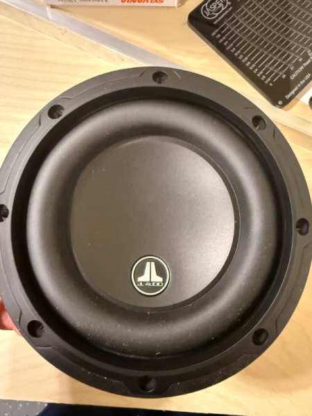
Just keep in mind that there aren't many subs that can fit under the stock curved base seat mounting frame. Pioneer used have a nifty little unit but they discontinued it. I ran a hideaway 8 for some time but that was under the corbeau seat brackets.
-

What CC knows about stock Jeep radios
ghetdjc320 replied to NickyV's topic in MJ Tech: DIY Projects and Write-Ups
Here is a clarification of the audio signal path for reference: the 7 pin connector between the main board and preamp when viewed from left to right below are as follows: 1. Audio channel output from main board 2. Audio channel output from main board 3. Unknown, but likely a low voltage or reference line - will test to verify 4. tape deck channel output from preamp potentiometer 5. Signal ground 6. Tape deck channel output from preamp potentiometer 7. 12v positive for tape deck door illumination So the switching logic is happening inside the main board. Tape, AM and FM radio are all switched on the main board and sent to the preamp on pins 1 and 2. The tape audio comes into the preamp board first, then goes through a pair of potentiometers to set the signal level first before it’s sent to the main board. Since I’m not using the tape deck so this opens up the ability to loop the tuner input through the tape inputs to attenuate the signal down to reduce/eliminate the bleed through signal. So that would look like pins 1 and 2 out from main board 7 pin connector to tape input L and R inputs on the preamp board. Then disconnect pins 4 and 6 from the main board 7 pin connector and route them to the preamp inputs that correspond to the main board 7 pin connector pins 1 and 2. This would allow you to use the two potentiometers on the preamp to attenuate the level of the tuner. It seems like a small transistor here could solve the issue of the auto switching to the aux inout as well. I’ll investigate that possibility.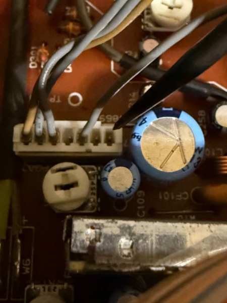
-
Which screw goes here, and what are these screws?
ghetdjc320 replied to jodawill's topic in MJ Tech: Modification and Repairs
Ok, that’s an awesome product!! Very clever solution to a very common problem. Do you know if these would also fit the b pillar trim upper screw hole? The one just above the courtesy light. -
My suggestion is to ditch the b pillar speakers and run the Kicker CX 4 channel amp. It’s one of the best bang for buck options out there and is a class AB amp which has a very smooth volume response. The infinity speakers you have don’t need much power as they have fairly high sensitivity (volume output per watt of input). With that 4 channel amp, you bridge the rear two channels to a small sub. For a budget system, I’d go with a 6.5” bazooka behind one of the seats. That pairs well with the front door speakers and will give you excellent bang for buck while taking up little space and fitting nicely behind the seat on the floor. What I can say is, don’t mount any subs to the center rear wall of the MJ. The frequency response there is atrocious and the rear glass will take the vibration. For your door speakers, some sound dampening around them will do wonders for how they sound. For most sub 400w 4 channel amps, they will require at least a 8awg amp kit. This will depend somewhat on amplifier type. Class D will use less power than class AB and so forth. As Derf said, always install the appropriate sized fuse near the battery. As for the B pillar speakers, swapping to a larger speaker back there meets with several issues. First, there is no baffle for the speaker there. You will loose a great deal of frequency response b cause the sound waves from the front and rear of your speaker are colliding all over the place in those b pillars. And since they are out of phase with each other, they cancel each other out. Also, they are behind your seat and throw off the front stereo sound stage. And being behind the seats, only lower frequencies will be able to make it to your ears. Amp: https://www.crutchfield.com/p_20646CX36T/Kicker-46CXA360-4T.html Sub: https://www.crutchfield.com/p_204BT6DVC/Bazooka-BT6024DVC.html There is some simple wiring that will need to be done between the amp and sub the amp is rated for 65w per channel at 4ohms for the fronts and the rear two channels can be bridged into a single 180w 2ohm output which perfectly matches that sub. Kicker even sells a little bass knob for that amp to control the sub gain for those two rear channels.
-
Which screw goes here, and what are these screws?
ghetdjc320 replied to jodawill's topic in MJ Tech: Modification and Repairs
Sounds like something @boxyjeep might offer. Otherwise, the interior screw assortment from Dorman works very well, granted, there will be several in the kits that isn’t used. -
Which screw goes here, and what are these screws?
ghetdjc320 replied to jodawill's topic in MJ Tech: Modification and Repairs
The Dorman GM interior trim screw kits have that screw in their assortment. I bought several of those kits and have been able to use them all around the jeep for trim screws. -
Yep, both my 90 and 91 were eliminators with buckets
-
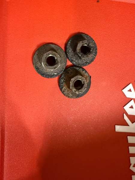
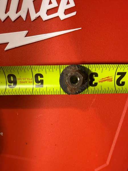
Here are the originals on my 90. They are the same as my 91 as well. Larger washer than I see on the ones in the pics above.
-
Project “Tomahawk”
ghetdjc320 replied to ghetdjc320's topic in MJ Hardcore Tech: Epic Journeys to Greatness
-
What CC knows about stock Jeep radios
ghetdjc320 replied to NickyV's topic in MJ Tech: DIY Projects and Write-Ups
So I’m going to build out a 2nd version of this radio. Here is the plan: I’ll install a Qualcomm Bluetooth board and an Analog Devices ADAU1701 chip. This radio will have AM/FM tuner, AptX 5.1 Bluetooth and a full DSP. I will tune this DSP for the Comanche cab acoustics in my Tomahawk. I’ll program the DSP to auto switch over to Bluetooth when active and switch back over to radio when not in use. This way I can default back and retain radio functions while absolutely 100% eliminating any radio bleed-through. If I get really ambitious, I’ll configure the “play” button to control the play/pause on the Bluetooth chip since the tape player will be gone. On another note, I have a couple of probably good tape players if anyone wants one. I do want to come up with a better solution for the button feel as well. There is a decent bit of slack. Adding felt to the buttons themselves would indeed make them stand out better but would still leave a decent gap to the actual contact pad on the front panel board. If I find what I’m looking for, it should quiet down the key presses and bring the buttons forward a bit for a better feel. -
The ones on my 90 have a captured washer that’s a bit larger than the one in the pic
-
What CC knows about stock Jeep radios
ghetdjc320 replied to NickyV's topic in MJ Tech: DIY Projects and Write-Ups
Just to confirm, those two end cables in that connector above are indeed the tuner L/R for the AM & FM. When viewing the white 7 pin connector as in the picture above, starting at the left side, pin 1 is Left channel pin 2 is Right channel. This is on an RX173 radio but looking at the older RX I have here, I believe this pinout logic is the same. -
This one popped up recently: https://www.facebook.com/share/p/1EUNrSKCKr/?
-
Spring is nice but flash floods can be an issue. October/November can be nice as well. The cooler weather can be a bit of a benefit when climbing off-road.
-
New carpet in as I redo the interior.
ghetdjc320 replied to OzarkGuy's topic in MJ Tech: Modification and Repairs
@boxyjeep has a nice setup: https://boxyjeep.com/products/jeep-cherokee-xj-ax-15-tunnel-cover-1984-2001 -
New carpet in as I redo the interior.
ghetdjc320 replied to OzarkGuy's topic in MJ Tech: Modification and Repairs
Looking good! If you can, get a build thread going so you can document your progress along the way. Also, I would emphatically suggest you make sure there are zero water leaks in the cab before buttoning everything back up -
My 1990 Wiper Repair
ghetdjc320 replied to AnotherOldJeepGuy's topic in MJ Tech: Modification and Repairs
The “Park” feature is a function of the motor itself. I’d check your grounds. You may have some continuity but you may not be able to pass enough current to keep that circuit alive and finish the sweep. -
Check with @boxyjeep. He offers a lot of gauge cluster parts and I’d bet he has one.
-
Nice looking truck! Always liked the look of the “Chief” graphics. I’ll take a crack at some of the questions: 1. There is no insulation in the crossmember. The cross member design does have several sandwiched pieces of metal that can indeed get moisture and oxidation traps, but the crossmembers were typically galvanized (one of the very few pieces on MJ’s) and normally hold up decently. They are fairly lightweight and still solid enough for their use. 2. First off, your XJ is getting rather phenomenal MPG so the comparison might be a bit off. 16 mpg for a lifted 4x4 MJ with a 4.0 is very normal and typically within range. What is interesting though is that you noticed it wasn’t getting as warm as your XJ. If indeed the gauge is accurate, a rich running engine will get lower MPG & typically runs cooler. A renix engine monitor or REM can be a really handy tool to help you see what the ecu is doing and can sometimes help track down issues. 3. If the turn signals were working then went out as you drove with the headlights on, my bet is that it’s the sockets and/or bulbs themselves. I’d remove all the sockets, clean them, add some dielectric grease and swap in some new incandescent bulbs.
-
Installing DynaPad around the hump
ghetdjc320 replied to jodawill's topic in MJ Tech: Modification and Repairs
That stuff is quite different to Dynapad. The Silas stuff is similar to Dynamat which is typically a thin aluminum skin with Butyl or similar backing. The Dynapad is a heavy and thick insulation type material. -
What CC knows about stock Jeep radios
ghetdjc320 replied to NickyV's topic in MJ Tech: DIY Projects and Write-Ups
This is the stock am/fm radio line input from the main board to the preamp board. Now we know the audio path which looks to be the same across the RX series of radios. You can entirely disconnect this 7 pin connection which runs from the main board to the preamp but you will loose your tone controls and a bit of gain. There was no perceptible background noise difference either way so I left it connected to maintain tone controls but de-pinned the am/fm tuner. This head unit will be just a pure source unit with nothing but a clean aux signal. I’ll term this more of a “hifi” unit. But I have another RX-173 I’ll convert to a multi purpose unit and may even retain the tape player as I can see now how to cleanly integrated aux and eliminate any bleed through without disabling the tuner section. Most of the information o have seen referenced only indicates that the AM radio bleeds through. I can see why that is the assumption as the am radio gain is fairly high. But once you reduce that gain and unify it to the fm gain, you’ll notice that there is still tune bleed in both am and fm bands. To test this, connect your aux source, pause the music, and turn your radio volume to max. Likely you will hear the bleed through. I’ll try to identify which of these pins does what but for now, this is a simple way to defeat the tuner bleed and remove the signal from the path altogether.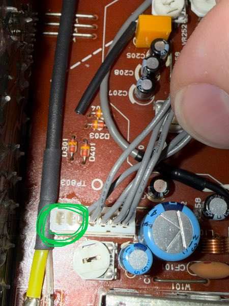
-
Installing DynaPad around the hump
ghetdjc320 replied to jodawill's topic in MJ Tech: Modification and Repairs
Cut it into pieces as Pete mentioned. Personally, I only use dynapad on horizontal surfaces so I don’t run it up the sides of the tunnel. I use a couple of layers of dynamat for vertical areas followed by dynaliner. The dynapad is phenomenal stuff but can make it hard to install carpet if you get it on the areas where the carpet has to bend or curve such as the tunnel hump. Installing dynapad around the frame caps on the floor works excellent. Don’t be afraid to cut your the shapes you need instead of trying to use it as a continuous uncut piece. Also, give yourself some gaps around the seat belt anchors, and specially the outboard ones in the rocker panels. Those are already tough to get to with just the carpet there. -
What CC knows about stock Jeep radios
ghetdjc320 replied to NickyV's topic in MJ Tech: DIY Projects and Write-Ups
Wanted to provide a quick update. I tested the aux input today and it works perfectly with zero perceptible interference or noise. However, if I pause the music and turn up the volume all the way, I am still able to make out radio signals. I don’t think anyone would ever know but that’s just unacceptable to me. So I still have to rid this radio of that interference. Will trace those lines and see what can be done. Now that I’ve eliminated the tape deck, I may just eliminate the tuners as well. It would just leave me with an empty shell of a radio but It would be a pure source for the system. It would be easy to add Bluetooth as well and I may still retain that as an option. It is handy to have a radio still but the audio tap method does not duck it far enough for my liking. I need that signal cut, not just hiding in the background somewhere. -
Looking forward to what you come up with. I ended up having to daily drive my MJ for almost a year and that totally changed the way I mod it now.