


Ωhm
-
Posts
3166 -
Joined
-
Last visited
-
Days Won
6
Content Type
Profiles
Forums
Gallery
Everything posted by Ωhm
-
 I have some of these (license plate). Let me know if you want one. PM your address.
-
Can We Talk About Radios?… Again?
Ωhm replied to neohic's topic in MJ Tech: Modification and Repairs
Not sure if this could help, but Volvo used a suppression capacitor for radio interference. No help with capacitor value (Farad). ICM_EARLY RENIX VOLVO_2.pdf -
OUCH!
-
Need some thoughts(solved, fuel pump 2.5L)
Ωhm replied to eaglescout526's topic in MJ Tech: Modification and Repairs
86 ECU looks for WOT switch input. 89 harness connect to a Power Steering Pressure Switch for same input. This is a difference. Not sure if it would cause your issues. -
Idiot lights gauges 1986 COMANCHE 2.5L
Ωhm replied to SLOTMAN's topic in MJ Tech: Modification and Repairs
I believe both BRAKE & COOLANT are "Bulb Check" bulbs. Meaning both should illuminate during ENGINE START when KEY is in the CRANK position. Purpose is to make sure both bulbs test GOOD prior to every drive cycle. -
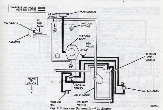
Other photo showed elbow at manifold connection. Looks correct in latest photo. Taken from RELEARN procedure: The following general procedures are to be used if drivability problems are encountered after power loss or battery has been disconnected. These procedures may provide an aid in eliminating these problems. 88 FSM Computer Relearn Procedures.pdf
-
Make sure that additional hose (Fuel Pressure Regulator (FPR)) is connected at the intake manifold. Can't tell by photo. Idle may get better with time (RELEARN) after all your fixes. May need time here (drive cycles) to see if things improve.
-
Thinking maybe metal and heat related. 2¢
-
This shows the general area where the vacuum hose goes. That broken tab (green) can/will cause problem later on. Take note.
-
You ain't going anywhere with that MAP sensor hose disconnected. Should connect up at the base of TB. Look for the other missing end. What's that green thing laying on the heat shield?
-
1986 2.5L to 3.4L: Amateur Hour
Ωhm replied to FigurativeGarbage's topic in Member Projects: Your Comanches
RED wire with single connector, if HOT AT ALL TIMES, is used for Engine Compartment Lamp, when equipped. Two YEL wires could be Resistor Pack for Automatic Transmission. Relay Block with Two PNK wires is/was B+Latch Relay. -
Swap your relays around with one another. See if different trouble follows the relays. Splice_A (Engine Harness) is common point for all four (4) circuits (FP motor, Ballast Resistor, O2 relay and Starter relay). One of your Ballast Resistor wires will lead you to this splice, the other wire back to the other side of vehicle.
-
The ECU controls the FP relay at KEY ON and ENGINE RUNNING. This is the source for B+ to Ballast Resistor to Fuel Pump motor. When ECU see NO start signal (KEY ON only) at C201_C3 (Starter (+)) circuit, ECU will time out and shut FP relay OFF (prime cycle).
-
Three conditions feed (B+) to the fuel pump motor. One (1) using the ballast resistor and two (2) bypassing the ballast resistor. Conditions are as follows: 1. During CRANK. B+ is supplied by the Starter Relay. Ballast resistor is bypassed. 2. During WOT. ECU knows when vehicle is in WOT and activates the 02 Heater Relay. Ballast resistor is bypassed. 3. At all other times, Fuel Pump Relay supplies B+ using the Ballast resistor in series with the fuel pump motor circuit.
-
Part# J536 0059
-
Is he missing the sleeve and spacer(s)?
-
Wire Over Driver's Shoulder Above Seatbelt?
Ωhm replied to NickyV's topic in MJ Tech: Modification and Repairs
True. It's for the Cargo Box Lamp, if equipped. -
Find this posting further up this page. Try downloading that.
-
BLK should find chassis GND thru G102 at all times. BLK/WHT should find GND thru door jamb switches with open door(s) or when headlamp switch is set for interior lights ON.
-
Didn't know website was contact by email only. Happy the part number helped.
-
Here's one source. Maybe other sources out there. Euramtec
-
-
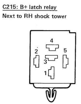
B+ Latch Relay is a tough circuit to figure out. B+ Latch Relay will have two (2) pink wires in C215_4 and C215_5. Use this to help with ID. KEY OFF Check for voltage at C215_1. Looking for 12vdc (HOT at all times).
-
Were wires ever poked with a testlight or DVOM needle probe?