


llhat
-
Posts
236 -
Joined
-
Last visited
Content Type
Profiles
Forums
Gallery
Everything posted by llhat
-
glad it is back... that video, it would make me believe 'dragging starter' from days of yore.... wonder what the amperage draw was? had to be 'up there' to pull down that much... no way it was creating enough engine rpm for the computer to detect and engage quickly even though it 'caught' and ran at the end of video.
-
think covered in the PDF above " start" ......
-
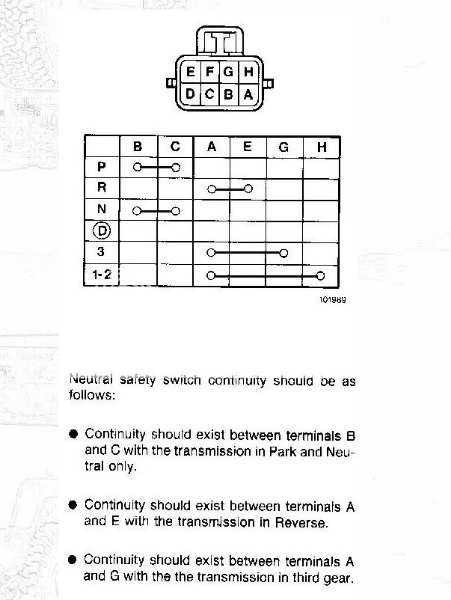
sorry for that red herring on the NSS connector... it looked 'right' from the image. Did you click and open the PDF files i attached above.. the one named 'start' may be of assistance.
-
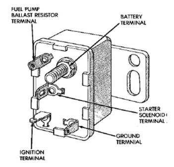
that may be the connector to the NSS on the AW4 transmission... that could also cause a no-start you will probably need the wiring diagram eventually.... 7way female.pdf 7way.pdf start.pdf
-
Fuel system venting - high level of vacuum in tank
llhat replied to 87MJTIM's topic in MJ Tech: Modification and Repairs
my 89 long bed tank has two recesses in the top of the tank, in the recesses are holes, there is a rubber grommet and a fitting inserted. attached to each fitting is a small hose, these meet at a 'tee' and proceed forward to the charcoal canister under the hood... these hoses should be visible on each side of the port for the fuel filter. ensure these hoses are not kinked is the first step... from there... dunno.... -
Adding a Fog Light Harness: what to look for?
llhat replied to Salvagedcircuit's topic in MJ Tech: Modification and Repairs
Just today received a coupon email from HF and that harness is in the list... think 20bux or so... coupon good a couple of weeks. -
THANK YOU for those details, will be giving this a shot !
-
so far, how has the clear vinyl tubing mated up with the combustion gases, fuel, etc? Would 1/4" vacuum hose be an improvement?
-
ok, I can see the larger OD hose... and seems like a doable thing. i thought though the restriction was in the grommet and not in the hose ( white 'nipple) I'd also guess you did not change the nipple screwed into the intake manifold? IIRC the HO change-over utilized a larger nipple on the intake, as well as an even larger hose. I've been on a process of cleaning my 'original' design hose with more frequency... instead of each oil change.
-
care to expand more on this? did you do a write up?
-
Cooling/gauges/electrical many questions
llhat replied to Snowstorm87MJ's topic in MJ Tech: Modification and Repairs
i added a housing to my 89 for a mechanical gage... almost wish i had not. to start with, the supplied adapter screwed in OK, but the bulb for the gage would not seal as the bulb itself bottomed out in the housing and the nut on the bulb would not tighten down. I obtained an adapter that got me the height, but i believe the bulb is not fully immersed in the coolant. running I believe it is about 15 degrees low. when I stop, the gage will increase from heat soak. now if i had used an electric gage, the sensor would probably directly thread in the housing. maybe on a project that drains the block, I'll move the bulb for the mechanical gage.... maybe not. -
Another Battery thread, oh boy!
llhat replied to NC Tom's topic in MJ Tech: Modification and Repairs
so a group 34 over the standard ?? group 58? I can see the spec comparison 500+ CCA versus 800 CCA for the group 34... so the dimensions are the same? have a wally group 58 dated 2021, so at some point I know i'll have to update also... try to drive it more often to keep a charge on it... but still probably less than 2k/ year. -
Jeep 4.0 Automatic not changing gears.
llhat replied to Gradinen's topic in MJ Tech: Modification and Repairs
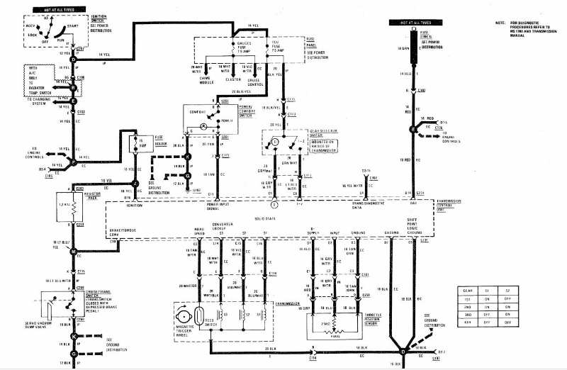
read in the link I provided, there are some diagrams in the attachments and some tips from Ohm on some of the pin-out voltages, connections. -
Jeep 4.0 Automatic not changing gears.
llhat replied to Gradinen's topic in MJ Tech: Modification and Repairs
Memory of 'my' issue... and @ohm's help... The Solenoid for 1'st gear is being energized if you start out in D and the vehicle readily moves... I drove mine for some time manually shifting the gears, just not getting overdrive and remembering to shift down at stops. the non shift could "possibly" be in the TCU, not instructing the gear 2 solenoid to energize.... I would have to go back and study the posts between Ohm and I and review some of the wiring diagrams.. there is no board level diagram for the TCU. would suggest testing the solenoids for resistance values.... even if you remove the pan to do so... Unsure IF this could be speed sensor related, and what the TCU does with that input. another point... the cable adjustment at the throttle body.. IIRC it mostly controls the line pressure, or am I incorrect on this point... ??? link to my old post.. -
Jeep 4.0 Automatic not changing gears.
llhat replied to Gradinen's topic in MJ Tech: Modification and Repairs
yes, but think the in-line is 10a, located near the TCU mounting location under the lower dash panel. -
Jeep 4.0 Automatic not changing gears.
llhat replied to Gradinen's topic in MJ Tech: Modification and Repairs
Partially true, the AW4 when controlled by the TCU does shift through the solenoids, when using the column lever, the shifter engages a manual valve, shifting the 'gears', but no overdrive (4th) or 2nd, or the converter lockup. what happens if the OP tries to start movement in "D", if there's an issue with electronic shifting, the transmission will try to start in 3rd gear and it won't like it. -
MayDay!! - Hard Accel Killed Idle
llhat replied to AnotherOldJeepGuy's topic in MJ Tech: Modification and Repairs
the directional control for the hvac uses that small vacuum line, BUT the vacuum canister behind the front bumper if cracked can do the same thing. i had my doubts on the muffler would fix it... -
be sure to check that vinyl hose frequently, combustion gases may have a reaction with it. Can agree on your principle of getting more flow, that original hard plastic line is small... the Later HO versions used a much larger line on the rear Valve Cover port... there is a thread somewhere on here for that mod... I just have not attempted it yet.. It used the HO rear grommet... and larger line as well as larger nipple on intake port. I frequently remove my small line and spray brake keen or choke cleaner through it...
-
i believe what you are showing in the picture is actually #22, not #24 IF i understand that image to be at bottom of the bell housing.... IF it is #22, it can be removed, hammered out a bit and reinstalled. IF confirmed to be #24, don't think i would be too concerned with it.
-
Should I replace these suspension parts?
llhat replied to AnotherOldJeepGuy's topic in MJ Tech: Modification and Repairs
i cannot tell in the image... but by your description of the actions on removal, the nut was of the thread distortion / deformation type, and a lock nut. typically these nuts have some pressure placed on them after threading to 'smoosh' the top few threads. to me, if the new nuts have nyloc design, use them. I do not think they are vastly superior or anything, but will work, and you've got them. -
Should I replace these suspension parts?
llhat replied to AnotherOldJeepGuy's topic in MJ Tech: Modification and Repairs
there are different types of lock nuts, some with the nylon insert that locks, others use some type of deformation to the nut to create interference either as a deformation at the 'top' of the nut where the bolt would stick through, or there could be some type of knurl or 'teeth' on the face of the nut flange.... -
Does anyone make the front Iner protective fender?
llhat replied to Javelinmania's topic in MJ Tech: Modification and Repairs
difficulty level on install? what has to be removed? I saw a listing for a pair... mine have broken apart over years... -
Should I replace these suspension parts?
llhat replied to AnotherOldJeepGuy's topic in MJ Tech: Modification and Repairs
metric or sae, do not use a cheep bolt !! ensure they are grade marked, grade 8 for sae, corresponding for metric and are of the same design, shoulder, thread length, head style ( integral washer ) -
On the positive terminal of battery follow the small gauge wire to the area under the relay cover. think you will find a suitable location to connect you + power wire for that harness. there's a place there with multiple fusible links connected for power.
-
Fuel smell only when tank is filled
llhat replied to robfg67's topic in MJ Tech: Modification and Repairs
could be as eaglescout suggest, takes only a gallon or few to get below sender access hole... recently went through this a few months ago on a NEW sender the O ring had deteriorated within months of new install... changed o-ring vendor and 'so far' OK other area are the two vapor line access on TOP of the tank... there's a valve up there connected to two vacuum lines leading to charcoal canister under hood. the lines could be rotten or have dislodged. the valves are retained with a rubber grommet also... you say no drips, that is also good... and bad for diagnosis check fuel fill also on fender side of tank.