
fiatslug87
-
Posts
7354 -
Joined
-
Last visited
-
Days Won
8
Content Type
Profiles
Forums
Gallery
Everything posted by fiatslug87
-
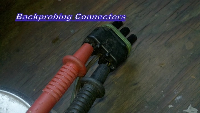
CRUISER'S MOSTLY RENIX TIPS RENIX SENSOR GROUND TEST The sensor ground circuit affects the CTS, TPS, IAT, MAP, ECU and diagnostic connector grounds. It’s very important and not something to overlook in diagnosing your Renix Jeep as it is common for the harnesses to have poor crimps causing poor grounds. If any or all of the sensors do not have a good ground, the signal the ECU receives from these sensors is inaccurate. Set your meter to measure Ohms. Be sure the ignition is in the OFF position. Using the positive (red) lead of your ohmmeter, probe the B terminal of the flat 3 wire connector of the TPS . The letters are embossed on the connector itself. Touch the black lead of your meter to the negative battery post. Wiggle the wiring harness where it runs parallel to the valve cover and also near the MAP sensor mounted on the firewall. If you have an 87 or 88 with the C101 connector mounted on the firewall above the brake booster, wiggle it, too. You want to see as close to 0 ohms of resistance as possible. And when wiggling the harnesses/connectors the resistance value should stay low. If there is a variance in the values when wiggling the wires, you have a poor crimp/connection in the wiring harness or a poor ground at the engine dipstick tube stud. Refreshing of the dipstick tube connection is covered in Renix Ground Refreshing, and the sensor ground upgrade is covered in Tip #6 – Sensor Ground Upgrade. On 87 and 88 models, you could have a poor connection at the C101 connector as well. See Tip #2 – C101 Refreshing and Tip #27 – C101 Elimination. Revised 1-31-2016
-
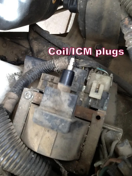
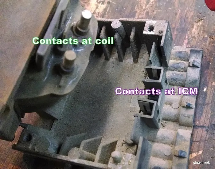
CRUISER'S MOSTLY RENIX TIPS RENIX ICU/COIL CONTACT REFRESHING The contacts between the coil and the ICU on your Renix Jeep can become corroded and loose causing a complete or intermittent no-start condition. I recommend the following procedure as a maintenance precaution to insure this is eliminated as a possible cause now and in the future. The coil is attached to the ICU by two T20 Torx bolts. Remove these two bolts and lift the coil up off the ICU. You will see 2 pins and 2 sets of contacts. Clean both the pins and springy contact pieces with a good electronics cleaner and some fine sandpaper. Squeeze the springy contacts closer together with some needle nose pliers. Apply some OxGard to the contacts. Bolt the coil back on to the ICU. While you’re right there, unplug the connectors from the ICU and inspect the pins in the harness connector. Make sure the pins are not retracted into the connector. Spray out the connector and the receptacle of the ICU with the same good electronics cleaner you used earlier. I feel this procedure should be performed at least once in the lifetime of a Renix Jeep. Revised 5-11-16
-
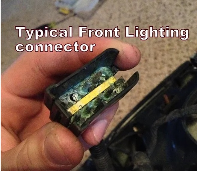
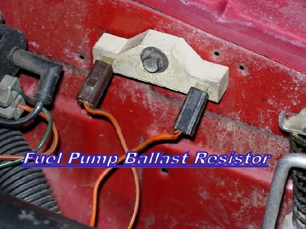
 CRUISER'S MOSTLY RENIX TIPS CONNECTOR AND RELAY/RECEPTACLE REFRESHING I suggest unplugging EVERY electrical connection in the engine bay you can find, whether engine related or not, and spraying it out with a good electronics cleaner, visually inspecting the terminals making sure they haven’t retracted into the plastic holder, and then plugging it back together. There’s a critical 10-pin connector for the front lighting system located in front of the air cleaner and behind the left headlight assembly. Don’t miss that one. Also be sure that the connectors to the ballast resistor mounted near the air cleaner housing are clean and tight. ALL of the relays should be removed, the terminals wire-brushed until shiny, and the receptacles sprayed out with contact cleaner. Then plug them back in. I do this on every Renix Jeep I purchase or work on for someone else. Revised 1-31-2016
-
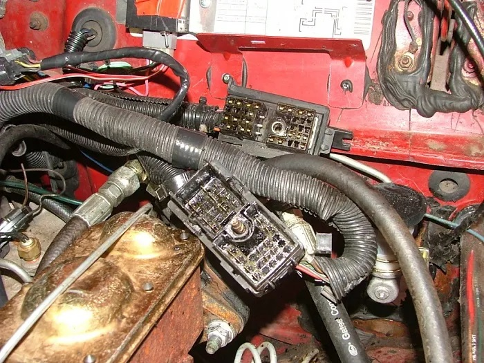
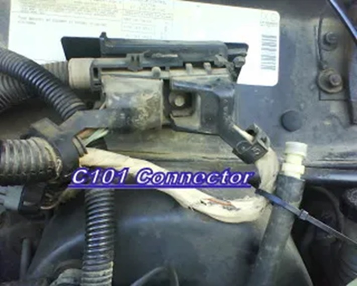
CRUISER'S MOSTLY RENIX TIPS RENIX C101 CONNECTOR REFRESHING The C101 connector on 1987 and 1988 Renix Jeeps was a source of electrical resistance when the vehicles were new. So much so that the factory eliminated this connector in the 1989 and 1990 models. The factory recommended cleaning this connector to insure the proper voltage and ground signals between the ECU and the fuel injection sensors. We can only imagine how this connector has become a larger source of voltage loss and increased resistance over a period of more than 25 years. The C101 connector needs to be cleaned at least once in the lifetime of your vehicle. Chances are it’s never been done before. Almost every critical signal between the engine sensors, injectors, ECU, and some to the TCU, travel this path through the C101 connector. That said, the cleaning described below is a real MUST DO right off the bat for any new-to-you Jeep. But, I strongly advocate eliminating the C101 at some point by following the procedure with photos and video in Tip 27. Soldering skills are required and it takes about an hour and a half. The C101 connector is located on the driver’s side firewall above and behind the brake booster. It is held together with a single bolt in it’s center. To get the connectors apart, simply remove the ¼” bolt and pull the halves apart. You will find the connector is packed with a black tar-like substance which has hardened over time. Take a pocket screwdriver or the like and scrape out all the tar crap you can. Follow up by spraying out both connector halves with brake cleaner and then swabbing out the remainder of the tar. Repeat this procedure until the tar is totally removed. This may require 3 or more repetitions. Wipe out the connectors after spraying with a soft cloth. If you have a small pick or dental tool, tweak the female connectors on the one side so they grab the pins on the opposite side a bit tighter before bolting both halves back together. If you wish to eliminate this connector entirely (highly recommended), see Tip #27 – C101 Elimination Revised 1-31-2016
-
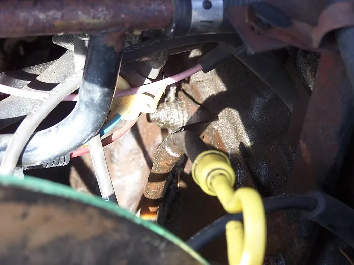
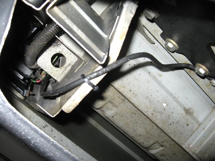
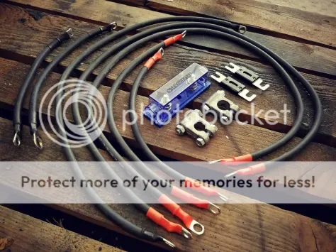
CRUISER'S MOSTLY RENIX TIPS RENIX GROUND REFRESHING The Renix era XJs and MJs were built with an under-engineered grounding system for the engine/transmission electronics. One problem in particular involves the multiple ground connection at the engine dipstick tube stud. A poor ground here can cause a multitude of driveabililty issues, wasted time, failed emission tests, and wasted money replacing components unnecessarily. All the components listed below ground at the dipstick tube stud: Distributor Sync Sensor, TCU main ground, TCU “Shift Point Logic”, Ignition Control Module, Fuel Injectors, ECU main ground (which other engine sensors ground through, including the Oxygen sensor, Knock Sensor, Cruise Control and Transmission Sync signal. All extremely important stuff. The factory was aware of the issues with this ground point and addressed it by suggesting the following: Remove the nut holding the wire terminals to the stud. Verify that the stud is indeed tightened securely into the block. If the whole stud turns, you can use a 7/32″ six point socket or wrench to hold it so the nut can be removed. Worst case, cut the wires and remove the stud and nut. Install new terminal eyelets on the wires when going back together. Scrape any and all paint from the stud’s mounting surface where the wires will attach. Surfaces must be clean, shiny and free of any oil, grease, or paint. Inspect the wire terminals. Check to see that none of the terminals are crimped over wire insulation instead of bare wire. Be sure the crimps are tight. It wouldn’t hurt to re-crimp them just as a matter of course. Sand and polish the wire terminals until clean and shiny on both sides. Apply a liberal coating of OxGard, which is available at Lowe’s and other stores. Reinstall all the wires to the stud and tighten the nut down securely. While you’re in that general area, locate the battery negative cable which is fastened to the engine block just forward of the dipstick stud. Remove the bolt, scrape the block to bare metal, clean and polish the cable terminal, apply OxGard, and reattach securely. Another area where the grounding system on Renix era Jeeps was lacking is the engine to chassis ground. There is a braided cable from the back of the cylinder head that also attaches to the driver’s side of the firewall. This cable is undersized for its intended use and subject to corrosion and poor connections at each end. Remove the cable end from the firewall using a 15mm wrench or socket. Scrape the paint off down to bare metal and clean the wire terminal. Apply OxGard. Reattach securely. Remove the other end of the cable from the rear of the head using a 3’4″ socket. Clean all the oil, paint and crud from the stud. Clean the wire terminal of the cable and reattach securely with a liberal coating of OxGard. 2 STRONG suggestions regarding the ground system: I prefer to add a #4 gauge cable from the firewall to a bolt on the rear of the intake manifold, either to a heat shield bolt or fuel rail bolt. A cable about 18″ long with a 3/8″ lug on each end works great and you can get one at any parts store already made up. NAPA has them as part number 781116. A further improvement to the grounding system can be made using a #4 cable, about 10″ long with 3/8″ terminals at each end. Attach one end of this cable to the negative battery bolt and the other end under the closest 10mm headed bolt on the radiator support just forward of the battery. NAPA part number 781115. For those of us with Comanches, it’s very important to remove the driver’s side tail lamp assembly to access the ground for the fuel pump. Remove the screw holding the black ground wire. Scrape the paint from the body and corrosion from the wire terminal. Add a 10 gauge wire, with an eyelet on each end, from that grounding point to a bolt on the frame. Better yet, on both Cherokees and Comanches, complete Tip 29 for the best fuel pump grounding. Be sure to scrape all mounting points to bare metal and apply OxGard also. If you want to UPGRADE YOUR GROUND AND BATTERY CABLES with custom made parts, contact Paul at www.jeepcables.com Revised 02/04/2017
-
This is very sad to hear. He was a wealth of knowledge and always very helpful. RIP Cruiser.
-
eBay link
-
What date would we put if we were in the Yahoo group?
-
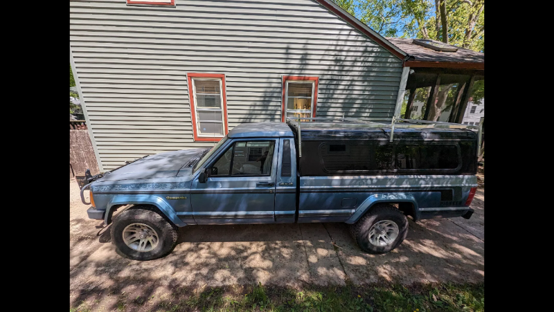
On eBay in Madison, WI asking $15K OBO.
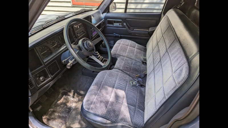
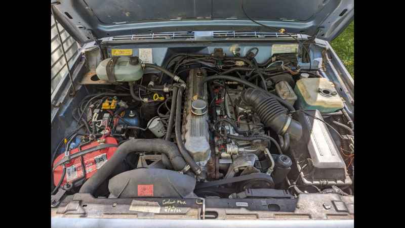
-
Charcoal Canister - hose connections
fiatslug87 replied to Keri's topic in MJ Tech: Modification and Repairs
Just a straight tube with a beveled end comes out the bottom, doesn’t go anywhere. -
Nice! Thanks Eagle!
-
Ok, we need an annual update.
-
1975 Brutally Simple Daily Driver
fiatslug87 replied to neohic's topic in Member Projects: Other Cool Stuff
Wait, you know how to weld? -
Renix stuck in open loop
fiatslug87 replied to TheFerret55's topic in MJ Tech: Modification and Repairs
What’s the Ω reading between A and B on the O2 sensor? Should be 5-7Ω. -
On eBay in Oceanside, NY asking $3,000.
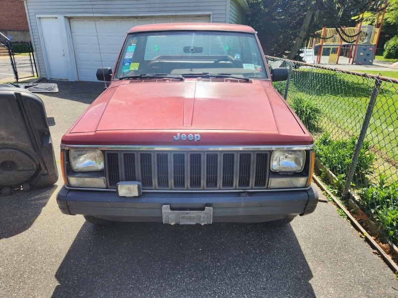
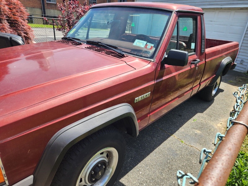
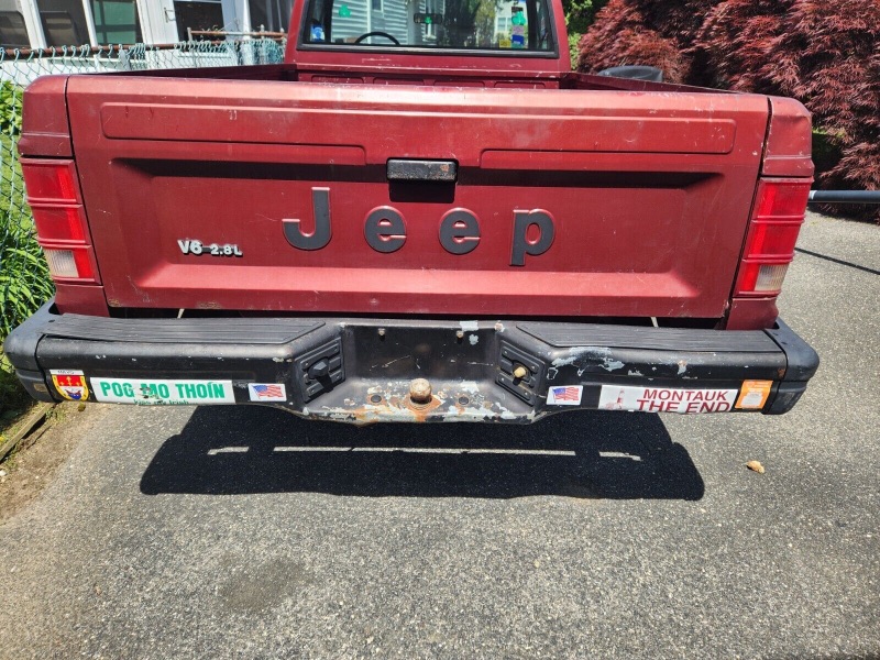
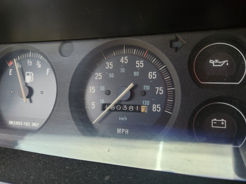
-
Load sensing valve. It changes rear brake pressure based on weight in the bed. That arm should attach to a bracket on the rear pumpkin through a rod. Many people delete it, here’s how to make it adjustable.
-
Congrats! Now get the MJ ready for next year!
-
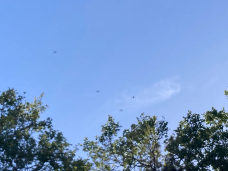
Four Ospreys flying overhead in San Jose , CA.
-
AWESOME!!! Please keep posting. I say keep going south. This will be you
-
Battery drain from Starter Relay?
fiatslug87 replied to EdJarHead's topic in MJ Tech: Modification and Repairs
The fog light relay stock configuration would be up by the radiator support above the air intake -
Battery drain from Starter Relay?
fiatslug87 replied to EdJarHead's topic in MJ Tech: Modification and Repairs
What Ωhm said. My neighbor’s battery kept dying, first thing I looked at and sure enough one of the screws had fallen out which made the switch pivot and not turn off. -
VIN Registry List: September 2026 Update
fiatslug87 replied to fiatslug87's topic in Comanche Registry (VIN decoding)
April 2024 update, see first post. 8 new additions this month for a total of 2265. -
Too many characters, VIN is probably 1JTHS6617GT082221
-
-
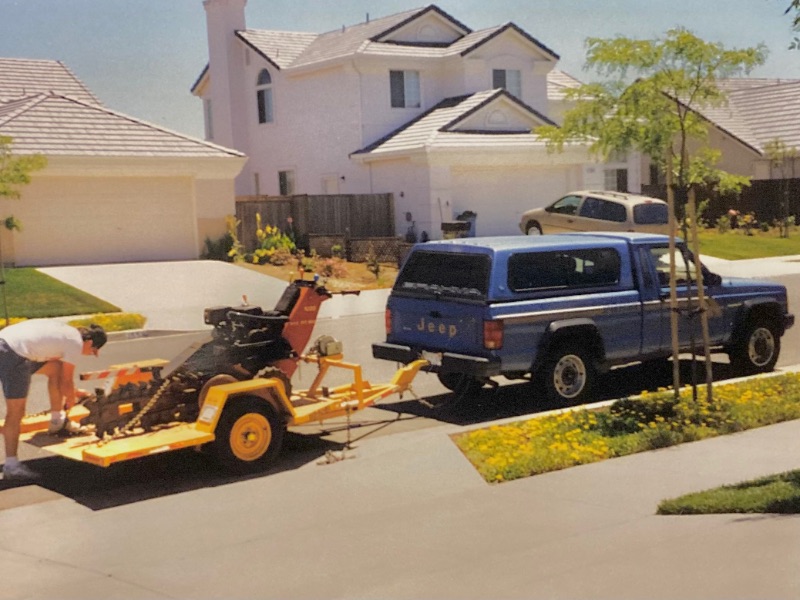
Blast from the past (pre trailer hitch )! Just came across this picture from August 1998, trenching for the backyard sprinkler system.