


JustEmptyEveryPocket
-
Posts
632 -
Joined
-
Last visited
-
Days Won
3
Content Type
Profiles
Forums
Gallery
Everything posted by JustEmptyEveryPocket
-
THESE are my personal favorites. Found them on my old 85 BJ73 Land Cruiser. Not sure if you can find them, but worth a search at least. They are easy to deal with, and I have never had one fail on that 3B engine. A brief search showed several auctions on eBay, so you should be able to find some if you are interested.
-
THIS THREAD is the best one to follow in my opinion. Good luck with the swap, its well worth it.
-
Need opinions on removing broken stud
JustEmptyEveryPocket replied to fiatslug87's topic in MJ Tech: Modification and Repairs
I would weld it personally. Hold a nut on the outside and fill it up with wire.Then let it cool a bit and wrench it out. -
Loose axle components?
JustEmptyEveryPocket replied to NC Tom's topic in MJ Tech: Modification and Repairs
My opinion: This is a great project to start with, if you want to work on your Comanche yourself. A basic socket set and a big hammer should be all that you need. Plus some PB Blaster or similar. Check out THIS video by BleepinJeep. Its a great walkthrough. THIS is another good video that will show you have to remove the front axle shafts. So like Pete said, watch some videos and see what you think you are up for. -
Dual diaphragm brake upgrade
JustEmptyEveryPocket replied to jeeptec1's topic in MJ Tech: Modification and Repairs
When I get around to doing the WJ swap I plan on doing something similar to Dasbulliwagen. However, I am going to use a die to cut threads on both the WJ brake arm and the piece cut from the original. That way I can use the stock brake light switch and literally dial in my pedal height. I figure to use a coupler and drill & tap it for two sets screws to keep things from moving when all is said and done. Also this way I don't have to mentally worry about my welding skills (which absolutely suck). -
Leak on fuse box
JustEmptyEveryPocket replied to WestonA's topic in MJ Tech: Modification and Repairs
Is your clutch master leaking onto it? Because if so you are gonna have a long road to get it running again. I think other members with this issue replaced the entire fuse box by re-pinning one wire at a time. And fixing any corrosion along the way obviously. Post back with a few more details like engine and trans and what type of leak you are talking about. -
Bouncing Speedo
JustEmptyEveryPocket replied to benjy_26's topic in MJ Tech: Modification and Repairs
Before replacing the cable, I would recommend reseating it at both the cluster and the transfercase. Mine has retreated down the outside sheathing so that it was not making good contact with the back of the gauge cluster. I took it apart at the transfercase and pushed it back towards the cluster while spinning it, then reassembled the transfercase end. Worked fine after that. While you have it apart, consider spraying in some dry lube spray like THIS product to help it spin freely. -
is Lucas Oil Stabilizer worth it?
JustEmptyEveryPocket replied to Deleted's topic in MJ Tech: Modification and Repairs
Here is my opinion: If you have nothing wrong and nothing to complain of, then don't try to fix it. Oil stabilizers are half @$$ fixes for big problems in my opinion. You may cause an issue by putting it into a clean running system. When you develop a problem, then come back and think about using Lucas, MOA, Marvel's Mystery Oil, etc. Until then, just keep up with regular maintenance and enjoy your ride. -
Rough running 4.0
JustEmptyEveryPocket replied to Knucklehead97's topic in MJ Tech: Modification and Repairs
For the signal, use a noid light. For the actual spray of the injector, not sure. -
Front Suspension Wizard Input Needed
JustEmptyEveryPocket replied to AZJeff's topic in MJ Tech: Modification and Repairs
If it was my money, I would buy adjustable arms. Like THESE. Then I could dial everything in myself. Personally, I set my caster to about 10 degrees. I know that ~7* is stock, but I like the road feel of a little more angle. This is only possible because I have adjustable uppers and lowers. Not everyone's cup of tea though. -
Front Suspension Wizard Input Needed
JustEmptyEveryPocket replied to AZJeff's topic in MJ Tech: Modification and Repairs
Eagle, I thought Hornbrod did the different sway bar mounts. Like THESE HERE. -
Renix 4.0 high warm idle
JustEmptyEveryPocket replied to RustyRodder's topic in MJ Tech: Modification and Repairs
Kjell: My guess would be the trick was unplugging and replugging the TPS connector. Probably helped seat a pin better or some such. Either that, or you have a 91 or 92 MJ with the HO motor. That ECU has adaptive memory. But Renix is basically a complex series of switches and nothing else, no memory anywhere, etc. OP: I would listen to Ohm and Cruiser54. They should get you to the answer soon. -
Renix 4.0 high warm idle
JustEmptyEveryPocket replied to RustyRodder's topic in MJ Tech: Modification and Repairs
Cleaning the connectors is an okay thing to do, just be careful if you use any solvents. No need to "reset" the ECU though. Renix does not have adaptive memory, so it doesn't do anything. Every time the engine starts up is like a brand new start from ECU perspective. -
1989 RWD 4.0L MJ/ Headlight Dimmer Location
JustEmptyEveryPocket replied to Dal3's topic in MJ Tech: Modification and Repairs
The the turn signal lever actuates a rod that follows the steering column down to a switch. This switch controls high beam operation. -
Any front end techs around?
JustEmptyEveryPocket replied to Eagle's topic in MJ Tech: Modification and Repairs
My $0.02: I would grab a tape, pick a point to measure from on each tire, and take measures from front tire to back tire on each side, RF tire to LR tire, and LF tire to RR tire. I would agree with JeepDriver that most likely your frame or axle is tweaked off, causing it to pull. -
WJ Brake Booster
JustEmptyEveryPocket replied to JustEmptyEveryPocket's topic in MJ Tech: Modification and Repairs
The only reason I haven't jumped in and done this already is because of that firewall molestation. Well that and I am lazy. *joking* Cruiser54, a lot or a little it is still truck molestation, just ask the catholic priests. Thanks for the idea Jeep Driver. Did you buttweld the two pieces of booster rod? Or sleeve them? And any chance you remember the thickness of your spacer? -
WJ Brake Booster
JustEmptyEveryPocket replied to JustEmptyEveryPocket's topic in MJ Tech: Modification and Repairs
Jeep Driver: How did you extend the rod? With your spacer, were you able to leave the lip of the firewall unmutilated? Eagle: The warning light was a nice bonus. I am not above running without it, but if I can have it all the better. -
My brakes have gotten bad (step on the pedal and it goes halfway to the floor and makes a terrible hissing sound). Anyways, I have an 01 WJ booster and master to install. As part of this I want to delete my Rear Height Sensor (its being tied up with string right now). Since I would be doing all this I want to re-run the brake lines themselves as they are starting to look kinda crusty. To simplify life I was thinking about getting THIS and removing the distribution block as well, and starting from fresh. Does anyone see a problem with doing this? Has anyone used this product before?
-
Minuit, Is the retaining rivet the one that gets ground off? Because I didn't think that stuck down far enough to keep these things in place.
-
Noob question here, looking for some basic explanations: My MJ has a Ford 8.8 rear end, and I have been working on the e-brake. At the same time, I am swapping to a 97+ XJ hand lever. Currently I have the cabling figured out, the handbrake in the cab figured out, and am down to the adjustments. Which is where the problems are. I have done the following: adjusted the star wheel in the 8.8 until I can barely get the rotor on, and it has drag when I spin it (I spin it down on the drivers side and up on the passenger side. Is this correct?) tightened the nut at the equalizer until the cables are taut pulled the hand brake up spun the rear tires to see if it is grabbing I have repeated all these steps 3-4 times and am not getting any results. Sometimes it seems that the ebrake is grabbing if I spin the tire backwards. Other times I completely lose any feeling of drag when I spin the tire. When I gave up tonight the adjuster seemed to be getting looser, not tighter. What am I missing? The only things I can think of are the initial parking brake pad adjustment followed by tightening the nut at the parking cable equalizer. So how can I tell if a). The pads are in enough contact with the rotor when the parking brake is NOT engaged b). The cables at the adjuster are "tight" enough. ie: how much slack or tension should there be? This is driving me crazy!
-
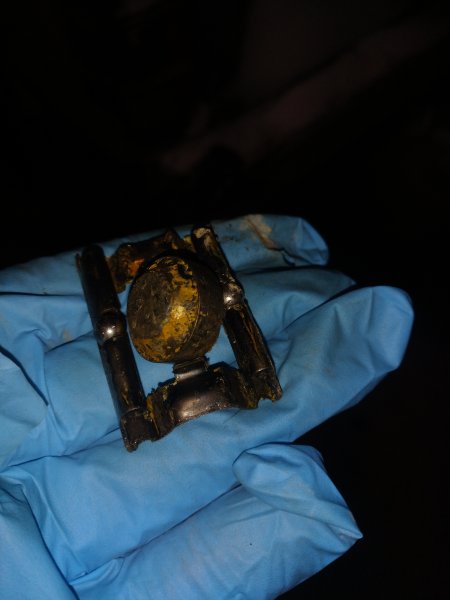
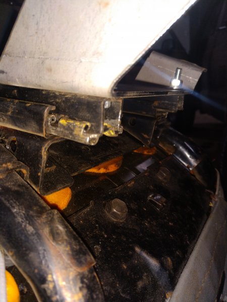
I found a pair of decent 90 2-door XJ seats. So I grabbed them and brackets from krustyballer and have been slowly working on installing them. The PO on my MJ installed some buckets seats by hacking up the original brackets and then using plywood to mount everything. There are no tracks, levers, springs, etc on my seats. Just the buckets, plywood, and cut to hell brackets. When I was drilling and grinding off the XJ brackets the pieces pictured below fell out. Where did they come from, what do they do, and how do I put them back where they go? Thanks!
-
There is always the DIY option, HERE. Costly to start, but gives you so many options down the road.
-
Dual Diagram Brake Booster
JustEmptyEveryPocket replied to Blaine.D's topic in MJ Tech: Modification and Repairs
HERE is a good write-up for the WJ. HERE is one for a 96 XJ. Its a project I have been needing to do for quite a while.Here is hoping for time this spring. -
B-Pillar Light Woes
JustEmptyEveryPocket replied to JustEmptyEveryPocket's topic in MJ Tech: Modification and Repairs
So I finally had some time to get back in and play around with this some more. First of all I took a new reading from the pink w/ black tracer wire that the light plugs into. Went from the wire back to the battery so I had a known good ground. It read 13 WAIT FOR IT mV. That is right, I must have misread it the first time around and I feel like a dumb@ss now. Went back to C118 connector (big thanks to Ohm for the help in reading the schematics) and checked voltage at the pink wire in the connector. It has 12.6V, and yes I tripled check to make sure it read V and NOT mV. Then I thought to measure resistance from the body side of the C118 connector's pink wire and the pink w/ black tracer in the b-pillar. When I hooked my meter on it, it started with a crazy high value (M-ohms), but then slowly came down and ended with 0 ohms. I take that to mean that the wire is complete, ie no breaks in it. Finally, as I was running out of ideas I ran a wire directly from the positive side of the battery to the pink w/ black tracer in the b-pillar to see what would happen. The lights came on! Unfortunately, they did not go off when the door switch was depressed, but stay on constantly in both the "door open" setting and when I switched the lens to "always on". If I switched the lens to the "off" position they went off like normal. So somewhere I am losing power to the wire. And possible have a problem with the door switch. But the power in is the big problem right now. Since I have power at the C118 connector, I need to trace the wire from there. Looking at the diagram on page 62 of the electrical manual Ohm linked, I need to find the "B" splice point. Anyone happen to know where that is? Anything else I need to check? Thanks again for all the help yall. -
B-Pillar Light Woes
JustEmptyEveryPocket replied to JustEmptyEveryPocket's topic in MJ Tech: Modification and Repairs
From my first post: I tested power back to the battery. Then I tested from the power wire to each of the ground wires at the b-pillar light. One of them gave me a constant 13V reading, and the other read 13V until I depressed the door switch, then it read nothing. I pulled the fuse today and it looked fine, no melting. So now I will try to trace the wires you are pointing me towards. Thanks for your help looking that up. I did ohm the ground wires measuring back to the battery. I don't remember the numbers exactly, but they were not over 10ohms. Plus, if I ran a test light from the red wire in the b-pillar through a bulb and back to negative on the battery then the bulb should light up. It didn't. This leads me to believe it is not a ground problem. Am I wrong with this idea? Granted, the ground may not be great, but I think there is a larger problem somewhere. Thanks for all the help so far guys.