

Ωhm
-
Posts
3196 -
Joined
-
Last visited
-
Days Won
6
Content Type
Profiles
Forums
Gallery
Everything posted by Ωhm
-
If you got a 4.0L: Using a voltmeter or 12vdc testlight (preferred) check for Battery_Voltage_(B+) on the following pins (use battery_negative terminal for ground): D1_5: B+ (Hot at all times) D2_4: B+ (Hot during KEY ON/CRANKING). D1_6: KEY ON (B+ (Hot for 2-3 seconds)) or CRANKING (B+ (Hot during CRANK)).

-
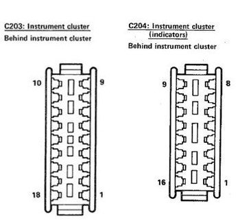
 Disconnect C156. Disconnect C203. Check for continuity between these two points (GRY/BLK) on the IP Harness side. I don't understand this testing. Connect C156. With C203 disconnected measure for voltage between C203_10(BLK) and C203_11(GRY/BLK) with KEY ON and Left Turn Signal ON. Looking for 12vdc_0vdc_12vdc_ect_ect. Try and select a 20vdc range on your DVOM. In other words, auto ranging OFF.
-
This is what makes me think we have a Voltage Drop. Plug/Unplug is a good thing for all these connectors. Voltmeters are not the best tool for finding Voltage Drops. A testlight will tax the circuit (dimly lit), if voltage drop exist on the circuit.
-
Looks like we could be chasing a Voltage Drop (VD). You need a simple 12vdc test light or just make one. Example: Test Light Find and disconnect C118. Make sure you have good contact between each of the pins. C118_4 - BLK C118_5 - RED (PNK) C118_9 - BLK/WHT

-
C115 - ECU to Instrument Panel (and one other)
Ωhm replied to Gojira94's topic in MJ Tech: Modification and Repairs
Thanks -
C115 - ECU to Instrument Panel (and one other)
Ωhm replied to Gojira94's topic in MJ Tech: Modification and Repairs
Now what I don’t know is C260 serves as a dual function switch. One is electrically for the purpose of disengaging the auto trans torque converter and the other is a mechanical vacuum dump for the cruise control (if equipped). So the question is, does the clutch pedal need the cruise/trans switch if you’re a Manual Trans with Cruise Control? Myself, IDK. Anyone with this setup (MT wCC)? -
C115 - ECU to Instrument Panel (and one other)
Ωhm replied to Gojira94's topic in MJ Tech: Modification and Repairs
88Electrical Manual Connector#1: C115. Pg19_2.5L/Pg20_4.0L. Connector#2: C260. Same pages as above. I think I see a clutch pedal. -
-
Looks like they should work. Using jumper wires, if necessary, can you get any 12vdc incandescent bulb to work properly? Try this: When the LEDs are ON (dimly), measure voltage across the bulb, one end to the other. Should show ≈12vdc (battery voltage).
-
I agree, any automotive 12vdc5W incandescent bulb could serve as a testlight for this purpose. If you can get these to work, you can get the LEDs to work. Voltmeters don't always show voltage drops within the circuits. Testlights will tax the circuit.
-
Can you get the bulbs/LEDs to work using just the build-in switches? Disconnect center wires (BLK/WHT) on both switches. Do bulbs/LEDs light ON-OFF-ON-OFF as intended? May have to flip LEDs for polarity.
-
Sounds like the diode has shorted allowing current to flow in both directions. Normally diodes pop open but they can also fail shorted together.
-
Help appreciated. Fuel pump issue
Ωhm replied to Johnfishin1's topic in MJ Tech: Modification and Repairs
Fuel Pump Relay (FPR) is controlled by the ECU only. If you turn KEY ON the ECU will see IGN signal and the fuel pump will run for 2-3 seconds then shut OFF. This will/should prime the fuel rail. Now if you turn KEY ON and CRANK the starter the ECU will see both the IGN and CRANK signals and leave the FPR ON until ENGINE is RUNNING (ECU see RUNNING RPM's) and then just stays ON. -
Nice score. Welcome to the CC forum.
-
FYI C156_H ├———————————————┤C203_11
-
Unknow Ground Connection / Instrument Bezel
Ωhm replied to JimiGibbs's topic in MJ Tech: Modification and Repairs
By the location that looks like G102 (IP/CAB GND). G102 is tied in with Splice_G (IP Harness). But G103 (ENG COMP) is also tied in with Splice_G, so it's not that you lost your GND it’s just that you’re not using the vehicles metal to its maximum. Many GND wires tie into Splice_G both inside the IP/CAB and outside under the hood. -
2 Mystery cables and screw size request!
Ωhm replied to vanquishings's topic in MJ Tech: Modification and Repairs
Yea, I'm looking at your photo thinking that little black dot is a single wire in the center of the cable. Oh well. -
Midway down your steering column, you should find C156. This connects the Turn Signal SW with the IP Harness. Of those two wires at C156_H on the IP harness side, one goes to the LF Turn Signal Bulb up front, and the other wire goes to the LH Turn Signal Bulb in the Cluster. This is just a quick check before your need to remove the Cluster.
-
Help appreciated. Fuel pump issue
Ωhm replied to Johnfishin1's topic in MJ Tech: Modification and Repairs
Remove Fuel Pump Relay. Jumper Pin_1 (Hot at all times) with Pin_4. FP should RUN.
-
2 Mystery cables and screw size request!
Ωhm replied to vanquishings's topic in MJ Tech: Modification and Repairs
Broken antenna cable, maybe. -
No.
-
Back with more issues.. electrical & other
Ωhm replied to Johnfishin1's topic in MJ Tech: Modification and Repairs
Yr?? Eng?? Trans?? -
C156_H should have 2 wires on one terminal. Make sure you got a good crimp there.

-
I Overheated and now I can't keep a steady run
Ωhm replied to Jeep88Comanche's topic in MJ Tech: Modification and Repairs
Check for fuel in the vacuum line between the Fuel Pump Regulator (FPR) and Intake Manifold. -

