
Ωhm
-
Posts
3166 -
Joined
-
Last visited
-
Days Won
6
Content Type
Profiles
Forums
Gallery
Everything posted by Ωhm
-

Plastic film inside doors; what is it called?
Ωhm replied to Big_Mark's topic in MJ Tech: Modification and Repairs
More FYI -
Reminded me of a Second City TV segment.
-
-
Multimeter set for Rx100Ω. Reading shows ≈200Ω's. Set meter to Rx1Ω. Ohm readings need good batteries in the multimeter. Check them.
-
Based on @MiNi Beast location, my guess would be the "Mighty Mac".
-
Won't stay running after AX 15 swap
Ωhm replied to JZLAJeep's topic in MJ Tech: Modification and Repairs
With this setup it looks like your running Fuel Pump Motor current and anything else on Fusible Link G, through the IGN SW. Might be OK, but then again, it might not. Check Splice_E (Engine Control Harness). -
Temperature Sensor Random Issues
Ωhm replied to oleskool's topic in MJ Tech: Modification and Repairs
Since you have two (2) CTS’s, unplug the one in the engine block and plug in the other one. If REM show steady reading while driving, ECU & wiring prove GOOD, then you can swap them out. -
SYNC Signal Generator, aka Cam Position Sensor, purpose is for firing the INJECTORS in sequential order. 91 & 92 are both HO's. _JEEP 1991 Sequential Fuel Injection Manual_1.pdf
-
Since the Fuel Pressure Regulator (FPR) is connected to the intake manifold, as the engine stumbles and dies (loss of manifold vacuum), fuel rail pressure as read on the pressure gauge will climb. Normal.
-
I've always enjoyed winter through a window. Current temp; 1° wind chill -18°.
-
Have you looked at the spark plugs yet? If you’re running RICH, extremely RICH, could be Code22, Coolant Temp Sensor.
-
Army got all four of mine. Capt. Dentist took them. In and out what seemed like about 6 minutes. He was good. The only other thing I can remember is "Now get back to work".
-
Searching for 86 2.5l 4 cycle wiring diagram
Ωhm replied to harleysMJ's topic in MJ Tech: Modification and Repairs
Best we can do is 1987. Should be real close. MJ_1987_Electrical_Manual_1.pdf -
True, but....... Purpose of Clutch Switch (CS) is to disengage Cruise Control (CC) when the clutch is depressed and the Brake Sw is NOT. EX: CC is set in 3rd gear and you shift to 4th or vice-versa. Maybe one would say, depress clutch pedal to coast up to stop light or stop sign. Could be even more situations where CS is needed. Since this signal is a function of the CC Module, I believe the CC module will then dump the vacuum held within the CC Servo.
-
Won't stay running after AX 15 swap
Ωhm replied to JZLAJeep's topic in MJ Tech: Modification and Repairs
Connect C103. On the Engine Control Harness Side look for Splice_E (circle with E in it). Make sure Splice_E has all good connections (RED wires). Backtrack wire from D1_5 to Splice_E for location of this splice. Measure for (B+) on Splice_E. Looking for Splice_E to be HOT at all times. If repair is needed at splice, disconnect Battery_Negative_Terminal before beginning repair.view.jpg.05dbe83ae9ffca47e7e028f11a31dfd4.jpg)
-
Won't stay running after AX 15 swap
Ωhm replied to JZLAJeep's topic in MJ Tech: Modification and Repairs
Find C103 on the Engine Harness Side. Don't confuse with C105. Both are 6pins. C103 will have a RED wire in C103_B. Disconnect C103 and measure for (B+) on pin C103_B (Engine Harness Side). If you have NO VOLTAGE, then you have open circuit between C103_B and fusible links (starter relay).
-
Won't stay running after AX 15 swap
Ωhm replied to JZLAJeep's topic in MJ Tech: Modification and Repairs
Using a voltmeter or 12vdc testlight (preferred) check for Battery_Voltage_(B+) on the following pins (use battery_negative terminal for ground): D1_5: B+ (Hot at all times) D1_6: At KEY ON only (B+ (Hot for 2-3 seconds)). D2_4: B+ (Hot during KEY ON and Hot during CRANK).
-
Adding low washer fluid warning to an MJ
Ωhm replied to Anthi4078's topic in MJ Tech: Modification and Repairs
This would be power to the switch, not out of the switch, but you're up and running now. -
Adding low washer fluid warning to an MJ
Ωhm replied to Anthi4078's topic in MJ Tech: Modification and Repairs
Yea, what I was wondering if you could have used FUSE Turn B/U (C100_C2 not used) for power to Low Fluid Warning SW. -
Adding low washer fluid warning to an MJ
Ωhm replied to Anthi4078's topic in MJ Tech: Modification and Repairs
One more check. Does C100_F6 only have a wire on the ENGINE side of C100? -
Adding low washer fluid warning to an MJ
Ωhm replied to Anthi4078's topic in MJ Tech: Modification and Repairs
Does C100_C2 only have a wire on the IP side of C100? -
Adding low washer fluid warning to an MJ
Ωhm replied to Anthi4078's topic in MJ Tech: Modification and Repairs
When you say 'engine side connector' are you referring to C168?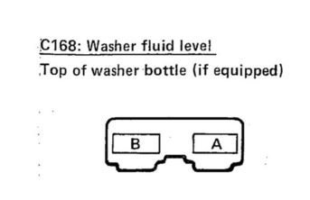
-
-
I like the idea of wrapping them with paper. Advice I can take. Thanks
-
Adding low washer fluid warning to an MJ
Ωhm replied to Anthi4078's topic in MJ Tech: Modification and Repairs
Are you guys talking about the wire from C100_H6 (IP side) and C204_15 as missing on RENIX, but present on HO?