


Ωhm
-
Posts
3166 -
Joined
-
Last visited
-
Days Won
6
Content Type
Profiles
Forums
Gallery
Everything posted by Ωhm
-
MJ_1987_Electrical_Manual_1.pdf
-
-

1989 new owner, have a question on ignition wiring
Ωhm replied to superjay5ive's topic in MJ Tech: Modification and Repairs
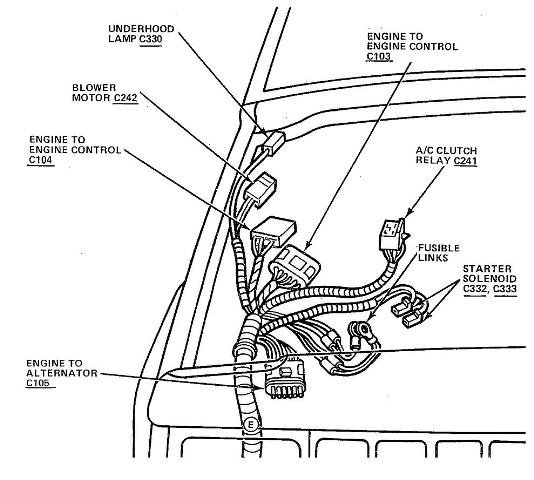
Two (2) moves here: 1) Disconnect C103. On the Engine Harness side, look for 12vdc on pin C103_E (YEL). Turn KEY ON for measurement. or Back track wire at D2_4 to Engine Control Harness Splice_F (YEL). Circle with the (F) in it. I suspect NO VOLTAGE from IGN SW (C103_E) at KEY ON or faulty Splice_F.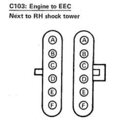
view.jpg.05dbe83ae9ffca47e7e028f11a31dfd4.jpg)
-
1989 new owner, have a question on ignition wiring
Ωhm replied to superjay5ive's topic in MJ Tech: Modification and Repairs
RED wire seems to be an add-on wire, not factory. RED is usually HOT AT ALL TIMES. With RED wire disconnected take the following readings: Using a voltmeter or 12vdc testlight (preferred) check for Battery_Voltage_(B+) on the following pins (use battery_negative terminal for ground): D1_5: B+ (Hot at all times) D1_6: At KEY ON only (B+ (Hot for 2-3 seconds)). D2_4: B+ (Hot during KEY ON and Hot during CRANK).
-
1989 new owner, have a question on ignition wiring
Ωhm replied to superjay5ive's topic in MJ Tech: Modification and Repairs
Sure that RED wire isn't HOT ALL THE TIME, including KEY ON? -
Fuel pressure at idle should be ≈31psi. When Fuel Pressure Regulator (FPR) vacuum hose is disconnected and plugged, pressure will climb to ≈39psi at idle. Both readings are normal. Check distributor for indexing (crossfire).
-
True, good idea. Easier.
-
Truly, the only way to tell is disconnect the vacuum hose and connect a vacuum hand pump. See if it holds vacuum.
-
Yes
-
can't find the high side A/C service port
Ωhm replied to Dale Colton's topic in MJ Tech: Modification and Repairs
From the Motor Manual Guy: Air conditioning system The air conditioning system consists of a condenser mounted in front of the radiator, an evaporator mounted adjacent to the heater core, a compressor mounted on the engine, a receiver-drier which contains a high pressure relief valve and the plumbing connecting all of the above components. -
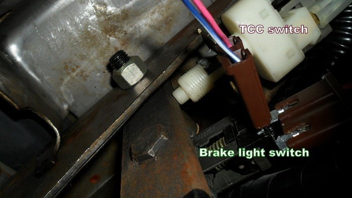
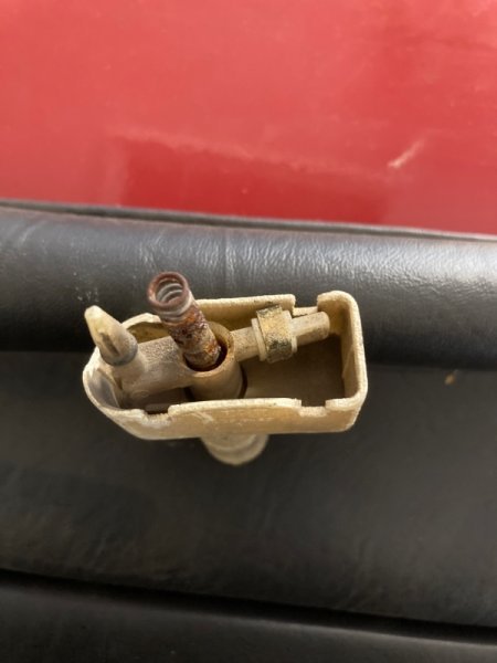
Make sure TCC/CC SW is adjusted properly. Button needs to be pushed in, in order to seal vacuum.
-
Help with Fueling issue after sitting
Ωhm replied to RustyRodder's topic in MJ Tech: Modification and Repairs
-
Power Locks, Lock works, unlock doesn't
Ωhm replied to Warren99's topic in MJ Tech: Modification and Repairs
Rear pages of the 88 shows switch testing, power door locks are one of them. AV/EV seems to be a problem child in the callouts. -
Power Locks, Lock works, unlock doesn't
Ωhm replied to Warren99's topic in MJ Tech: Modification and Repairs
Taken from the 88ElectricalManual: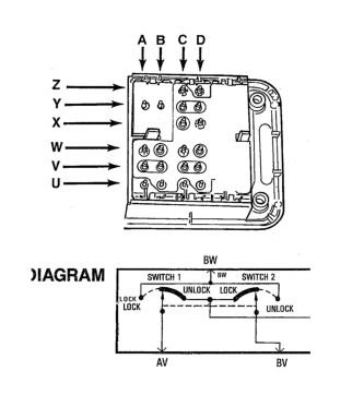
-
Fuel Pump works but no Power!
Ωhm replied to Rhys Chalmers's topic in MJ Tech: Modification and Repairs
This could be telling us something. But not yet. Now, easy for me to say, reconnect C157, then disconnect C139 at the Fuel Pump. Perform the same test on C139_C (ORN) (vehicle side of the harness).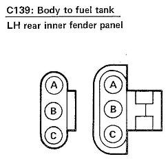
-
Fuel Pump works but no Power!
Ωhm replied to Rhys Chalmers's topic in MJ Tech: Modification and Repairs
That is correct. With voltmeter connected, turn KEY ON, NO CRANK does your voltage reading timeout after 2-3 seconds? -
Fuel Pump works but no Power!
Ωhm replied to Rhys Chalmers's topic in MJ Tech: Modification and Repairs
Under the dash, near the Parking Brake, locate connector C157. While CRANKING vehicle over, check for voltage on pin C157_F (ORN) (IP Harness side).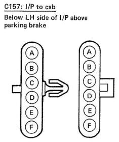
-
Fuel Pump works but no Power!
Ωhm replied to Rhys Chalmers's topic in MJ Tech: Modification and Repairs
Early 4.0L came with no Fuel Pump Ballast Resistor. -
Canadian daytime running lights questions
Ωhm replied to GirsMJ86's topic in MJ Tech: Modification and Repairs
My thought was using the Fuel Pump B+ to the NC contact and running that to the Low Beams. You could also add the Parking Lamps to this. Now, anytime the Headlight SW is turn ON this would activate the Relay and everything goes back to normal. True, none of the features available with the DRL module. GM used that set up for running a pair of Cooling Fans. Low Speed in series (6vdc on both fans), High Speed in parallel (12vdc on both fans). -
Fuel Pump works but no Power!
Ωhm replied to Rhys Chalmers's topic in MJ Tech: Modification and Repairs
Good readings. Fusible link seems good. If your equipped with a Fuel Pump Ballast Resistor, bypass it (use a jumper wire). Try starting vehicle again.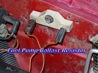
-
Canadian daytime running lights questions
Ωhm replied to GirsMJ86's topic in MJ Tech: Modification and Repairs
Okay, understood. -
Canadian daytime running lights questions
Ωhm replied to GirsMJ86's topic in MJ Tech: Modification and Repairs
You piqued my curiosity when you mentioned DRL using just a relay. Interested in looking at something. Needs proofing, untested. -
Fuel Pump works but no Power!
Ωhm replied to Rhys Chalmers's topic in MJ Tech: Modification and Repairs
Using a voltmeter or 12vdc testlight (preferred) check for Battery_Voltage_(B+) on the following pins (use battery_negative terminal for ground): D1_5: B+ (Hot at all times) D1_6: At KEY ON only (B+ (Hot for 2-3 seconds)). D2_4: B+ (Hot during KEY ON and Hot during CRANK).
-
Fuel Pump works but no Power!
Ωhm replied to Rhys Chalmers's topic in MJ Tech: Modification and Repairs
YR? ENG? TRANS? -
Canadian daytime running lights questions
Ωhm replied to GirsMJ86's topic in MJ Tech: Modification and Repairs
Is this the vehicle your looking to install DRL on?