


Minuit
-
Posts
5139 -
Joined
-
Last visited
-
Days Won
13
Content Type
Profiles
Forums
Gallery
Everything posted by Minuit
-
https://www.ebay.com/itm/Snap-On-JEEP-1-Adapter-for-MT2500-Scan-Tool-P-N-MT2500-49-FREE-SHIPPING/143671225011?epid=1718881744&hash=item217378eab3:g:F38AAOSwgs1fJdbM Unless you have a 91 or 92; that one's CHRY-1 for the engine and CHRY-2 for the transmission (if auto)
-
 It would appear that our brave leader Pete M will be testing the prototype. It will be in his hands by the end of the month, and will hopefully provide smooth, painless service. If circumstances allow, the possibility of making at least one more prototype is on the table. Transparency Report: 6 August 2020 Number of people on waiting list: 93, including 5 new additions in the past two weeks. Currently in contact with the top 15 customers on the list. Two orders are actively being worked on, with another two projected to be actively worked on by the end of the week. The lab is now in what I would call a fully operational state. While there is still some tweaking to do with my test equipment and the general layout of the working area, I am now confident in being able to sustain a reasonable level of productivity. In downtime between orders or while waiting for parts, I've been working on some very interesting prototypes. It's too early to spoil many details, but I can say that in the very near future, circuit boards bearing the Jeremy's Radio Emporium name and logo will be hiding inside of factory Jeep and AMC radios. The first of these prototypes will be making its way to testers within the next couple of weeks, with more to come very shortly after. The first project to be released will be the most technologically advanced auxiliary input ever to be offered for a vintage car radio, with the much awaited 6-channel RCA output preamplifier following soon behind.
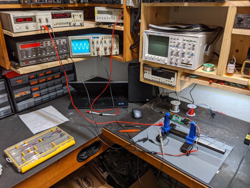
-
clean '92... white 4.0 auto 4wd... $15k
Minuit replied to Pete M's topic in Craigslist/eBay... i.e. Not Your Stuff
High output, Comanche badges in what appears to be the right place, year-correct (and probably original) radio, no signs of rust, painfully 90s stripe job, no signs of any previous owner butchery. Yep, seems OK to me. -
Here's the thread about the 2019 show: I drove my '91 1500 miles to be there. If anyone has any doubts about showing up to this show when/if the pandemic dies down, JUST GO. Easily the most enjoyable Jeep related thing I've done.
-
New Pads and Rotors Binding?
Minuit replied to SoCalManche's topic in MJ Tech: Modification and Repairs
Some brake pads are loud (cheap pads are loud, and "performance" pads can be really loud), but the anti-rattle clips can cause noise if they aren't put on right. Also, check the dust shield to make sure it's not hitting the rotor. Do you have the FSM? Some varieties of this brake setup have "inside" pads and "outside" pads that are tantalizingly close to being the same, but will cause horrible brake noise if mixed up. Not sure if your truck is this way, but the '91 2WD setup is. Don Hornbrook and I both had problems with this on 2wd 91s. That's officially the most disgusting brake fluid reservoir I've seen, and I've seen some nasty ones. You did good getting that out of there. That was going to cause a lot of problems down the road, and might already have. -
-
Help urgently wanted! WHO: Someone trustworthy enough for me to loan a prototype radio to for a short to medium term real-world test. Someone who regularly drives their truck and listens to a variety of music types and volumes. Preferably, a previous customer or someone who I have had dealings with in the past. Their vehicle must have the 1988-1996 Jeep radio plug, and the electrical system must be in good condition. WHAT: Testing of a prototype fully-automatic auxiliary input system that does not require disabling of any of the radio's features to work. I have built a prototype RX-173 with this system built in, and it works extremely well on the test bench. However, I need information on real-world performance from someone trustworthy. Putting it in my own truck and driving around is not an option at this time. WHEN: Within the next two to three weeks. Testing term will be at my discretion, but plan on two weeks to a month worth of normal use. HOW: I will ship (at my expense) you an RX-173 that is functional but ugly. It contains a fully integrated prototype signal-detection and switching system that provides a fully automatic auxiliary input. The cassette deck has been removed and the cassette door will be sealed closed. None of the illumination is functional. The radio will have full AM, FM, and Auxiliary Input functionality. It will come with a bracket pre-installed, and will be ready for installation upon receipt. The tester will install the radio in their truck and use it as normal for the testing period. Upon completion of the testing period, the radio will be returned to me (at my expense). The prototype is property of Jeremy's Radio Emporium and will feature prominent tamper-evident seals. I respectfully ask that the tester does not take the prototype apart; the circuit board inside is hand-made and could potentially be fragile. In addition, the prototype does not represent the full quality, dimensions, or design of the final product - the final product will be significantly smaller, made entirely of surface-mount components, and built on a manufactured circuit board of my design. Description of prototype function At all times when the radio is powered on, the triggering system monitors the auxiliary input line for signals. When no signal is detected, the radio operates as usual, with all normal functions available. When a signal over a configurable threshold is present on the auxiliary input line, the triggering system switches to the auxiliary line via a mechanical relay. The relay is rated for a minimum of 100,000 cycles and in my testing has caused very little "popping" upon activation, but this requires further testing. After the signal on the auxiliary line has dropped below the activation threshold for 8 seconds, the radio will revert to the mode selected on the front panel. The triggering system is not active when the radio is not powered on, and will cause no drain on the vehicle's battery. As part of a self-test, the radio will switch to AUX mode for 8 seconds after being powered on. If no signal is detected on the auxiliary input during this time, the radio will revert to the mode selected on the front panel. The prototype's auxiliary input cable is identical in layout to the standard Enhanced Radio. The cable is rear-mounted and extends from the right rear of the radio chassis. Please post in this thread or send me a PM if you are interested in this test.
-
What Minuit knows about stock Jeep radios
Minuit replied to Minuit's topic in MJ Tech: DIY Projects and Write-Ups
Pretty sure that's a trimmer capacitor for the radio tuner used in the alignment process. Best not to mess with it. -
Need gauge readings to be able to tell anything.
-
Removing the carpet is pretty much a case of taking out all of the interior trim that touches it. Also, the gas pedal. Once everything that pinches it down is gone, it just lifts out. If a job's worth doing, it's worth overdoing - mass-backed carpet over mass-loaded vinyl over nonabsorbent closed cell foam over Dynamat in areas where water cannot reach. Road noise is practically extinct within the confines of this vehicle. Everything below the glass is covered in at least one layer of 1lb/sqft MLV. Fix your water leak first and THOROUGHLY pressure test the cab for any form of leakage before you even think about putting it back together. (holy $#!&, these are some staggeringly awful pictures. Next time I rip the interior out I'll get some better ones, promise)
-
Windows won't go down all the way.
Minuit replied to Muncher's topic in MJ Tech: Modification and Repairs
I think I did a separate write-up of it somewhere. I'll look for it here in a bit. The gist of it is, if the regulator skips, it's probably too late, but if it's stiff or moves slowly, cleaning and lubing the worm gear will make a world of difference. -
People go crazy for black interior parts for these trucks, especially seats - everything else can be painted. If you find the right customer, you can basically ask whatever you want and get it.
-
Fender badge in the wrong place too, but it basically goes without saying these days. How many car painters are there out there that can't read a tape measure?
-
Welp, fired neurologist #1 today after a week of not being able to get in touch. I'm now a patient of the top neurologist in town as of today. As far as condition goes, I'd say I'm about halfway to where I need to be. The partial seizures have not completely stopped but I can go multiple days between them. I've been slowly ramping up my workout regime and I can fit into size 34 pants again... feels good. Also, I made this overly complicated clicky relay thing.
-
What Minuit knows about stock Jeep radios
Minuit replied to Minuit's topic in MJ Tech: DIY Projects and Write-Ups
The speaker connector is the six-pin one. On the radio side: White: Right front + Black / white stripe: Left - (shared between front and rear) White / black stripe: Right rear + Green: Left front + Black: Right - (shared between front and rear) Green / black stripe: Left rear + Per the RX-758 service manual. -
At least you're honest about it, I guess.
-
rare old Jeep CD player for sale :) nos too!
Minuit replied to Pete M's topic in Craigslist/eBay... i.e. Not Your Stuff
The new owner of this radio has been in touch with me, and I might very well be getting elbow deep in this one too! -
What Minuit knows about stock Jeep radios
Minuit replied to Minuit's topic in MJ Tech: DIY Projects and Write-Ups
-
I've totally never, ever blown up anything by probing it wrong. Ever! This is a good chance to add a warning to what I posted above: in most cases, the outer ring of a test instrument's BNC connector (which is connected directly to the ground clip of your oscilloscope probe) is connected directly to your house's AC ground. To avoid rapid unplanned disassembly of your scope, probe, or device under test, if your device under test is connected to the AC mains of your house or building, the ground clip of the probe (or negative lead if you're using a BNC test lead adapter) MUST be connected to something grounded! For example: if you're working on another piece of test equipment that's plugged into an outlet, make for damn sure whatever you hook the ground clip to is also grounded. When you connect the ground clip on your scope probe to something, you're effectively connecting whatever you hooked the clip to to your building's ground point. Be sure that won't cause a problem. If your device is not connected to your house's AC wiring, this isn't something you have to worry about. Any good DC power supply will have a "floating" negative terminal. Anything battery powered is completely isolated from your house's wiring. There are also devices called "isolation transformers" that allow you to completely separate your device under test from your house's wiring. I'm not saying you have to use an isolated power supply to work on something, but if not, be very careful about where you hook the ground of your instrument to. If it's plugged into your house's wiring, it's basically a short to ground right at your fingertips. Here's a more detailed explanation:
-
A Quick Overview of Test Equipment Next to a multimeter, the oscilloscope is the centerpiece of almost any electronics lab. Its purpose is to visualize any electrical signal that changes with time. That can include almost anything that isn't straight DC - audio signals, crystal clocks, display driver outputs, sensors on cars, anything pulse-width modulated, etc. You'd be surprised at how many things in even an older car are not straight DC signals. For example: a common test of a Jeep CPS is to hook a meter to it and measure the AC voltage output when cranking. An oscilloscope would make for a much better test of your sensor, but most people don't have the fancy toys. Here's my portable Tektronix THS720P looking at the PWM waveform of a car blower motor - to control the speed, the car is essentially turning the motor on and off again twenty thousand times every second. It does this so it doesn't have to waste a bunch of energy with a resistor. There's about seven million ways to connect an oscilloscope to the device under test. Most test equipment uses BNC connectors, and there's a huge variety of different adapters to hook up almost any type of test lead you can think of. For an oscilloscope in a general electronics setting, the most common one is this type of probe: The alligator clip connects to ground (or whatever your device is referenced to), and once that's done the probe then works almost like a positive multimeter lead. This one works as both a hook and a probe - to use as a probe, just pull the cap off the end. The ground wire is short on purpose to limit noise - it's basically an antenna, and for delicate, very high speed signals noise has to be kept to an absolute minimum. Most oscilloscope probes are "10X" probes - that means the signal that's passed onto the scope is attenuated to 1/10th of what it actually is. That improves the performance of the probe at high frequencies. This one can be switched to "1X" mode which doesn't attenuate the signal at all. In 1X mode, it can also be used to inject signals from a signal generator into the device under test. There are a lot of fancy probes out there, but this is useful in 99% of situations. I think I paid $15 on Ebay for two of them. Here's the probe shoved into the speaker connector of a radio. The ground lead is clipped to the chassis of the radio, which would be connected to battery ground in the vehicle. Once the ground is connected, just put the probe on whatever you want to measure. It basically works just like a normal multimeter lead. For not-so-sensitive signals such as the car blower motor example, I can use a BNC adapter to connect standard multimeter leads - one to the signal, and one to ground, just like a normal multimeter. You'll lose bandwidth and pick up a lot of noise, but for cars this really doesn't matter. You can also connect test equipment together using plain BNC coax cable. Oscilloscopes have a lot of controls, but almost all of them have a handful of controls that really, really matter: Graticule Controls - the grid overlaid on an oscilloscope display is called the graticule. It's split up into "divisions" in both directions. The distance between a pair of lines in the same direction is one division. The vertical scale is voltage, and the horizontal scale is time. How much voltage or time each division represents is adjustable. Volts/DIV: The vertical scale of the scope. This controls how much voltage is represented by one vertical division on the graticule. Vertical Position: Moves the waveform up and down on the screen. Useful when looking at two or more separate waveforms at a time Sec/DIV: The horizontal scale of the scope. This controls how many seconds (more often: how many tiny fractions of a second) are represented by one horizontal division. Horizontal Position: Allows you to shift the waveform back and forth. Coupling: Typical options are AC, DC, and Ground. AC coupling shows you only the AC component of a wave. DC coupling shows you the AC portion, plus any DC bias that may be present. Ground coupling shows a flat line on the screen, allowing you to set the "zero" point how you want it. Here's a 1 kHz triangle wave in AC coupled mode on the Tektronix 2236. Counting from a top peak to the bottom peak, we see that this wave takes up 4 vertical divisions. I'm set to 0.1 volts per division, so that means this wave has an amplitude of 0.4 volts peak-to-peak. Now, let's switch to DC coupled mode and see what we see. I haven't touched any of the controls other than the coupling, but we can see that the wave moved to the top half of the screen. All we could see in AC coupled mode was the part of the waveform that changes with time, but now we've exposed the DC bias of the wave. As it turns out, this waveform goes from 0 volts (middle of vertical scale) to 0.4V (very top of screen) - the amplitude is still the same, but the "middle" is in a different spot. Knowing whether or not something has a DC bias can be VERY important when testing. In this pic, we can also see the special feature of the Tektronix 2236 - the blue display to the right of the screen. It's in "frequency" mode now, showing 1.00031 kilohertz. There are actually more digits than that on the display, but the camera shutter missed them. That display can either be connected to the scope's input or to an integrated multimeter. That feature cost the original buyer of this scope a thousand 1984 dollars by itself. All of that's fine if you're only looking at a wave that repeats itself over and over again without any hiccups. The Tektronix 2236 is an analog oscilloscope dating back to 1984. The major limitation of an analog oscilloscope is a big one: it can only show you what is happening right now. Here's an attempt to "zoom out" on an audio signal on the Tektronix: That is completely useless - the CRT on the scope can only draw what is happening right now. The display has faded before the CRT even gets to the other end of the screen. This scope has absolutely no storage or memory function. That can be very inconvenient - for instance, if I'm looking for an intermittent fault in a radio. I need to be able to see what's happening on the scope even if I'm not looking at the scope at the exact moment the problem happens. This scope cannot do that in any way. That's not to say that an old oscilloscope isn't a useful instrument, but they have some serious limitations. I said earlier that the full width of an oscilloscope display normally represents a tiny fraction of a second. Here's 5 full seconds of an audio signal on a HP 54645D digital storage oscilloscope. This thing cost an eye watering amount of money in 1997 (I can't remember where I saw it, but think in the ballpark of $15,000 back in 1997) for good reason - it can take up to 200,000,000 samples of a waveform every second. That waveform can be stopped at any time, and anything unusual can be zoomed in on and investigated in detail for as long as you want. It can also display all kinds of measurements right on the screen, add, subtract, multiply, divide, and analyze the frequency components of waveforms in real time, and save up to 100 of them for future reference. That 5 second waveform? I can zoom in on any part of that. I can also save it for later. Even though it's 23 years old, this is still a very potent and useful piece of equipment. It holds its own against new models to this very day. You can also play games on it. Here's the same triangle wave demonstration on it: Other than the huge amount of extra functions, the connections and probes work exactly the same. You might think old digital technology would mean it's slow and clunky, but this thing is very quick and responsive. In school, I briefly used some far newer Tektronix gear and it was nowhere near as responsive and fast as this HP. Anyway, enough showing off. More test gear. This rather grungy looking machine is a frequency counter. You put an AC signal into it and it tells you the frequency, or you can do some fancy math and other stuff with it. The main thing I use it for is aligning tape decks, and that's what it's showing in this pic. Typical practice is to play a test tape with a 3000 Hz tone and set the deck for 3060 plus or minus 40. I'm 8.498 hertz high here. That's well within allowable tolerance. One of these days, I'll clean this thing up a little bit. It follows the same rules as everything else does with BNC connections. I've actually got an oscilloscope probe connected to it here, but any combination of BNC adapters and test leads will work fine with it too. Just out of frame to the right is a bench DC power supply. Not much to say about it, really. It supplies power, as long as you don't need more than 20V or more than 3 amps. The absolute behemoth on the bottom is a function generator. Its primary purpose is injecting a test signal into whatever is being tested. This is useful for all kinds of things - testing frequency response of speaker crossovers, checking amplifier gain, making sure a radio has input on all channels, performing power tests of radios, standing in for a music signal when testing auxiliary inputs, etc. Here, I have the function generator hooked up to the frequency counter to check that the display on the function generator is correct. This particular model dates back to 1986 and has a ton of features not normally found in a machine of this age - full digital control, battery-backed presets, frequency sweep, a number pad to input specific settings, etc. I'll often use an oscilloscope probe with it to check for audio output on all channels of a radio, for instance. I'm somewhat on the fence about keeping this particular unit, just because it's so damn big. Here's a specialty item: an "L-C-R" meter. "What the hell is an LCR meter?" I hear you ask - It tests inductors (coils/chokes), capacitors, and resistors. I work with old electronics all the time, so you might think I'm running into bad capacitors every day. Not really. You know how many radio issues I've run into that were absolutely, certainly, without a doubt caused by bad capacitors? 0. Good quality capacitors last a really long time. I just changed a bunch of 36 year old capacitors in the Tektronix 2236 and most of them were pretty darn close to how they should be. I just bought this thing, and I only bought it because I thought it looked cool and it was really cheap. This one dates back to the 1970s, and while it's somewhat limited in capability it's still very effective and much more accurate than cheap capacitor testers you can get online. But really, you won't need one of these unless you take electronics very seriously. Unless you work in a serious lab, you probably won't ever see one of these. It uses banana jacks and connects to capacitors with any standard test leads, but ones with alligator clips are recommended. For testing polarized capacitors, make sure the "H" terminal is on the positive side of the capacitor to avoid unwanted explosions. One thing that I want to make clear: equipment like this is not out of reach of normal people, nor is it required to play around with electronic circuits. When it was new, you're probably looking at $50k or so of equipment on my test bench adjusted for inflation. I've spent a tiny fraction of that on it. Almost all of it was high end lab-grade stuff because playing around with vintage high end test gear is fun for me. You might notice a lot of old HP stuff - they're built like tanks and are often still in calibration after 30 years. You can pick up a working oscilloscope online for less than a hundred bucks. Ditto for a power supply and function generator (if you even need one). You probably don't need a frequency counter, and if you do need one you'll know it. If you have a college with an electronics program nearby, they auction off test gear all the time. If you live in Mississippi, here's a lot 8 oscilloscopes going for $17 as of this writing. Here's three going for $25. You can use any handheld multimeter for electronics. If you have an old Jeep you should have one anyway! For the first few months of my radio business, I used a tool battery for 12V and an old handheld multimeter. That's it. I had been in business for 6 months before I bought the Tektronix 2236 scope I was showing off. My electronics hobby has paid for itself many times over.
-
What Minuit knows about stock Jeep radios
Minuit replied to Minuit's topic in MJ Tech: DIY Projects and Write-Ups
The designation pretty much just means what bracket it came with from the factory. You'll see XJ, YJ, SJ, and XR variations most often. There is no difference in the radio itself in almost every case. Even when there's a difference, it's usually very minor internal differences. For all intents and purposes, the 1988-1996 Jeep radios are interchangeable. It's worth what you can get someone to pay for it. The AR-7752 is a common model and has no special features that make it stand out. Condition is everything. Don't expect to retire off it, though. -
anyone polished up their gauge cluster plastic?
Minuit replied to Pete M's topic in MJ Tech: Modification and Repairs
With the right techniques and products you can polish anything. I got lucky on the cluster I got for my '91 all those years ago. It actually looked acceptable as-is. The one in my 'bird and the blue cluster for my '89 are pretty nasty though. -
I *might* be able to come up with something in this category Playing around with the test gear is my favorite part of the whole thing. All of it top of the line in its day, most of it bought either broken or half-broken for stupid cheap on eBay. The big function generator on the very bottom left was last calibrated a few days before my truck was built in 1991, let the smoke out twice within 30 minutes of me first plugging it in, and it's still in calibration even after replacing every single tantalum capacitor in the entire machine. I just finished getting the Tektronix 2236 oscilloscope next to it back in working order. That's the first piece of test gear I ever bought for my business, and even though I have a much more modern scope right next to it, it's still my favorite piece of equipment to use. It has a pretty slick multimeter display built in that can be coupled to either the main input of the scope or to a pair of test leads that attach to the side. So it's an oscilloscope, frequency meter/timer, thermometer, and multimeter all in one. Pretty slick for 1984. Built like an absolute tank, too. (the oscilloscope displays give off enough light to be able to see what I'm doing even with all the lights off, by the way)
-
As some may notice, I have a slight interest in electronics. I'm sure I'm not the only one here who does. Some examples for possible subjects would be debunking myths, testing procedures for various things, repairs and restorations of equipment, possibly some test gear reviews, and more. Anything that has a relevance to general electronics or automotive electronics would be fair game. If this is something that at least a few people would get enough enjoyment or learning out of to justify the time investment, I'd be more than willing to start up an electronics thread.
-
One and a collection of parts that mostly adds up to make up another.