


llhat
-
Posts
219 -
Joined
-
Last visited
Content Type
Profiles
Forums
Gallery
Everything posted by llhat
-
~440 Hertz road noise goes away on veer left
llhat replied to AnotherOldJeepGuy's topic in MJ Tech: Modification and Repairs
i'd give a big thumbs UP and proceed as normal!!! U get the seal out?? -
thanks for this, soon to replace tires on stock height 1989, when i obtained it @ 72k, it had 235 BFG all terrian C loads on an aftermarket 'centerline' looking wheel, @ 140k replaced with take-offs 30 x9.5 GSA goodyears with a 'accessory' jeep wheel polished, but seemed to have deeper backspacing than those others on the back i would hear a 'click click' st times from a rub on emergency brake cable, and on front lower control arms at times. originally had steel wheels. Now debating on dropping back to LT235 or staying around the 30 x 9.5 (my 'tire guy' has some mud terrrains he took off of his scout... will decide next week.) it now wants to drop out of OD 'quickly' at speed (3.54 gears)... but pre 2000 when driving it a LOT it would get up to 23mpg.
-
~440 Hertz road noise goes away on veer left
llhat replied to AnotherOldJeepGuy's topic in MJ Tech: Modification and Repairs
on most of the stuff i worked on in the past, took a drift and from the outside of the hub, put the drift on the inner bearing and gave it a whack or two the seal and bearing should drop out... If you want to pry, do it at "A" , B is the seal lip, it's gonna be trash anyway and if I 'know' i have the replacement I'll go in the opening with a seal removal tool and pry er out, even a big screwdriver will work as a lever the threads... hmm, yea a die may work, but you could also take a triangular 'swiss' file and restore the 'vee'... but the outer diameter of the thread has already suffered. this bearing nut is not torqued to an extreme amount, and the cotter pin will keep if from loosening from rotation, but there is the risk of the nut letting go linearly and no longer retain the hub... sort of depends on how the nut interacts with the root of the thread on the spindle. how much risk... I won't say.... but them are some boogered threads. -
~440 Hertz road noise goes away on veer left
llhat replied to AnotherOldJeepGuy's topic in MJ Tech: Modification and Repairs
oops, thought he was measuring pads... rotor lip bit more difficult... but a regular anvil micrometer will bridge the lip... but if no divider style measuring caliper, then probably no micrometer either. the jaws on the vernier may be relieved near the beam.. that may bridge the ridge -
~440 Hertz road noise goes away on veer left
llhat replied to AnotherOldJeepGuy's topic in MJ Tech: Modification and Repairs
guess talking about an outer 'lip' on the edge of the pad.... in a small section take a file and knock the lip off then your measuring caliper's flat surface can access the flat part of the pad. -
~440 Hertz road noise goes away on veer left
llhat replied to AnotherOldJeepGuy's topic in MJ Tech: Modification and Repairs
noted the comment on bearings seizing on the spindle.... seeing in your sig yours is 2wd, so there is a conventional spindle (IIRC) and not a bearing pack. so you could pull the hub and check the bearings by removal of caliper and the castle nut under the spindle cap. the 4wd are a press fit bearing pack and most do not have the press or adapters for the press to remove the bearings without damage to them. 'simpler' to replace the bearing pack in most cases. these are usually sealed bearings. on 2wd should be 'regular' tapered roller bearings and their matching cup, look for 'fretting' of the rollers and in the surface of the cup. bearings probably not too expensive but try to look for top shelf quality bearings and get the seals while at FLAPs, as well as good bearing grease. good luck. -
ok, another thought, I believe the is a 'tip' on upgrading the ground wire on the TPS wire bundle.... maybe search will find it. otherwise ground you multimeter negative, then probe ( from memory "A" wire on connector for the voltage with your multimeter positive, I'd think if you get the reference voltage, then the ground circuit in that bundle could be the issue. at one point I believe the 88 electrical manual was posted here as a PDF file, you may can find the pin out for first, the supply wire on the C101 connector (that 'may' be the source of issue during that procedure) then trace back to the ECU connector. I am unsure just who posted that link to the manual, but 1988 was last year for C101 connector.
-
? did it run after the c101 delete? How well or how bad? one would think with that low voltage, the ecu would not 'respond'.... Possibly a bad back probe connection... I ran into this with testing the transmission solenoids for resistance at the connector... You're probably going to need the complete wiring data to trace to the pin-out on the ECU connector or re-test at the TPS connector by back probing ...with the connector still connected to CPS...
-
yeah, i had to "buck it up" too but it sure is nice not manually shifting this auto transmission.... not sure what cost would be for a bench technician to test the TCU board components, some report age on solder joints is an issue, as well as failed transistor/resistors or other board level components. the speed sensor is also a 'testable' part...
-
think that may be the key there... though some of the tests we ran on wiring helped narrow it down I did have a problem with NSS, but replacement only got me back up lights in reverse there's some TCU on evay, but many are not sure "IF" they work... I got lucky on one source there. If you find a good source, share "after" you are pleased. it may not be a bad idea to have a spare there's a thread here about one fellow that found a bad resistor in his TCU and replaced it.
-
Sorta on the subject.. for the female side of the belt, who offers the sleeve that stiffens this side? is there a better alternative? (gray color)
-
with the fuse pulled you 'should' have been able to manually shift the transmission to 1, then move toward D (it skips 2nd and goes to 3rd) you will not have overdrive or TC lockup... I drove mine around for a good while manually shifting [it would try to start off in 3rd gear, then would 'go' when i moved the lever to 1] According to a recent thread just down the way, read it even though the title of the thread seems not related... The TPS may be a decent trial, but you 'can' test the output ( I think analog meter is preferred to see sweep and any dropoffs) otherwise look at an older thread i started..(it is about 7 pages back !) it had a LOT of tips from Ohm and tests to wiring.... Ultimately 'my' issue was the TCU, but there were a LOT of red herrings along the way... including the NSS... I do wish for you expedient repairs!
-
sounds like really good news. the shifting issue being fixed was an added benefit, but the inputs from the TPS are also 'part of the plan' for the TCU, mine was not as simple. good luck with the rest and enjoy the drive..
-
yes, charcoal canister for evap system... at some point in running cycle, there will be a vacuum signal to purge the vapors, believe controlled by a solenoid on the drivers side fender... not sure where a vacuum diagram is posted . I'd either cap them off or (preferred) fix them. one of course goes to top of fuel tank, there's probably two fittings on top of tank "Y"d together for trip to canister. yep, not having the map sensor detecting vacuum will do some funky things... sill have marginal concerns with liquid oil from exhaust... sure not condensation with carbon/oil mix ?
-
liquid oil or blue oil smoke? valid thought on getting those vacuum leaks stopped. this sounds like a long path, but navigable
-
heck i HAD to look it up... Load Sensing Valve thanks for the tips, I have not deleted, nor do i think i have issues with mine.... yet
-
Thank you for the link, yes that is the article March 1989 Hot Rod magazine... It is on page nine as indicated, scroll down the page to post by fiatslug87 I have retained to computer so i can enlarge the image to read again... this was about 8 years before i bought my 1989 MJ with 70k on it.
-
way back when I recall reading an article in Hot Rod Magazine where they built a stroker engine and installed a paxton blower this was probably in the 1989 time frame. anyone know the article?
-
Quick Wiring Harness Routing Question
llhat replied to Gojira94's topic in MJ Tech: Modification and Repairs
dunno for sure, but be sure to protect those wire in the lower image (driver's side?) not going to be near mine soon to try to look to see what factory did would make sense to not have them routed through the brace as harness would need to be 'un threaded' if you removed the brace. -
would that not show some weird readings when testing the TPS signal? Base voltage, regulated voltage, and if using analog, noting the 'sweep' of voltage? No change in TPS signal would seemingly confuse the hell out of the ECM and TCU.... glad you are whittling this down....
-
and one has to be concerned with the effect of heat and oil on the material... yeah there's room for tolerances.... wanted to give a starting point on a new, unused gasket.
-
i have not checked fitment on the new Stant Cap as of 'now' , it also was not installed on the new cap, but in the box. I do not know how the washer measurement compares to the NAPA part number. I've an 'old time' hardware store here, have not checked it for similar washer.
-
unknown, but.... Here's measurements from a NEW Stant part# 10085 unit OD 1.77" 45.2mm ID 1.05" 26.6mm THK 0.09" 2.4mm (taken with harbor freight digital caliper)
-
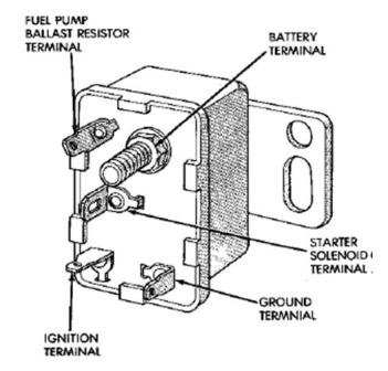
How about your fuel pump resistor, is it bypassed? When the start solenoid is engaged (behind battery under the plastic electrical cover (beside the coil), there is current directly placed to the fuel pump, bypassing the resistor on the drivers side fender (beside air box). its terminal is at the top of the start relay, you can power the pump from that wire by unplugging it and applying +12v to the wire.
-
in your prior post you showed a pic of the IAC pintle with the buildup of 'stuff' on it... you did not though IIRC state cleaning of the orifice in the throttle body, so yes, this could be at least another trial...