Gojira94
-
Posts
718 -
Joined
-
Last visited
Content Type
Profiles
Forums
Gallery
Everything posted by Gojira94
-

Help me identify shocks, rear leafs
Gojira94 replied to Gojira94's topic in MJ Tech: Modification and Repairs
I believe you're right. Looking into it, it seems that Skyjacker and Rusty's have the same manufacturer for some of their more budget shock options. Skyjacker Nitro and Hydro series have the same style 3 stamped lines at the bottom of the tube as mine in the pics above, though you can't make out the details of what they say in the website pics. Rusty's calls their front shock by model number RX-27, for either 2" or 3" lifted MJ. They call for RX-13 on the back for for more than 2", less than 4.5" lifted. The RX-26 is what Rusty's sells for XJ rear with 3" lift. Not sure what the difference is between the RX-13 and RX-26, though it may have to do with the rear lower shock mount location being slightly different height between MJ and XJ? IDK, not that familiar with the XJ rear axle. -
You can get assortments of rubber grommets, vinyl caps, etc. at some parts stores but they're usually limited stock or special order. In my area, it's NAPA, O'Reilly, Advance and AutoZone. I've seen 170-180 piece grommet and cap kits on Amazon for $12-$20. When I'm finishing up my project I'm going to need a few various/ sundry of these and will probably order one of each, caps and grommets. For your antenna wire pass-through I'd get a solid rubber grommet, punch the wire through it, get it properly situated and then smear a little RTV around the wire on both sides. That ought to last for 10+ years.
-
I mocked up the bar and brackets using 8 1/4” XJ/MJ links to get an idea of where I’d land with length requirement on the end links. There are TJ links just like the ZJ ones but an inch longer (9 1/4” vs 8 1/4”). I have a pair of Moog 8 1/4” ZJ links on the way. With the driveline out, I think it looks like I’m right where I’ll want to be once it’s back in and drops the body a couple of inches.
-
True- I wish there was a great cache of every fastener we ever wanted for everything. This MJ was spared a lot of that kind of moisture-retaining dirt, probably because it’s been 2WD all its life, not really a suitable off-roader. I’m now at the age where I get mail inviting me to join AARP (not so fast I’m not the double five yet), and this is my first 4WD and first Jeep (I’ve been high performance street/ track all my life). I intend to get my MJ dirty but never leave it that way. Keeping things clean and in good order after the fun is had, is my way.
-
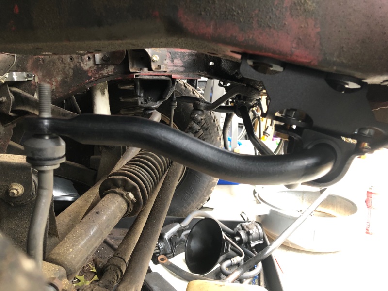
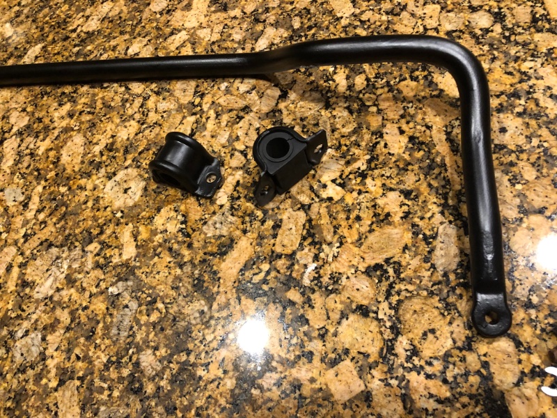
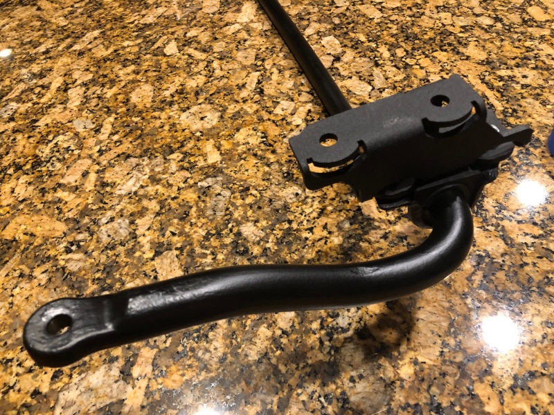
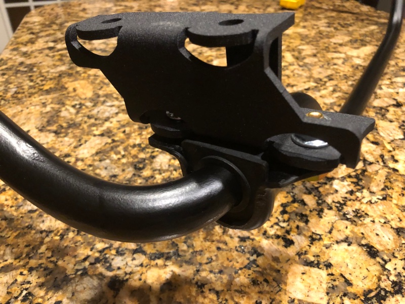
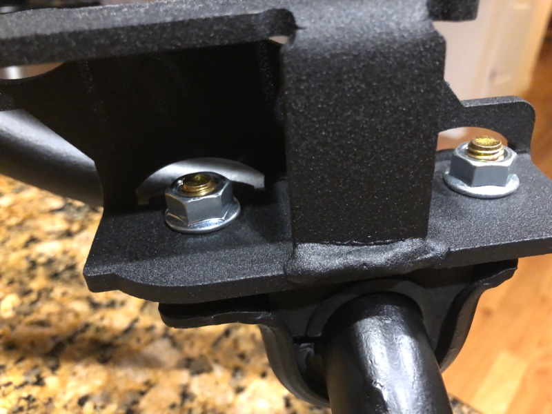
Grabbed a 98 ZJ 5.2 front sway bar and brackets today. Had to go to a yard almost an hour away on a gamble it (the bar) would still be there. I was sure I’d score a 28mm bar since the VIN lookup on it said it had the “SDU: Heavy Duty Suspension…” package. It’s way beefier than my stock 24mm but I was disappointed when I mic’d it at only 26mm. Now I have to decide whether to do adjustable links or go with ZJ links with the stem/ ball swivel arrangement. I cleaned it up and painted it and got a new pair of 26mm bushings for it. Mocked up with the drop brackets:
-
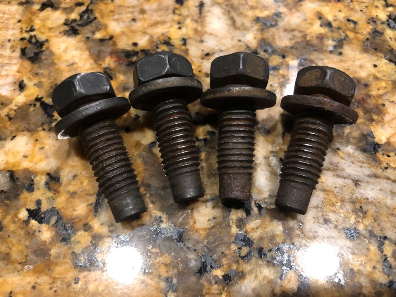
What, these? I’m lucky this MJ has been in NC all its life. My only real rust is the floors from incoming water, the battery tray support and the famous clutch master leak.
-
I got what I saw were the longer links (8 1/4 vs 7 1/4) and then discovered the ones on it now are the same length, and bent from the force/ poor fitment. That (and the $45 price tag) made me pull the trigger on the IronMan4x4Fab drop brackets. I wasn't interested in $150 adjustable quick disconnects for this relatively modest build. Now I'm in the market for adjustable front arms. Some say just do the lower arms but I want uppers as well. Just doing the lowers will put the front pinion angle even more positive than it will/ should be with the D30 under it. If I've got the thinking wrong on that, I'm open to correction.
-
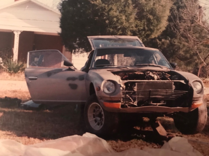
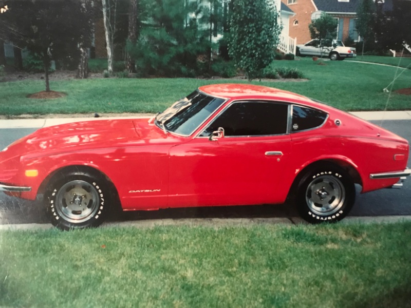
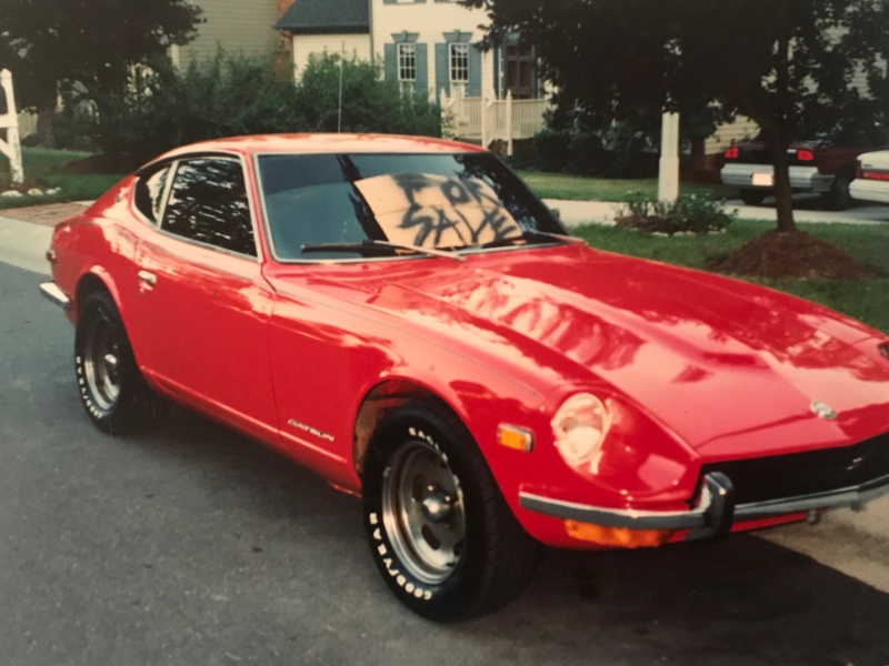
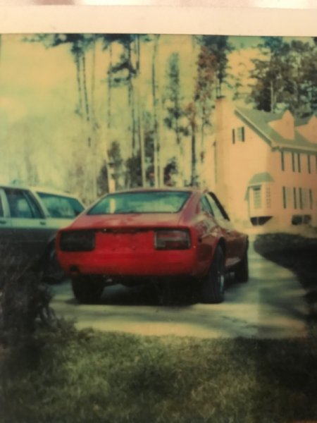
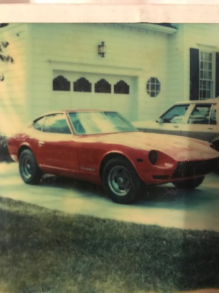
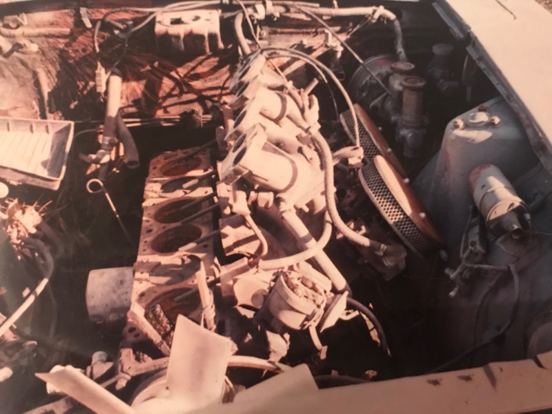
More pics Matt sent me a while back… forgot I had them.
-
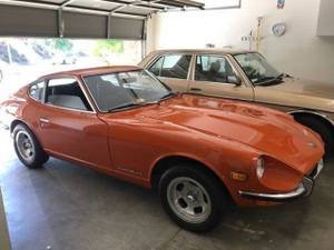
Please. I'd love to see that car. Back in the early 90s I helped a buddy fully restore a '71 240z. He sold it afterward for 15k, 1993 price. He managed to get in touch with some old Datsun gearheads at Nissan in Japan that spoke English and explained what he was doing. They sent him a full set of NOS body badges. At the end, the head had been extensively worked, outfitted with huge valves, triple 2-barrel side draft (Mikuni or Weber, can't remember) carbs, a cam from Schneider (don't recall specs at all) and full exhaust system by Ansa. Engine dynoed 304HP flywheel. Interior was showroom quality. Hidden reliability upgrades to (especially interior) wiring. I've seen this pic used on Craigslist for 'WTB Datsun 240' ads and I think it's the actual car in the image. I rode with him before the interior was in it, sat on a toolbox on the passenger side. That thing was so fast and squirrely I thought I was going to die lol.
-
Intermediate Steering Shaft blues...
Gojira94 replied to Gojira94's topic in MJ Tech: Modification and Repairs
Thanks for the feedback, much appreciated. I was kind of looking at doing the 2 spoke wire setup if possible with the 3 spoke. I have a 92 C1500 with the wire setup I can look to for reference. Same truck got an XJ steering shaft upgrade a couple years ago, I wonder how it's clocked? I want to say that shaft came from a Renix XJ. I remember that XJ was nice and a real shame it wound up in the boneyard. -
Intermediate Steering Shaft blues...
Gojira94 replied to Gojira94's topic in MJ Tech: Modification and Repairs
Oh jeez, that's right, thanks. The horn contact ring locates with 2 cancelling cam nubs in the 10:00 area of the turn signal assembly and the lock plate is indexed one way. So the contact pin stem would need to need to move 8* counter-clockwise (nope) or the contact pin hole in the steering wheel would have to be elongated (absolute LAST resort). Or... break off the stem on the contact ring, attach a wire and move the application of the ground the floating pin provides through the wheel and upper steering shaft somewhere further up behind the horn pad. FML this is insane. Is this whole special steering parts arrangement clusterf__k just a big middle finger to non-tilt owners or what? -
Intermediate Steering Shaft blues...
Gojira94 replied to Gojira94's topic in MJ Tech: Modification and Repairs
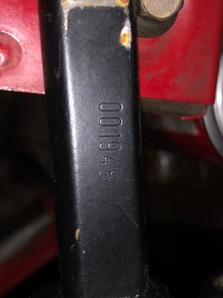
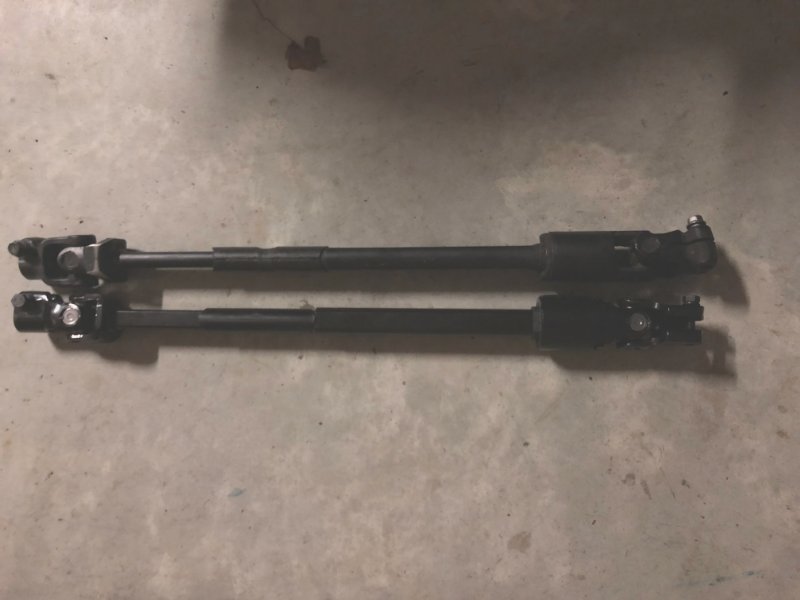
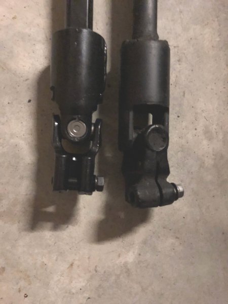
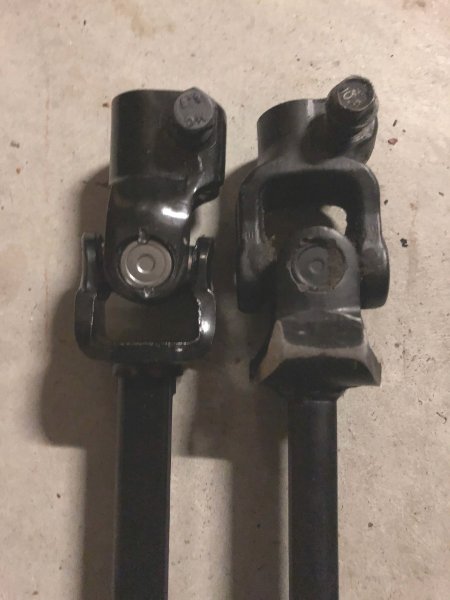
Good news about using the new shaft, whatever else is there. The steering wheel end of the upper shaft isn't indexed. I would have been willing to grind a little V there to get rid of it lol. That would have been the simple fix. Turns out I can just rotate the upper shaft, reinstall the steering wheel and go on with life. Here's what's going on: The shaft I have is a 52001948. It's quite different from the 1947. This one says 10 87, though my ride was built in March of 87. So whoever installed this shaft likely just slapped it in, noticed the steering wheel was crooked and re-positioned it. Here they are, side by side, Crown 4713943 bottom/ right, 52001948 top/ left: Side by side- notice the double-D portion of the shaft is 90* different: Steering shaft end: Steering gear input shaft end: Crown states its shaft is 570mm long measured between the centers of the bolt holes but measure it closer to 560mm (which doesn't present any problems). The 52001948 does measure exactly 570mm between bolt hole centers. I'm going to conclude that my column is original, the upper shaft is a factory 38532100 unit, and the steering wheel and lower shaft were swapped out (I know the steering wheel is not original).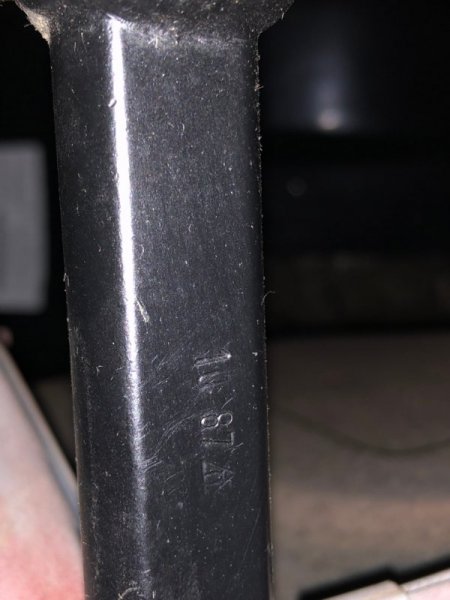
-
87 MJ Base, originally 2WD 2.5l 4-speed, no tilt, with power steering. 1987 Parts manuals show same 2 shaft options 52001947, w/out power steering; 52001948 w/power steering for a 4.0 5-speed, so power steering seems to be the differentiator between the 2. The 1947 and 1948 are 570mm. Upper steering shaft for non-tilt columns shows 83502100 for any/ all 1987 applications, power steering or no. At least for 1987. 1986 goes down a deep rabbit hole of shaft combos. I received a new Crown 4713943 intermediate steering shaft today. This part cross-references with OE part (don’t know- at first thought 52001947). The flat spots on the double-D end and splined end are (almost) perfectly 90* offset from each other. The old one has them maybe 80-82* offset. Uh-oh. The flat index spot on the steering box input shaft is at 12:00, Pittman arm is perfectly straight, wheels are straight, steering wheel is straight but I don't recall if the splined steering wheel end is indexed on the upper steering shaft. Steering wheel, upper shaft and lower shaft all agree and mate to the steering box with what's there now. However, any or all of these 3 may have come from almost any other MJ/ XJ from 86-94. The column housing even may have come from something else. I suppose I may have a set of some 1986 parts (2 different parts 570mm bolt hole center to center, 580mm bolt hole center to center, each, for w/ PS and w/o PS, for a total of FOUR lower shaft options for '86). The 83502100 upper shaft matches the 570mm lower shaft, 82600223 upper fitting the 580mm lower. Crown makes a reproduction of the 83502100 upper shaft, with the same part number, and specs it for use with the 570mm lower shaft. They do NOT make the 83500223. 1986 no tilt/ floor shift option combos: Shaft, Steering Column Upper (Item 16 in 1986 catalog) 83500223 SHAFT, Steering Column Upper With a Lower Shaft Length of 580mm (Item 24) 83502100 SHAFT, Steering Column Upper With a Lower Shaft Length of 570mm (Item 24) Shaft, Steering Column Lower (Item 24 in 1986 catalog) 52001044 SHAFT, Steering Column Lower 580mm Between Centerline of Mounting Holes (With Power Steering) 52001045 SHAFT, Steering Column Lower 580mm Between Centerline of Mounting Holes (Without Power Steering) 52001947 SHAFT, Steering Column Lower 570mm Between Centerline of Mounting Holes (Without Power Steering) 52001948 SHAFT, Steering Column Lower 570mm Between Centerline of Mounting Holes (With Power Steering) I'm going to go do a side by side comparison and see what I can figure out...
-
I've had my eye on the same steering brace kit you ended up with but haven't pulled the trigger yet. Sounds like it went together for you without any issues. I'm keeping the sway bar, so I ordered these drop brackets from ironman4x4fab that clear the steering brace kit : Sway Bar Drop Brackets $45
-
Not to yet again hijack the OP's thread and wander further off-topic, I myself don't ever intend to do any hard offroading with an MJ. Mine took far too long to find and buy in the first place to beat it too much. Besides, any hard offroading could easily be done in something I'd care far less about, and would have a frame rather than a hybrid unibody.
-
Excellent idea. Now why didn't I think of that?
-
TBI or Carb? '86 2.5L to 3.4L upgrade
Gojira94 replied to FigurativeGarbage's topic in MJ Tech: Modification and Repairs
These things took a CS-130 130mm case alternator. Aftermarket has higher output options than stock btw. A little pricey but I have a comparable PowerMaster CS-130 unit on my 92 C1500: https://www.summitracing.com/parts/pwm-48114 -
TBI or Carb? '86 2.5L to 3.4L upgrade
Gojira94 replied to FigurativeGarbage's topic in MJ Tech: Modification and Repairs
Do you have any pics of what you're working with so far? This is an example of the 93-95 F-Body L32 V6: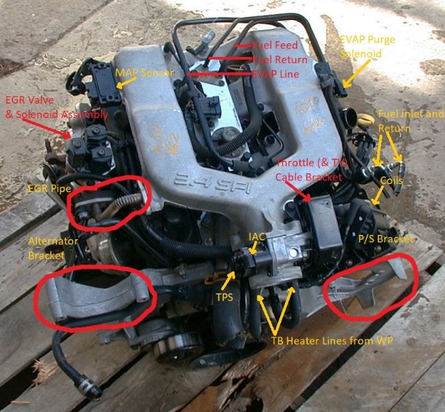
-
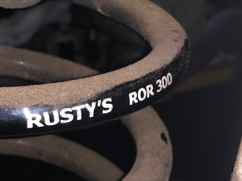
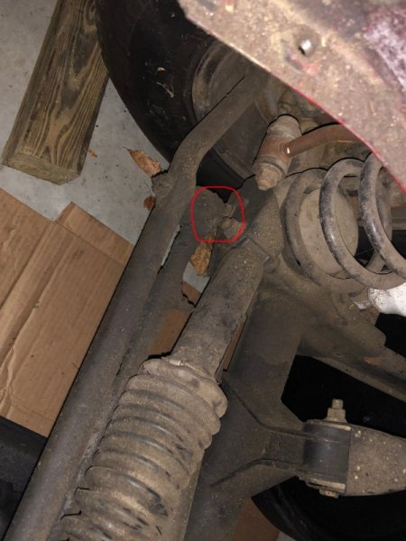
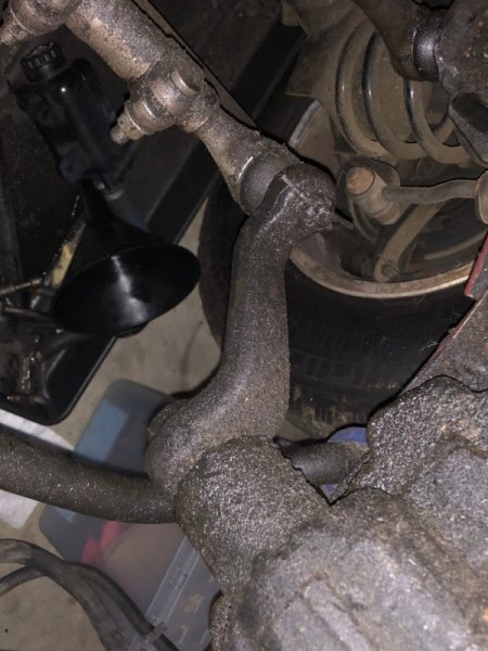
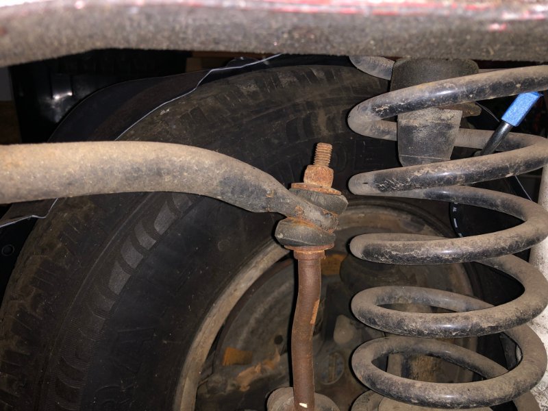
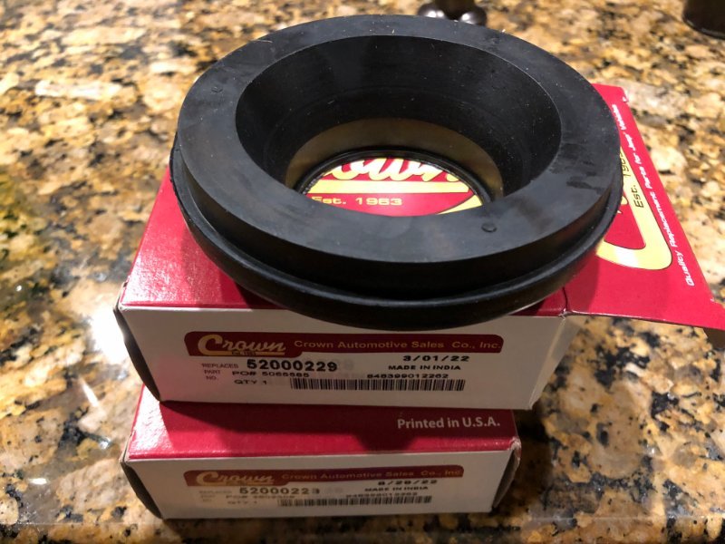
Turning attention to the front suspension and axle swap, I noticed this. I'd thought before this rig looked a little higher than stock height. Someone confirmed from pics I have sagged out leafs with AAL on the back, rear shackles might be longer than stock, hard to tell. Even before I noticed the springs, I saw that the proximity of the tie rod and steering damper was oddly close: Even with no engine weight on the nose, I thought the tie rod and drag link should sit lower so that begged a look at the Pitman arm, which looks stock length/ drop to me. Exhibit D - the sway bar appears in need of a drop kit (and seriously needs new end link bushings, at a minimum): These upper spring mounts arrived yesterday, apparently more parts are in order to sort out previous shortcuts:
-
Cool. I'm not the least bit intimidated by re-clocking the trans case. I'm jealous of JZLAJeep, very few XJs at all come through my local yards and all of them have been AW4-equipped and 96 and later, so AX-15 crossmembers are really hard to come by.
-
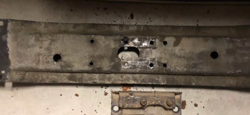
Aha. So this is a flat-topper, no additional drop in the center section. Which means re-clocking is an absolute must. But I shouldn’t have to beat up the floor, correct?
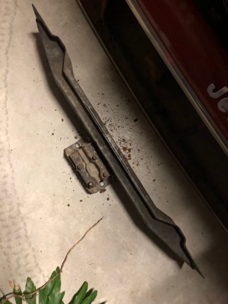
-
I'm looking at making what appears to be a crossmember for an AX-4 or AX-5 work with a YJ AX-15. My 87 MJ was originally 2.5/ AX4, but has been swapped to 4.0 and back to 2.5 before I got it. I'm pretty sure the trans behind the 4cyl was an AX-5. From all I can tell, crossmember 52002328 seems to fit everything offered behind a 2.5 through the end of 1987. 52002329 is for AX-15 89-90. What's going into it now is a 93 YJ setup, as mentioned above. Is there an obvious visual tell between the two crossmembers?
-
The difference is the rear half of the transmission case. I'm going through this right now/ soon. I got a drivetrain from a 93 YJ and have to re-clock it. The transfer case mounting flange on the back of the transmission has enough meat that the 6 holes could be drilled more clockwise for the YJ or more counter-clockwise for the XJ/MJ. That way all the 231s could be the same for either application and the trans could be drilled for whatever was on the production line. XJ/MJ are 10* counter-clockwise from the YJ orientation. I got a jig to do it. It bolts to the transmission flange where the transfer case would bolt up, and has a 2nd set of holes 10* to the left that guide drilling the new holes. One way of thinking about the difference between YJ/TJ holes vs XJ/MJ holes is like ignition timing. YJ/TJ is clocked 13* BTDC; XJ/MJ is clocked 23* BTDC.
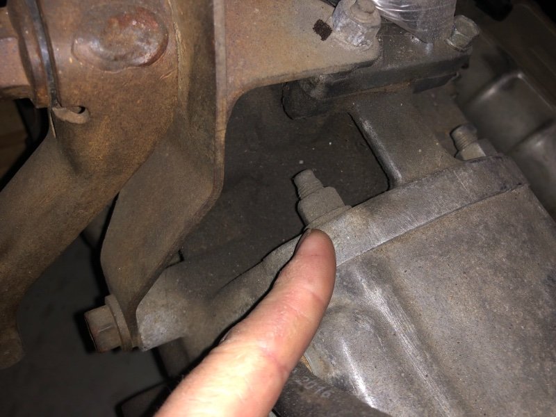
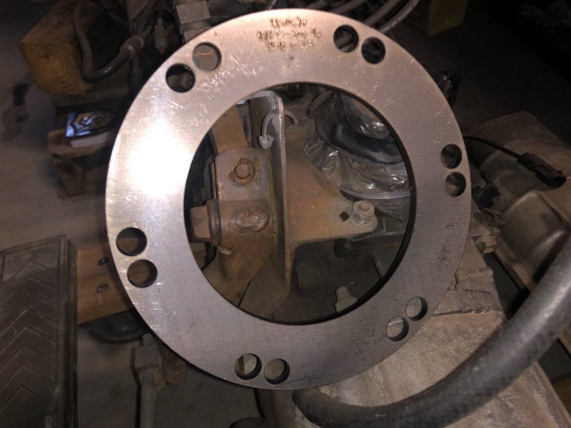
-
TBI or Carb? '86 2.5L to 3.4L upgrade
Gojira94 replied to FigurativeGarbage's topic in MJ Tech: Modification and Repairs
You're right, I got ahead of myself. 91-92 VSS is 2 pins and takes a changeable gear in the t-case or tailshaft housing. 1994 4L60E and GM's T5 read teeth on a gear that's part of the output shaft. A GM T5 would be the prospect of replacing the case entirely to use for 4WD or finding one from an old CJ. And the T5 is probably no better than the AX5 in terms of strength. Though they were offered to fit a 4.2 from 82-86 on the CJs, not recommended. There are AX-15 bellhousing adapters available for GM V6s. But given that the L32 is 160 hp @ 4,600 rpm and 200 lb.ft. torque @ 3600 rpm, and the cost and complexity of using it, makes getting the 4.0 rebuilt finding a used 4.0 or even rebuilding the 2.5 probably a more cost effective answer. -
TBI or Carb? '86 2.5L to 3.4L upgrade
Gojira94 replied to FigurativeGarbage's topic in MJ Tech: Modification and Repairs
In a "plug and play" situation with no modification, a manual trans PCM would be missing a lot of the auto trans parameters, though the tables would be there. There is a Flag set for auto trans that causes all those tables/ flags/ scalars to be read with a 60* 4L60E from 94-on. Speedo calibration and gear ratios would be the worst of your tuning. The pulses per mile in the VSS has a table to figure it against the gear ratios of the transmission, this is true for both auto and manual, and they are different from each other. To use a factory HO speedo, which works off a VSS, could be made to work, though not sure how to approach it without some thought and research. Also, the PCMs aren't locked so VIN isn't important. Though it can be easily read from the PCM and changed.