Gojira94
-
Posts
677 -
Joined
-
Last visited
Content Type
Profiles
Forums
Gallery
Everything posted by Gojira94
-
 Excellent read. It’s a general how-to for examining the 2 types Of injectors(peak & hold, saturated circuit) with an oscilloscope. It shows what certain problems with injectors look like on an o-scope. Prescient statement near the bottom of p.7 says the ‘latter’ type of injector that lacks an external resistor is slower, but durable and cheap to make. That’s the high impedance injector design we’ve lived with on through the 90s and beyond that are still popular and available for OE and aftermarket performance applications. It also states on p.7 that this ‘slower’ type can be compensated for by adding to the pulse width, which we’ve been doing for > 35 years lol. It’s a great general knowledge doc for its time, on how to scope and spot problem injectors, whether driven by amperage or voltage. Not helpful for unboxing the Renix calibration but a fun stroll down memory lane. And the science still applies. As for spray patterns, that’s why we use Bosch for Ford injectors on LT1 Chevy engines in the 93-97 Camaros and Firebirds and 92-96 Corvettes. Atomization is much better. And since Ford gives a data sheet with every injector, the calibration can be almost perfectly altered to use those Ford injectors effectively with accurate. characterization. I want the unicorn lol. An injector that’s essentially the 87-90, that’s doesn’t leak and has a 4 hole pattern, with the same voltage offset, minimum pulse width, breakpoint, etc.
 -
Injector Voltage Offset The 1987 Inj. MPI manual states the following, but nothing else about shaping the behavior of the injectors: "Battery Voltage: The battery voltage to the ECU is monitored so that the injector is energized for the proper amount of time. As the battery voltage to the ECU varies, the ECU varies the injector pulse width to compensate." When the ECU commands the ground to an injector to be closed, it doesn't open instantly and begin happily flowing fuel. The universe doesn't work that way.There is a measurable delay until the injector begins to open. Once it begins to open it can start flowing fuel. The above excerpt suggest that AMC & Renault made some effort to characterize behavior of the Siemens injector used from 87-90. They at least found out what the voltage offset is across a range of voltages. I don't know what voltage values the ECU uses, but I'd assume it at least includes values from 10.5V to 16V. 14.2 - 14.4 would be ideal, but if you turn on the A/C or are running accessories that draw away available voltage, as low as 11.9 - 12.2 might have to do. So the Renix ECU is programmed to add the voltage offset value to the pulse width to open the injector longer if voltage is below 14.4V and less offset time if above 14.4V. Minimum Pulse Width How long the injector has to be energized at a given voltage to fully open (pintle as far off its seat as it can go). At idle, the injector may not (likely won't) ever reach this pulse width. Below the minimum pulse width, flow may be inconsistent and cause issues, especially with idle stability. Again, this pulse width can vary across a range of voltages, but is generally understood and accepted to be measured and specified at 14.4V in the injector industry. Linear flow The pulse width, ususally measured in milliseconds, at which fuel flow from the injector becomes consistent. The battery voltage offset (time it takes for the injector to respond and begin opening) is added to the requested pulse width, appropriate to engine sensor input and requested power according to MAP, IAT, TPS, ECT. This is the point in injector 'on time' where the only correction needed is the offset time for whatever battery voltage the ECU reads at injector pulse. This usually happens in the fairly low off-idle range Static flow rate Open the injector all the way and measure how much fuel is delivered over a given period of time, say, in milliseconds. This can also be measured in grams/second, cc/minute, etc. Lbs/hour is probably the most familiar. However, just measuring how much fuel comes out of a wide open injector in an hour's time is essentially garbage data. Offset Adder in the very low flow range (idle to theoretically below idle and during cranking), since the flow rate isn't consistent, a little more fuel can be added. This low flow range delivers LESS fuel at low pulse widths because the injector is spending most of its time waiting to begin to open, opening and closing again. Very little of that commanded pulse width time is actually flowing fuel. The solution is to add a little more fuel as 'added pulse width' to compensate. So the injector is left open a smidge longer. Add a few microseconds or fractions of a millisecond time to the base pulse width, and decrease it as the base pulse width time approaches the linear flow point, where it's no longer needed. This adder usually drops out just off idle and above. I don't know if the Renix ECU has an offset adder in its programming. All injectors are not created equal Siemens Deka/ Rochester vs Bosch/ Ford style vs mystery meat vs high end injector shops: Siemens injectors from the late 80s through the mid-90s generally have MUCH shorter voltage offsets than Bosch/ Ford style. To illustrate the point: Drop same 'size' Bosch injectors into a vehicle programmed for Siemens/ Rochester and a significant portion of any fuel commanded is delivered late because of the longer actual offset time the ECU doesn't know about. The fuel/ air charge that enters the cylinder is leaner than it should be, and the leftover 'late' fuel puddles on the intake valve, as it's likely already closed. Then consider low pulse widths at idle - how different injectors behave below their linear flow rate will be different. The point at which their flow becomes linear will be different. So IF there IS programming for adding fuel at pulsewidths below linear flow, it will be wrong. The Renix ECU is something of a black box and there is no practical means of altering its programming to properly characterize any injector other than the one it came with. A high end injector shop like Injector Dynamics gives you a sheet with all the data above. These days, you can plug those values into your Holley, FAST, whatever EMS you're running and get near perfect injector characterization. "So and so injector works best..." You know why? Because you've tried an injector whose characteristics above are close enough to the originals to work well and deliver the right amount of fuel at the right time. "It runs much better but my gas mileage isn't better, maybe slightly worse..." You know why? The fuel delivery window the ECU expects doesn't match the voltage offset or low adder. However, the injector flows enough to make idle smooth and acceleration enrichment has more fuel than it needs to keep from going lean cracking the throttle, and/or you've upped the pressure a bit to make the engine 'happy' but send a lot of fuel out the tailpipe. Conclusion: If we can get our hands on the original characterization data that Bendix and Renault had when designing the 87-90 ECU and injector spec, we can understand what injector(s) can take its place. I'd also LOVE to see the hexadecimal (?) data tables that model the injector in the 1987 calibration, and any changes to that the OE engineers made in 88-90.
-
I'm trying to decide what fuel injectors to run in my Renix-controlled 87 project. I've done a large amount of tuning for Bosch/ Ford injectors on GM PCMs from 1994-2004. I can't stand the thought of blindly throwing "they work good" injectors at it. I hope no one takes this fuel injector sermon the wrong way, but it helps to understand my approach to injector selection for this project.
-
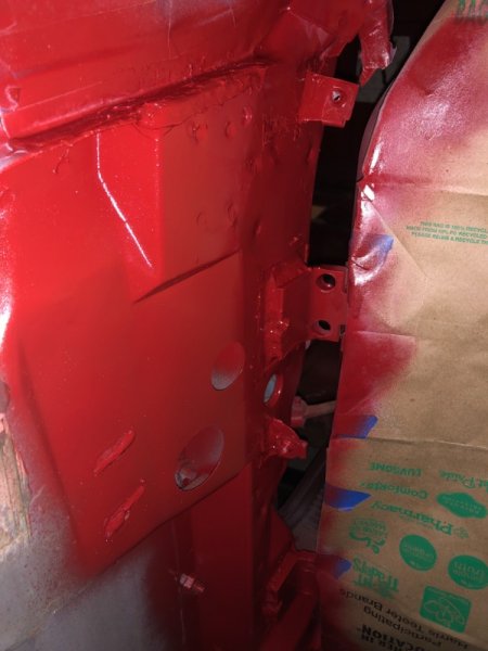
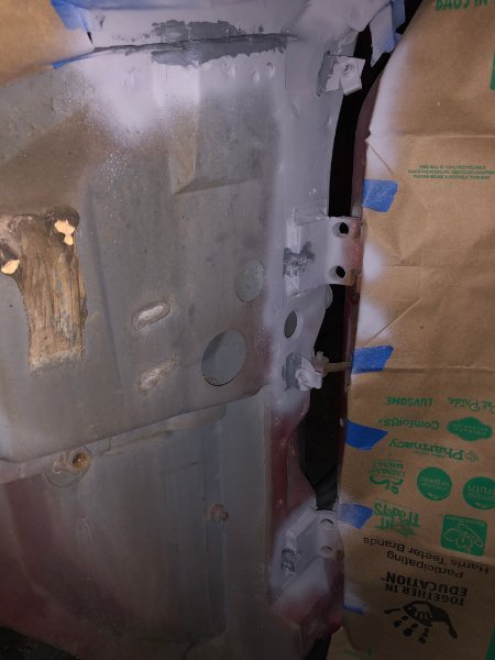
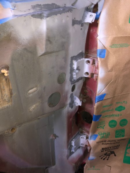
2 light coats of Colonial Red
-
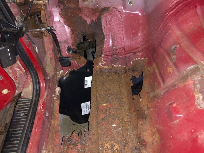
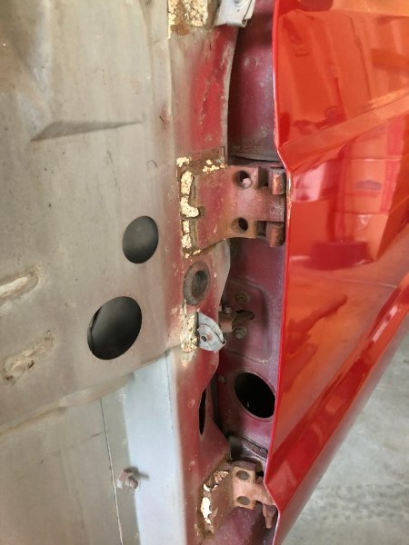
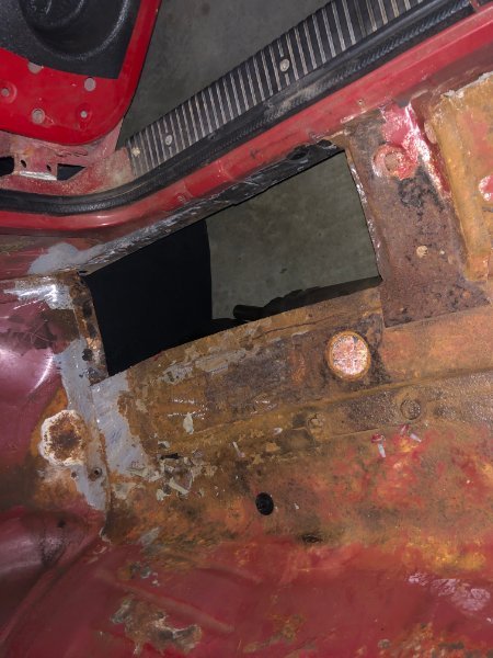
Door hinges and cowl seam sealer is like old crumbly mortar, I couldn't just pretend not to see it.
-
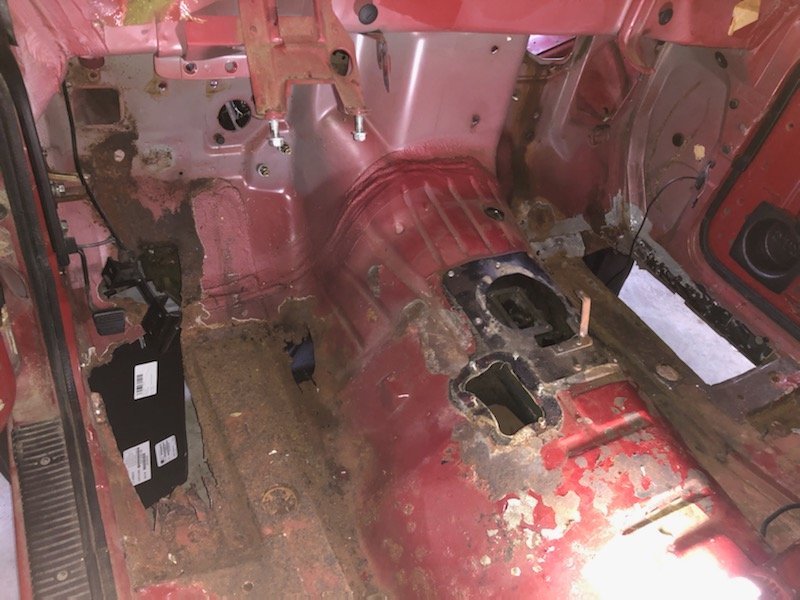
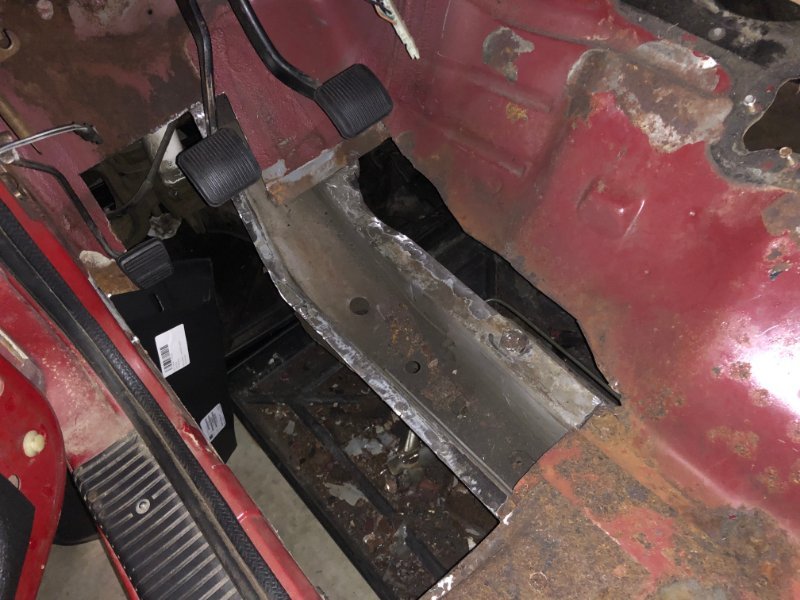
Main floor cutting done. Next I'll dress all the mating edges for welding in the patches and clean off the surface rust everywhere else.
-
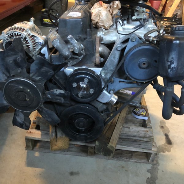
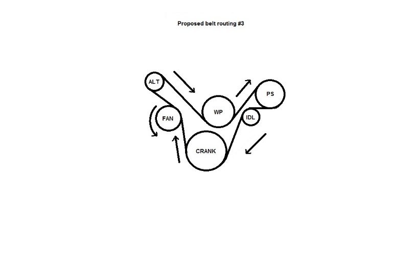
Engine front accessories mocked up. Alternator relocated up top. Still has the YJ PS pump and brackets. I may swap that over to 96+XJ since I already have the bracket, and it'll give more belt clearance for the lower radiator hose. From this: To this:
-
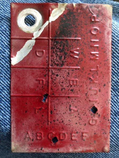
I have another thread active, trying to identify a body tag screwed between the driver's fender behind the valance. ever seen anything like it? https://comancheclub.com/topic/70269-help-me-decode-this-tag/
-
@eaglescout526 thanks so much for pulling the report!
-
1987, 2WD, 2.5l. Not really sure of much else about it, as it's been swapped and un-swapped and it's a basket case. Making it 4WD with 99 XJ D30/ front brake parts, swap to 4.0 and NP231 from a 93 YJ. Build thread here.
-
Found at the forward mounting point of the drivers side fender, while pulling the fender for seam sealer work. A numeral 1 punch and 2 diamond punches…
-
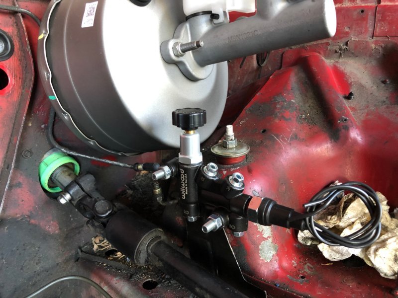
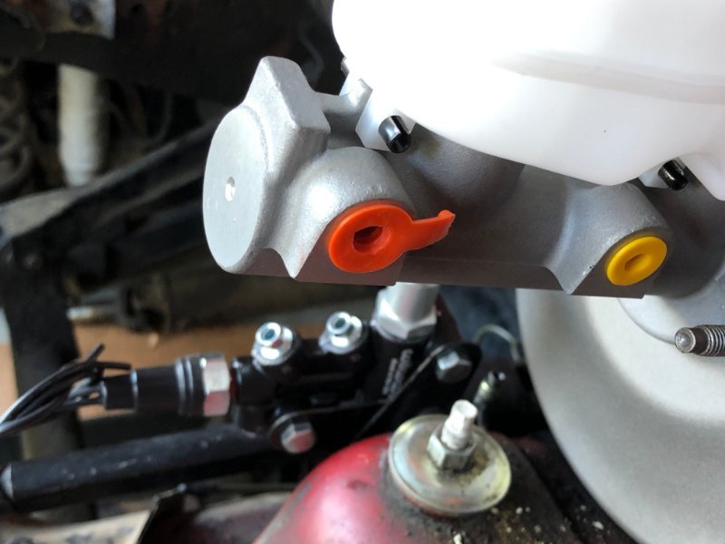
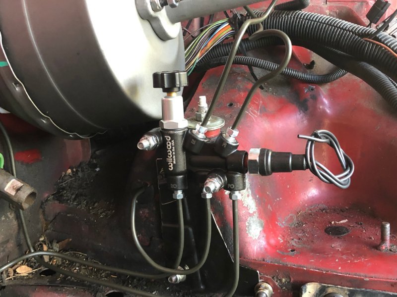
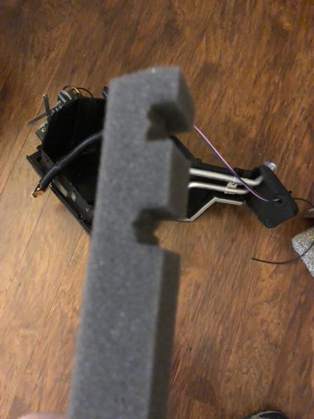
Scored a spacer off a 98 XJ at the local boneyard. Cleaned up pretty nicely. I'm going to hit the closed-cell foam 'gasket' with a light coat of FlexSeal before final installation. Wilwood valve test fit looks good. New lines all flared and attached. About 30ft of line, all bent by hand/ eye. AGS PolyArmor, pretty easy to work with and I prefer it over NiCopp any day. Pulled it all out except the valve to rear line for final floor cutting and engine bay paint prep...
-
brake line tools and flaring recommendations
Gojira94 replied to jamespwsullivan's topic in MJ Tech: Modification and Repairs
I just used this one to make 100% new lines for my MJ. I'll post up pics of that later today in my 'Basket case MJ' build thread. Nicest thing about it is you can even do it on the vehicle, which I had to do for either end of the rear feed line from the Wilwood valve, after bending and installing a 13 foot line, as well as the passenger side end at the wheel/ hose.... It only works with 3/16" line though. I really don't mess with flaring other tube sizes except GM transmission cooler lines but when stuff goes bad with a GM tranny, replacement of lines for $45 is how I go. Titan 3/16 double flaring tool British guy did a review of this/ a clone and it sold me on it. The Eastwood and clones are great but, again, for when you need to cut and flare an end that's a super-sized PITA to pull back out and flare, this is what will serve you best. Rick's Garage YouTube review of this tool I use a t-handle reamer to clean up the inner diameter after cutting and a medium-sized bastard file to deburr/ square/ slightly bevel the end after reaming. -
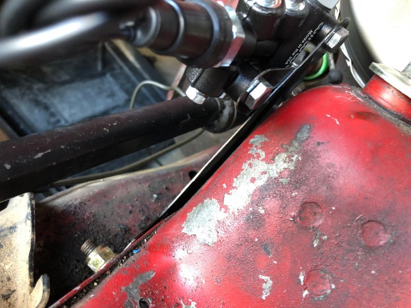
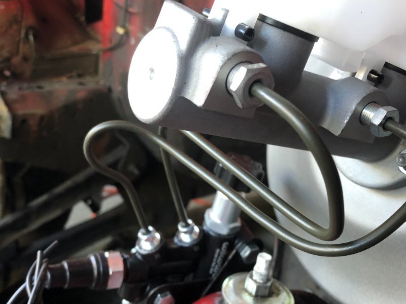
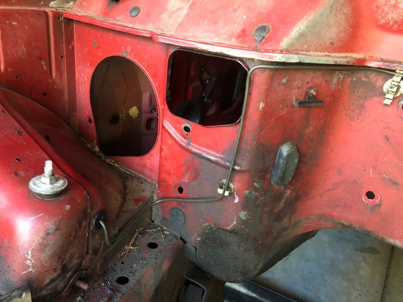
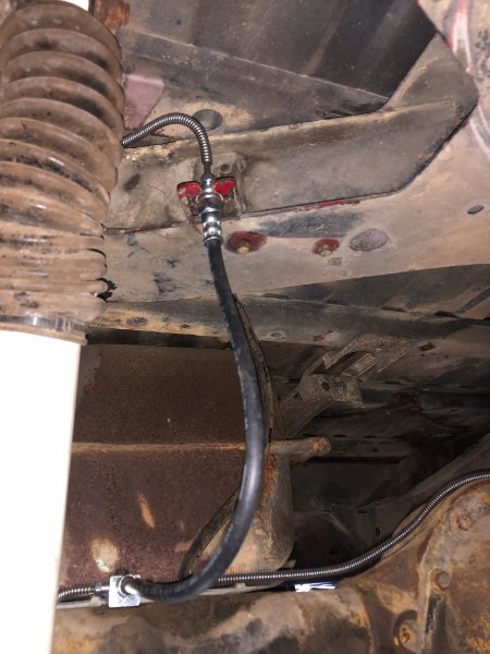
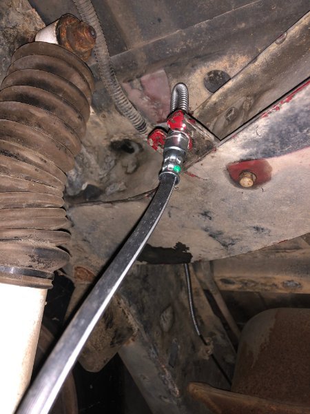
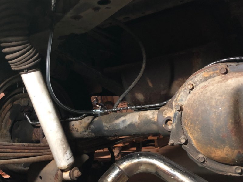
Brake line to the rear copied from the original, but run over the top of the X-frame with the rear lighting harness and dropped on top of the rear hose mount.
-
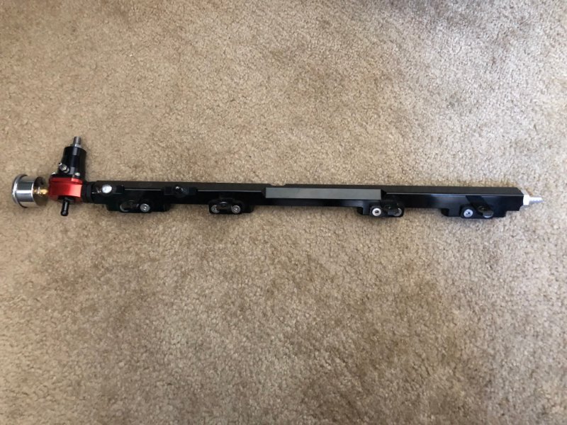
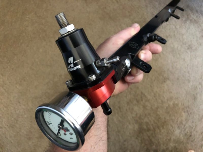
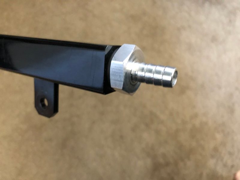
Here's my fuel rail. The guy I bought the engine/trans/xfer case from had some extra parts that came with it. He's going LS swap in his YJ so he threw in the extra stuff he never got around to installing. This rail is everywhere - Ebay, Amazon, etc. about $120, under brand "Fasster." The quick disconnect it had is now cut off and welded shut (the rail is sold for returnless systems, though the vendor does have a regulator/ gauge kit to go with it if you want). The ends are ORB-8 so I opted for quick and dirty, using an Aeromotive 13107 LT1 regulator I have on hand. I swapped out the F-Body LT1-specific fittings and put the inlet at the back of the rail. I could have gone fancy and done -AN stuff but fuel injection hose clamps are fine for 31-39psi. I'll probably swap the regulator out for an Aeromotive 13301 not too far down the road so I can put the 13107 back in the drawer as a spare for my Firebird.
-
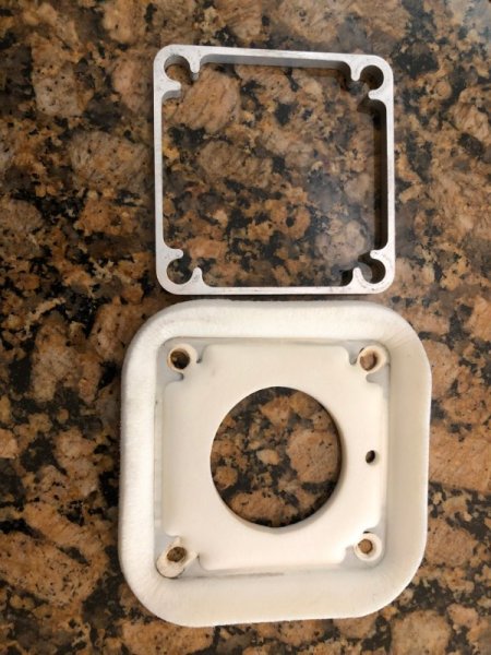
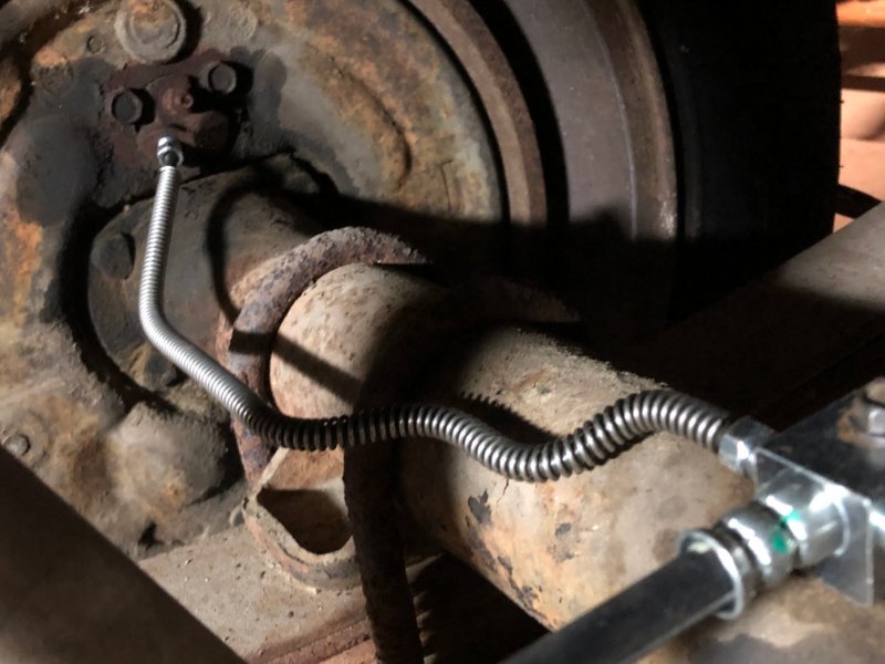
It's been a while since I made brake lines. I made copies of the 2 on the rear axle, which came off ok but the nuts are really crusty. The gravel guard wire came from a US family company in Ohio, through Amazon ("The Stop Shop"). Line is AGS PAC-325 PVF coated with 3/8-24 inverted flare nuts (also AGS). I have them mocked up with an 18" hose for 95 & up XJ (O'Reilly auto BH622067). I deleted the rear valve so the hose will mount in the factory tab next to where that valve used to mount. I just have to make single long line to the Wilwood manual valve going up front. 95-96 brake master arrived yesterday, matching booster coming tomorrow. I can mock that all up and run lines and then yank it back out and sort out the engine bay clean/ paint. I'll be making a bracket for the manual brake bias valve, from one of these 2 SBC plug wire mgmt plates I've got lying around. The mounting studs for the 2.5L bracket location should be a good anchor. A little bending and shaping and I can make it clear the steering shaft and keep it away from the exhaust.
-
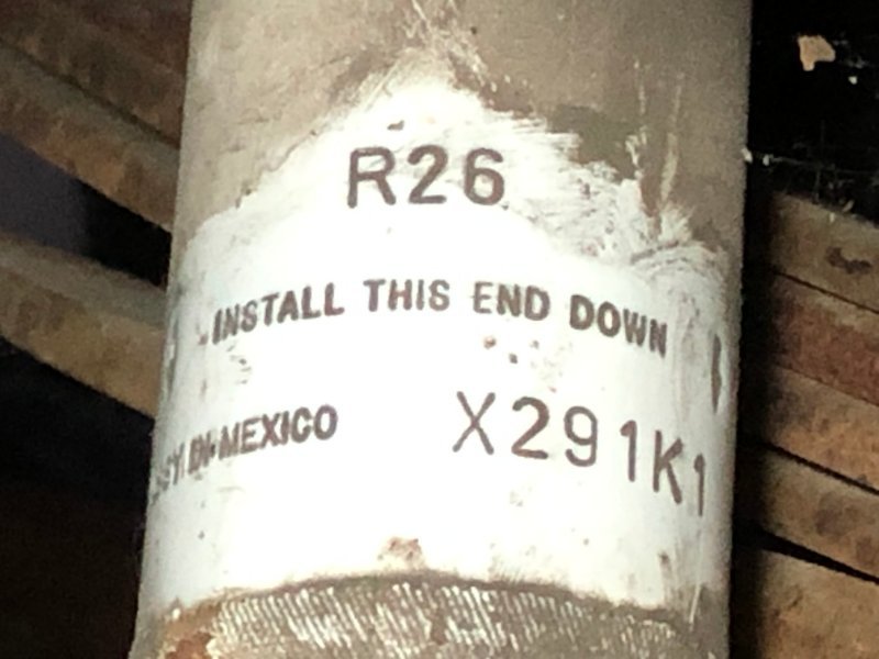
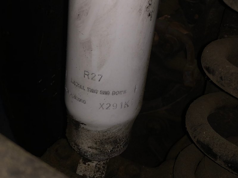
Help me identify shocks, rear leafs
Gojira94 replied to Gojira94's topic in MJ Tech: Modification and Repairs
Might be something else up inside the boots, but those are zip-tied around the upper tube body at the moment. -
Help me identify shocks, rear leafs
Gojira94 replied to Gojira94's topic in MJ Tech: Modification and Repairs
Thanks for the info - this one spent time next to another MJ before I got it ("make one good one from two" situation), so many surprises are here to be found... If I'm shopping for shocks soon I need to have some idea what length I'll need. Edit: just a D35 back there with 3.55 gears. -
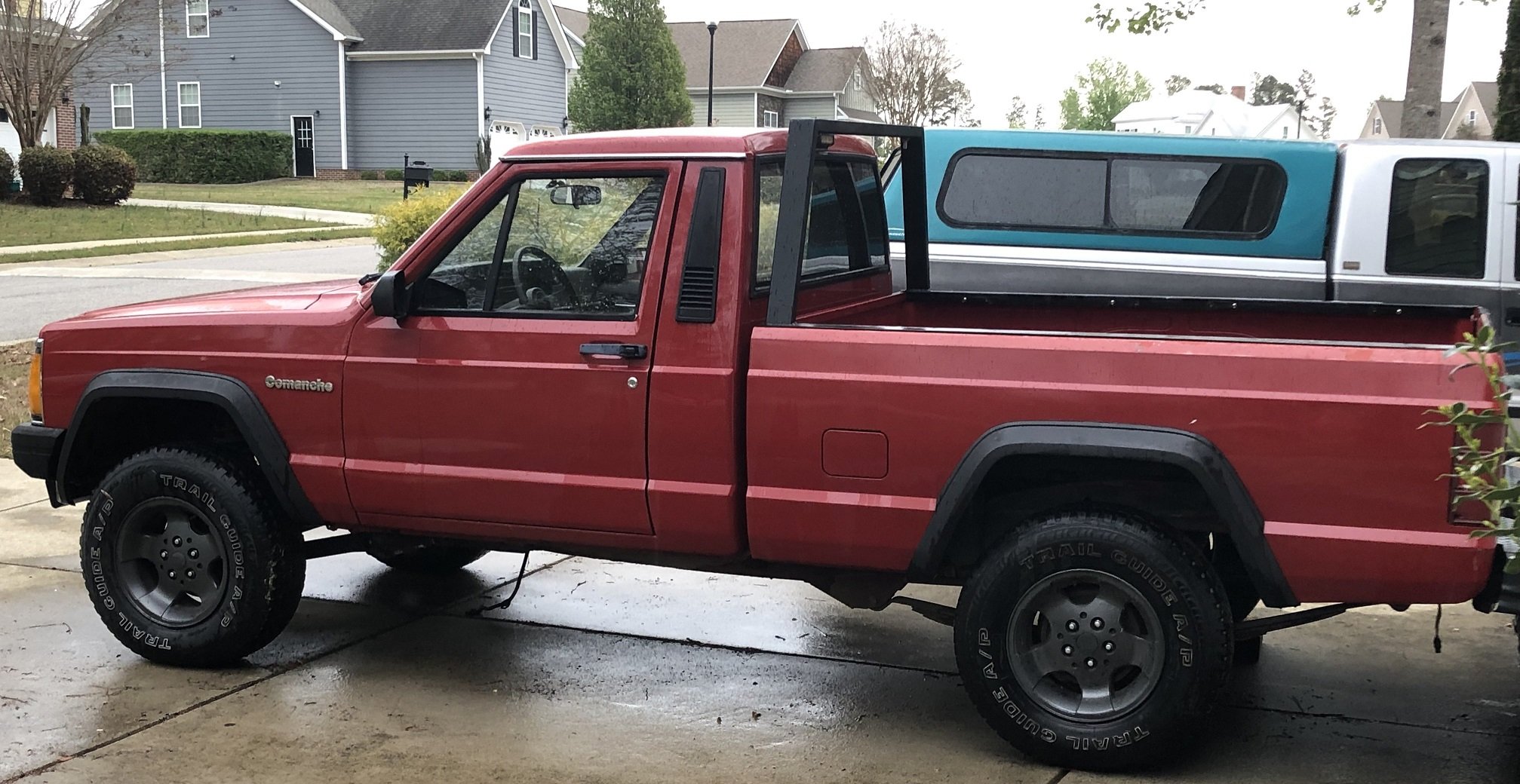
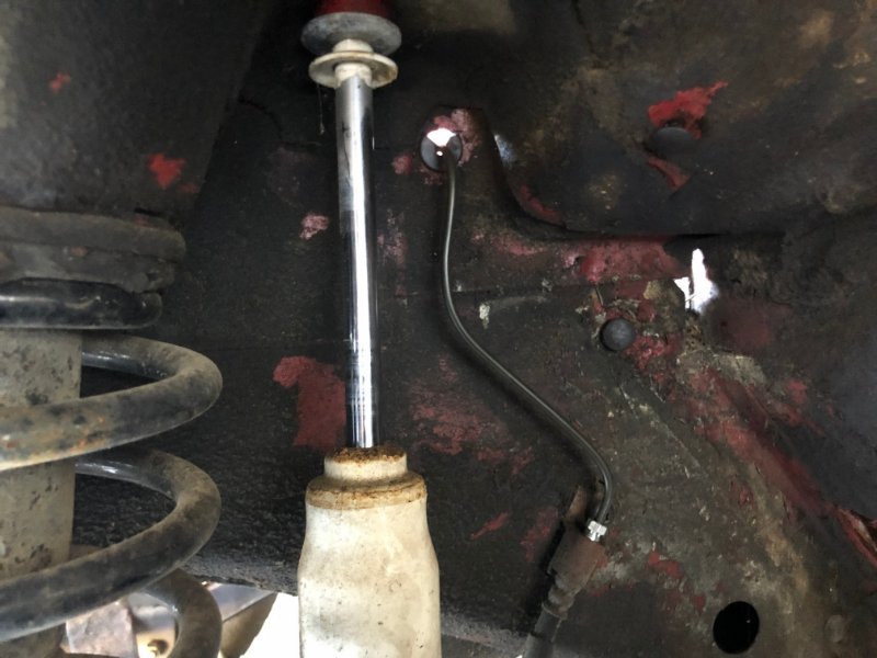
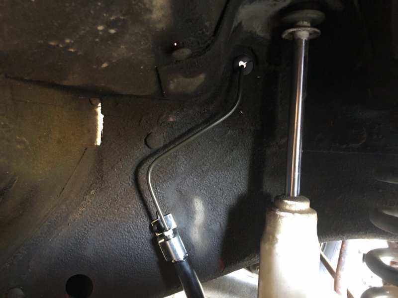
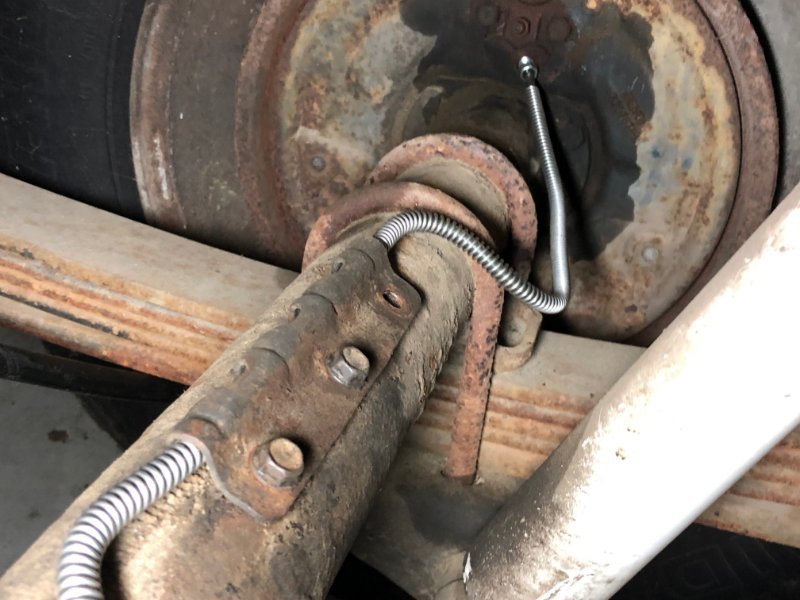
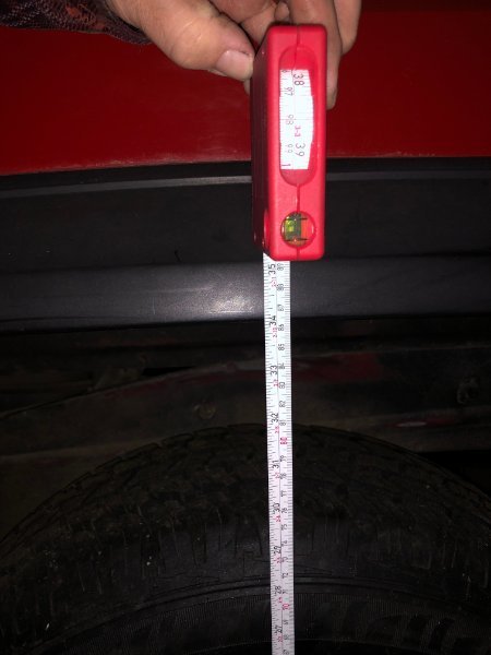
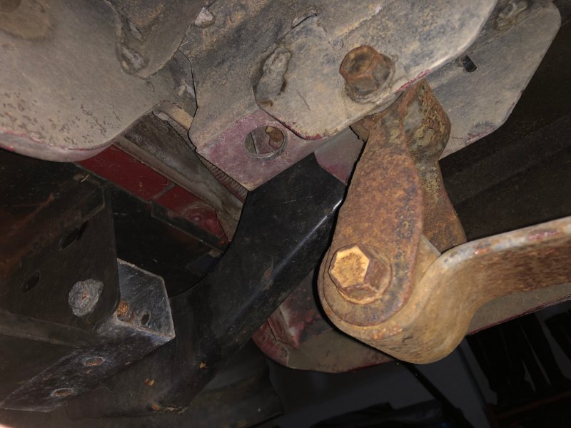
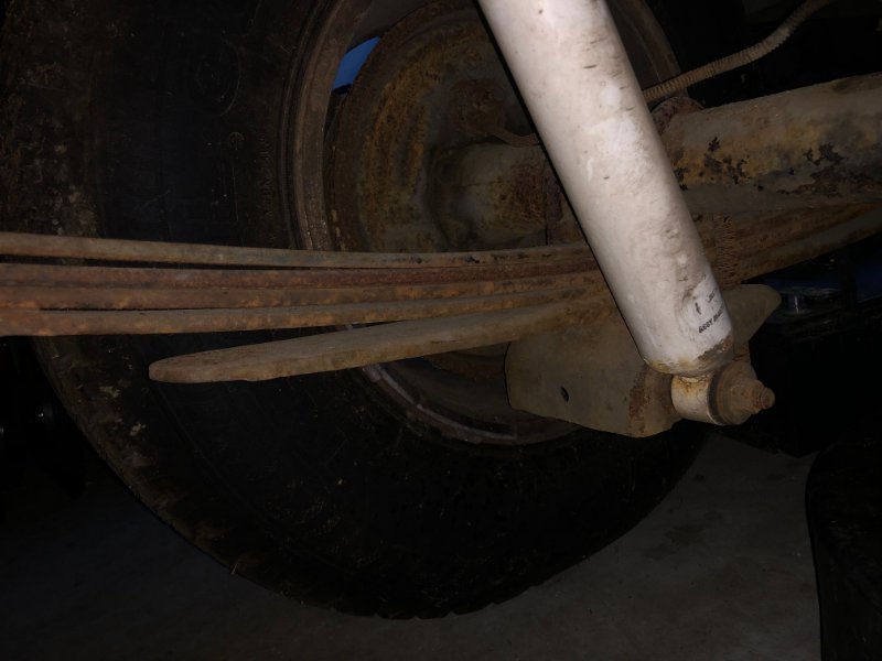
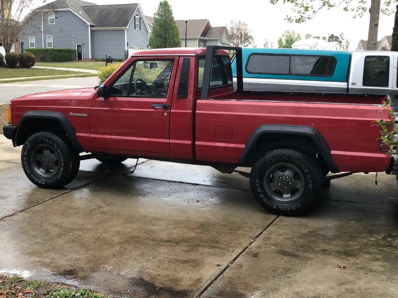
Front shocks: Rear: Rear leafs have 5, shackle at the back looks stock: Rear wheel well opening sits at 34" and about 5.75" clearance to the 235/75R15 tire it sits on. Pic from the day it showed up, just after a wash. Does this look lifted or is it just me?
-
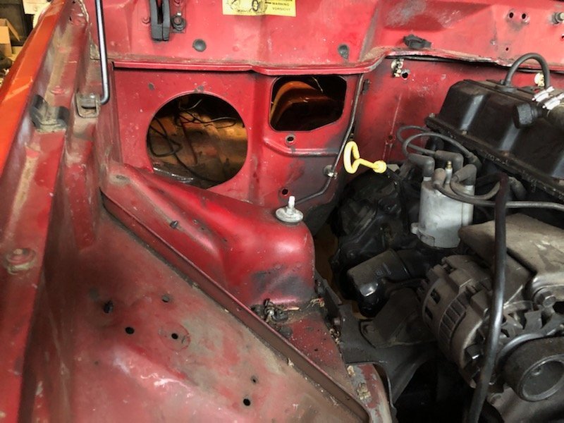
Also, finally got the engine bay clear the other day- went to a father/ daughter project XJ not too far from here in NC, so I can finally start the clean and prep for engine bay paint and floor repair, and then get the Dana 30 under it. Interior can then go back in and engine work can begin. I'm also in the process of sourcing good quality but cost effective parts for brakes (pretty much all new parts from 87 rear brake stuff, 95-96 booster/ master, calipers, pads, rotors, hoses). Saw Big_Mark's build thread and MTS Company still is around and has the JPSU-6P4.0 sending unit/ pump assy available. Once brakes and fuel are squared away I can get down to final mechanical details, including Renix flywheel and clutch kit and new internal (for now) clutch slave. I don't know what's up with my supplier of the trans case reclock jig, ordered in July. I still haven't seen it, haven't gotten any responses from calls. I may just bite the bullet and take the trans to my machinist in Raleigh and have him do it.
-
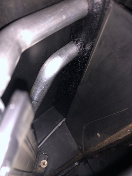
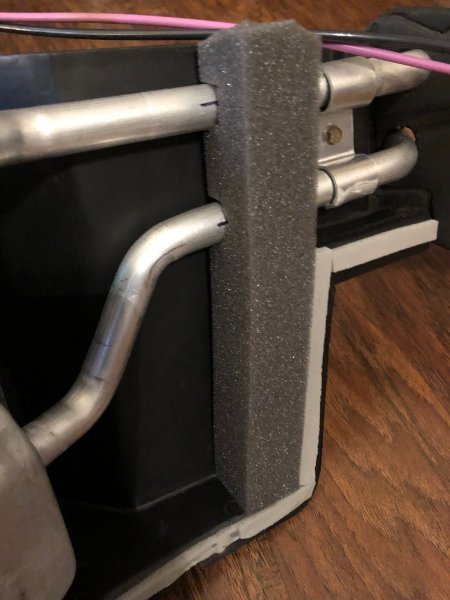
Air box, continued - the seal to keep air from bypassing the route to the heater core/ evaporator for A/C equipped vehicles is going to be no good after so many years, I got some simple window air conditioner foam and coated it with 3 light coats of flex-seal, with custom trimming around the heater core in/out:
-
Glad those boxes went to good use! By the way I'm also a huge fan of tan/saddle/camel/taupe interiors with forest green metallic bodies. My 94 Firebird has that combo and I love it. Also prefer it for red and black vehicles.
-
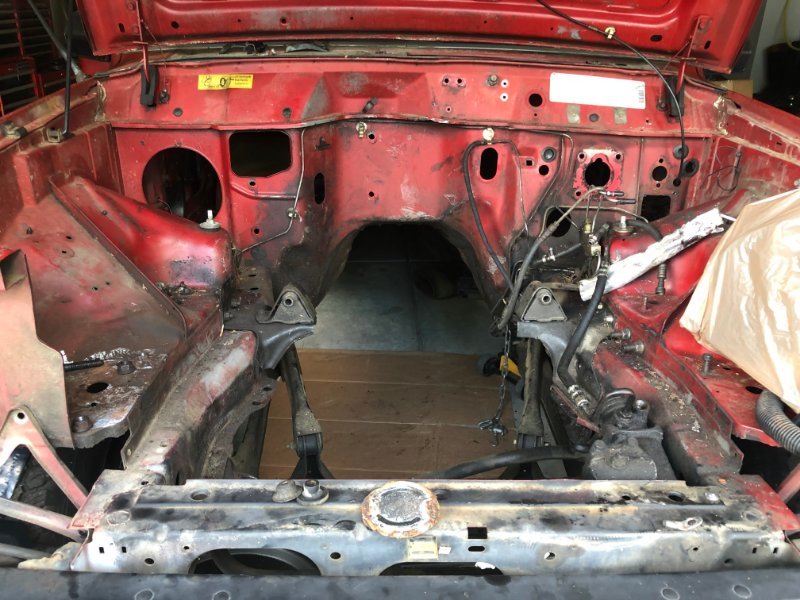
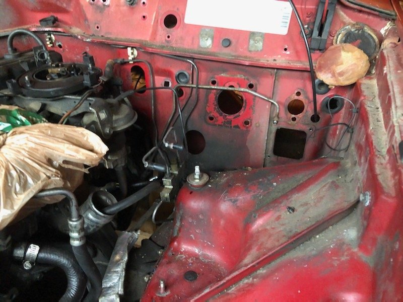
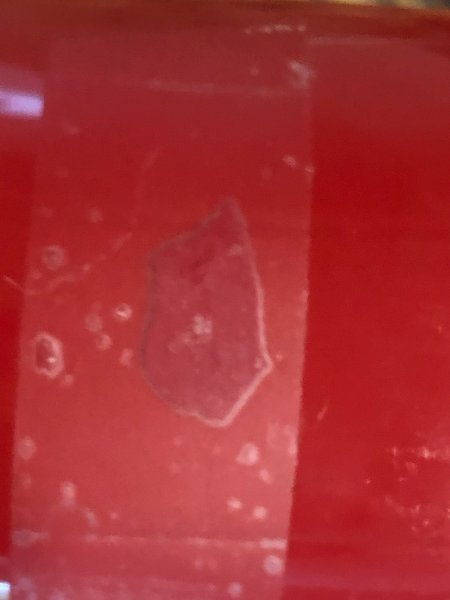
Firewall side of things. This 2.5l has become the albatross around my neck. I'd let it go for free (now $100 with AX-5 on Craigslist) but I don't want to attract the meth head scrappers in my area, to scope out my place while they're picking stuff up. PLEASE come get this thing for FREE if you're within range lol. Duplicolor only makes Colorado Red in a 2oz. touch up bottle/ pen/ whatever. However, Rustoleum's Colonial Red is close enough for spraying the floor and engine bay after I get them cleaned and prepped. This first pic under scotch tape against the cap on the can turned out as bad as I thought, looks better through a plastic bag on top of the cap. This chip came from the floor pan so it's never seen the light of day since March, 1987 (I was a junior in high school). For the engine bay I'll follow it with at least one coat of a ceramic clear for durability.
-
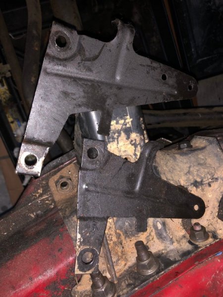
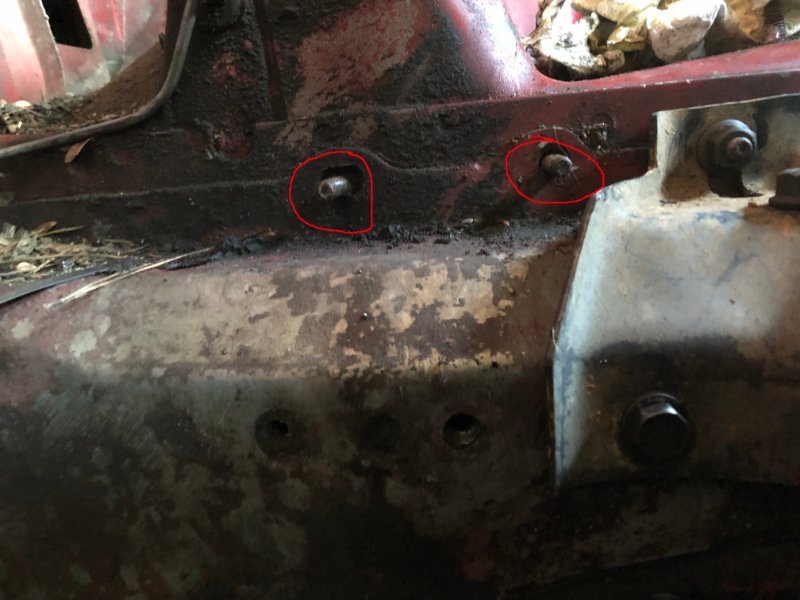
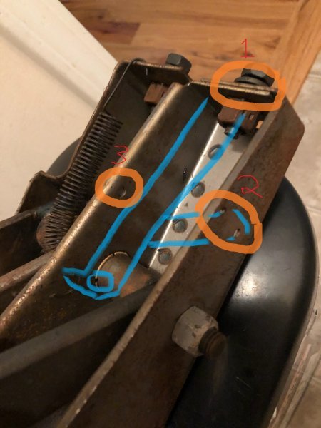
Brakes plans... The rear parking brake cables are missing but being the only real rust in this thing is in the floor, all the brackets are there and good to go. I'm going 95-96 booster/ master, 97-01 calipers/ pads/ soft lines. Leaving the rears drum for now, probably won't convert to disc anytime soon, if at all. The rear load sensing proportioning valve is there but the rod is gone, so it's getting deleted and the front valve will be a Wilwood 260-11179. I've read of issues getting the brake switch to work reliably with grinding the rod on the 95-96 booster so I'm trying something different. Make a bracket that mounts on the 84-90 manual pedal assembly upper bolt for a traditional adjustable 2-pin brake switch. This is a pic of my 87 pedals. There are holes on either side, 2 inboard, 1 outboard that can be used to mount a support brace for the longer piece of the switch bracket. Just an idea, the pedal assemblies on Ebay used, for a 95-96 are just under $300, so nope.
-
Now I'm ready for the floor pan work and subsequent re-spray of the interior metal on the floor. Extensive cutting needed on the driver's side. The upper brace on top of the floor pan is too far gone to save. Passenger side cleaned up ok, not nearly as bad. Passenger side will get a patch of the outboard half, cleanly against the door sill. There should be enough left from the back part of the driver's side replacement pan to make a patch for the firewall behind the pedals.