

Gojira94
-
Posts
718 -
Joined
-
Last visited
Content Type
Profiles
Forums
Gallery
Everything posted by Gojira94
-

Adding 94-96 XJ A/C to 87-90 MJ - Slow Thread
Gojira94 replied to Gojira94's topic in MJ Tech: DIY Projects and Write-Ups
I went back to the boneyard to a 1988 XJ and got the missing pin C / orange wire for C109. I also got the fan diode with radiator temp switch connector attached for my visual reference. And the A/C Clutch Relay socket/ pigtail (which it turns out I won't be using after all). I'd decided against cutting into the 1990 engine harness. I'm going to clean it up a bit, do a few minor repairs around the EGR & ballast resistor connections and offer it up to anyone who might need it/ want it for an 89 or 90 rig. I paid $59.50 for it, so +$20 and shipping cost and it's yours. PM me if interested. I also ordered a 1996 evaporator and started cleaning up the 1990 HVAC housing. I can see that very slight modification will be needed. The height is over by about 1/4" from perfect. Front to back fitment is good-ish but I'm going to massage the back/ cab-facing lower portion of the box to gain about another 1/4" front-back clearance and settle the rear of the evaporator down about 3/8." It's very close to right and I could probably install it and go with it as-is but my OCD won't let me... pics later. -
Adding 94-96 XJ A/C to 87-90 MJ - Slow Thread
Gojira94 replied to Gojira94's topic in MJ Tech: DIY Projects and Write-Ups
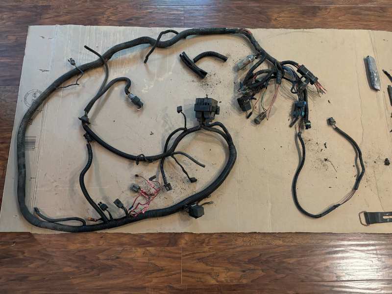
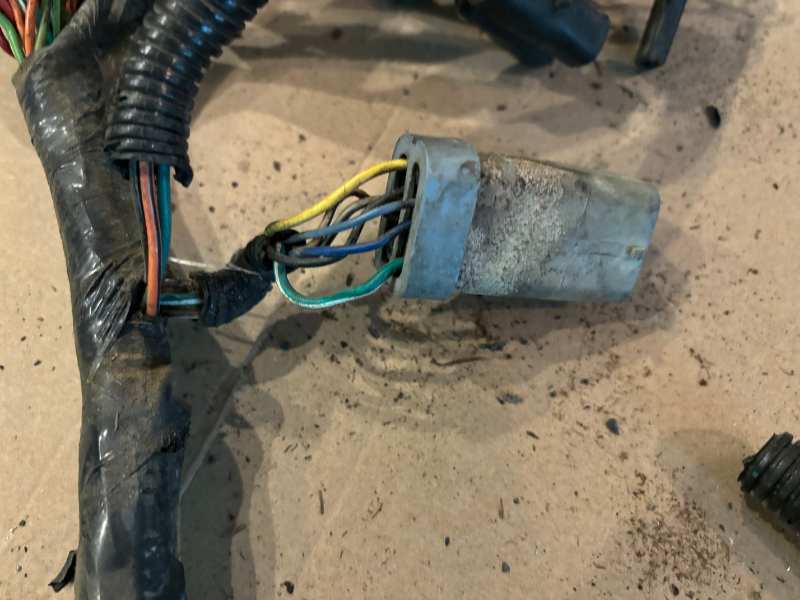
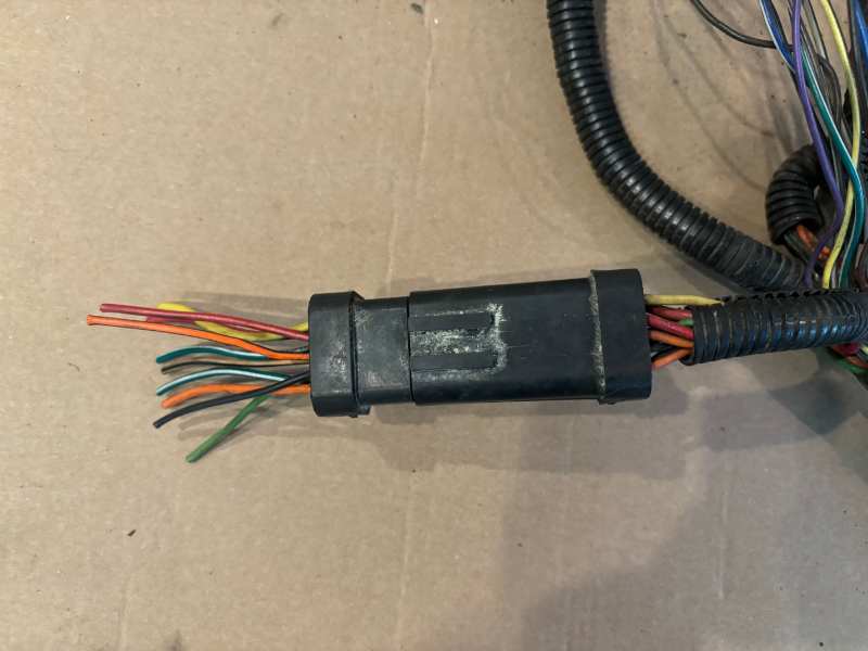
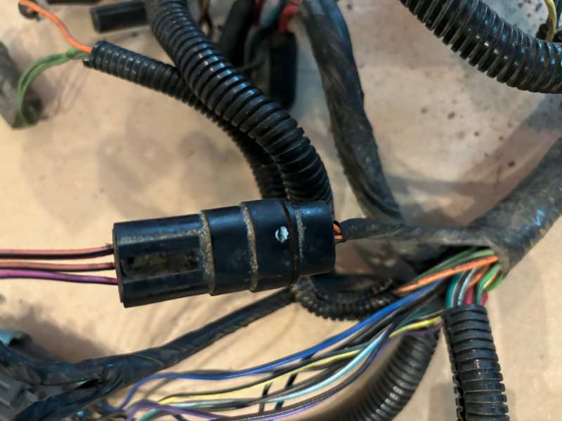
First update - the trip to the boneyard was a success. Heater housing bare - $22.50 Temperature control - $36.00 Wiring harness engine - $ 55.50 ======================= Bonus items: Engine control module - $82.00 Shifter bezel - $14.00 ======================= $225.20 with 7% tax... Computer is a 56006078 - According to an old post by @HOrnbrod, "Renix ECU 56006078 is an alternate (superseded) part number for ECU 53005406." Mini console has unbroken mounting tabs, so I grabbed it. I thought I was smart for going for a 1990/ last year of Renix engine harness. However, this was when Chrysler was starting to dig its fingers into stuff and they unified what would have been 'Engine to Alternator' C105 & C335 on 87-89 88 into this, below (EDIT - 1989 also has these connectors, so C105 and C335 unified into the grey Chrysler connector was either a mid-year 1989 change, or covers all of 1989 MY production): They also made a change and unified what would have been C103 (6-way) & C109 (4-way) on 87-88 into this 10-way, below: They left C104 alone (10-way). There is also this connector I haven't figured out yet. Where it went was low on the passenger side into a really dirty area I wasn't in the mood to dig into since I was about to tear into the dash. 3-way mystery connector below: My verdict is that I'm going to harvest what I need from this harness, rather than trying to use it complete. Yes, I could go get connectors I need from an 87-88 and convert back the changed Chrysler connectors splice them in. I can't be 100% sure C100 is the same as what I have now on a 1988 non-A/C-equipped engine harness (with dealer install connector C117). For me it would be no big deal if I'd had to splice in the fan diode and A/C Clutch Relay and the C100 pins G5, H1, H4 if needed for A/C Request & A/C Select. I've already cleaned up, gone through, and made the modifications for electric fan and fog lights on the harness I already have, and everything else works well the way it is. Better the devil you know than the one you don't. I do already have a (now 100% confirmed) 1989 Engine Control Harness that does have A/C provisions, that came with the project from the beginning, and it's perfect. And it also explains why my trans harness pass-through connector at the ECU connectors from its reverse lights connector is different from the 87-88. And I had to cobble the 2 together to get reverse lights working a while back. Next up is to clean and prep the heater housing. The temptation is to get an evaporator ready in it and when the cool days come back to NC, swap it out with my heater core in it and be done with the cab side of the swap.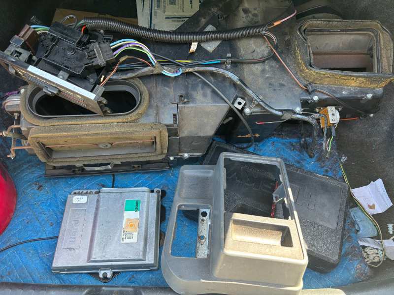
-
Looking at the back of the new connector on the new motor, where the wires from the motor go into the connector, if these are the colors: ___________ | X 2 3 | |_4__5__6__| Then: New motor/function/old connector color: X (no pin/ no wire) 2 White - Park - goes to Gray wire of old connector 3 Red - Switched 12V - goes to Blue wire of old connector 4 Yellow - High - goes to Red Wire of old connector 5 Green - Low - goes to White wire of old connector 6 Black - Ground - goes to Black wire of old connector
-
It's going to take a while to gather everything I'll need to do this. I'm guessing it'll take 6-9 months to gather it all and be ready to do the install. I've chosen to do a hybrid setup, using Renix-era inside parts, aside from the evaporator itself. Under the hood, I'm opting for a 94-96 R134a native setup. I don't like the 97-01 setup that uses stamped metal clips to hold the lines together at the condenser, no thanks. And 87-90 to me looks cluttered and the hoses and parts are hard to come by from what I've seen in discussions here. My engine control harness is from 1989 or 1990 and it has the pins for A/C. My engine harness is from something else and does not have the diode module, A/C clutch relay, clutch feed or pressure switch connectors. I can make all that from parts cut from an 87-90 in the boneyard, or buy the whole harness at the boneyard for about $60 and recondition it. I have the 91-98 compressor mounting bracket, my alternator is sitting on it right now. I'll have to move the alternator down to the original HO location and get a pair of HO alt mounting brackets and shave them for my Durango unit. And a new belt. The remaining parts needed are as follows: HVAC Housing - 87-96 boneyard rehab Temperature Control Panel for A/C equipped car - 87-96 boneyard rehab A/C Dash Harness - 87-90 boneyard rehab A/C Thermostat Control Switch on HVAC box - 87-90 boneyard grab or new Crown 56002688 from Quadratec.com Evaporator - new 1994-96 Evaporator drain tube - 87-96 boneyard rehab Expansion Valve - new 1994-96 Low Pressure Cutoff Switch on drier - new 1994-96 -OR- binary switch Santech MT0484 Receiver drier - new 1994-96 Compressor to condenser hose - new 1994-96 Low Side TxV to compressor hose - new 1994-96 Condenser to drier hose - new 1994-96 Drier to High Side TxV hose - have to have one made after all Compressor - new 1994-96 Condenser - new 1994-96 Condenser to radiator mounting tabs - 87-96 boneyard rehab + new hardware for them I'm going nuts right now because I have a source vehicle located for some of the big items. But there's no way I can get to it until the weekend of August 8th-9th 2026!
-
What should I do while the carpet is pulled up?
Gojira94 replied to jodawill's topic in MJ Tech: Modification and Repairs
For the sake of posterity and documentation, what's printed on that yellow label on the tunnel? Or is that just a business card lol? -
That didn't work. No cruise engagement at all. Now set to 10:00 / back to 8:45 / MAX. I need to move some stashed furniture from a move at the coast I helped with, out of the garage, before I can pull it out again...
-
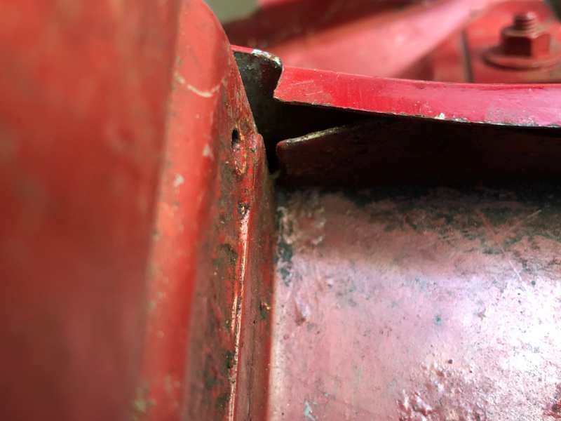
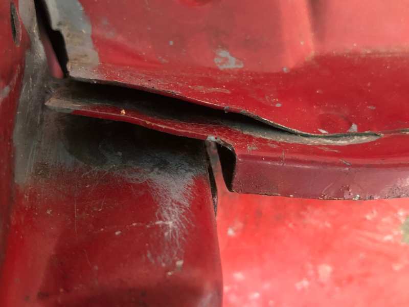
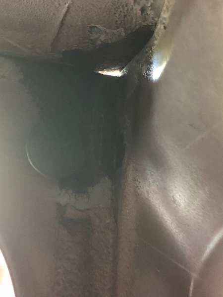
I spent 3 days working on that spot. I got all the seam sealer out of it and opened the outer cowl layers with a chisel. Worked it with a flat hobby file (tiny), guitar strings and steel brushes. Sprayed the hell out of it with rust converter, primed it. Then filled it to the moon with new 3M seam sealer and worked the layers back together with a brass drift while the sealer was still wet.
-
MayDay!! - Hard Accel Killed Idle
Gojira94 replied to AnotherOldJeepGuy's topic in MJ Tech: Modification and Repairs
Before, I was surprised the EGR was responding in Park just off idle, but there were a lot of other factors in question that needed to be addressed first. EGR should be operating in a transient part throttle state, in gear, car moving. I think what you see now is normal EGR operation. EGR valves are very simple mechanical devices. The parts on cars with EFI, that tell them what to do and when, sometimes more complicated. -
MayDay!! - Hard Accel Killed Idle
Gojira94 replied to AnotherOldJeepGuy's topic in MJ Tech: Modification and Repairs
Absolutely no hurry whatsoever. Let’s get you all the information possible and answer all questions first -
2005 Volvo V50 2.4i Repair
Gojira94 replied to Gojira94's topic in Member Projects: Other Cool Stuff
Thank you -
2005 Volvo V50 2.4i Repair
Gojira94 replied to Gojira94's topic in Member Projects: Other Cool Stuff
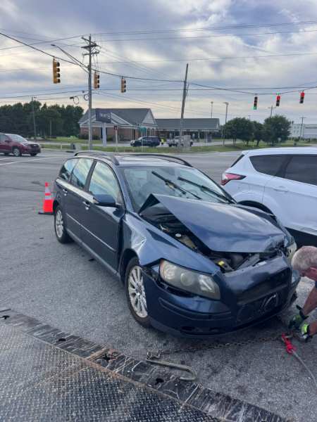
Sad end to this story... My 23yo and 14yo daughters are ok. The car did its job and kept them safe. But "Valerie" is no more. My oldest daughter got married in April and traded the other wagon for something newer she likes a lot. So no more P1 Volvos in the stable. The only Volvo left is the 2010 XC70 3.2 (wife's car).
-
Of course you're right - that this is minimum set speed as well. Had myself some tunnel-vision chasing this through every component for several days. So it's both minimum set speed and the lowest speed resume will work. i.e. if you were cruising at 65 and braked and slowed to 20, you'd have to get above the minimum speed before the resume button would be able to pull you back all the way to 65.
-
MayDay!! - Hard Accel Killed Idle
Gojira94 replied to AnotherOldJeepGuy's topic in MJ Tech: Modification and Repairs
Good on ya for pressing onward. A lot of folks don't have the patience to go through it all, ask for help/ advice when needed and would have given up. -
EVAP connect or delete on new Rough Country CAI
Gojira94 replied to Motorhead X's topic in MJ Tech: Modification and Repairs
Looks good. Nicely done. -
EVAP connect or delete on new Rough Country CAI
Gojira94 replied to Motorhead X's topic in MJ Tech: Modification and Repairs
Just stuff I had lying around. Same diameter as the main evap tube from the canister. -
EVAP connect or delete on new Rough Country CAI
Gojira94 replied to Motorhead X's topic in MJ Tech: Modification and Repairs
I got one of those open box for 1/2 price. I popped a hole and grommet n it and connected it. Used a piece of 45* rubber hose and a short piece of tube to make the connection on the intake pipe due to the angle.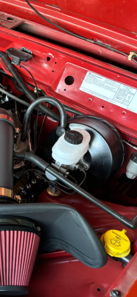
-
MayDay!! - Hard Accel Killed Idle
Gojira94 replied to AnotherOldJeepGuy's topic in MJ Tech: Modification and Repairs
Platinum. Significantly higher resistance than copper. I'd suggest replacing those (I'm sorry!) with Champion 404/RN12YC (about $6 each). The platinum plugs are not a good match for your wires. -
MayDay!! - Hard Accel Killed Idle
Gojira94 replied to AnotherOldJeepGuy's topic in MJ Tech: Modification and Repairs
Old plugs and new plugs are copper, right? No platinum, not iridium (especially) or anything else but copper Champion RN12YC at .035" gap? -
MayDay!! - Hard Accel Killed Idle
Gojira94 replied to AnotherOldJeepGuy's topic in MJ Tech: Modification and Repairs
Your current wires look like the same NGK wires I'm running. 500 ohms or less per foot is very good. You don't want higher resistance wires, no. And for misting the wires while running, no soap needed. That process is meant to find damage to wires from contact with hot things, damage not visible to the naked eye. Current moving across high resistance looks for shortcuts to ground, so low resistance/ internally well-shielded wires is what you want. -
Green 1974 Volvo 145DL. The beginning of my relationship with Volvos hahaha. I cried when it got used as a trade in for my step-sister’s new 1990 Accord Coupe. They got $100 for it. Failing transmission and Flintstone power with only 247,000 miles on the clock. I’d love to have another one for a stealth turbo LS swap.

-
"Beavis, this is the coolest thing I have ever seen..."
-
Dana manual says to set cruise around 45MPH, brake and slow to about 18MPH. Then press and hold resume/accel and manually accelerate slowly until the gas pedal starts to pull away under your foot, accelerating back to previously set speed on its own. The speed at which that happens is the "Low Speed."
-
I found this pdf guide for Dana cruise equipped motor homes. I think it refers the slightly older purple regulators but they work the same aside from a wire you cut for manual trans applications. A good read and goes into more detail than the 88 electrical manual pdf I have a copy of. DANA CRUISE CONTROL TROUBLE SHOOTING GUIDE.pdf
-
MayDay!! - Hard Accel Killed Idle
Gojira94 replied to AnotherOldJeepGuy's topic in MJ Tech: Modification and Repairs
Absolutely, hang on to it. -
Regulator adjustments pots on my regulator ohm out as follows, will vary some with other regulators: A - Centering Adjustment MIN = 323 ohms MAX = 4150 ohms 10:00 = 1500 ohms (20.83%) B - Low Speed Adjustment MIN = 108 ohms MAX = 3975 ohms 10:00 = 1096 ohms (20.83%) C - Sensitivity Adjustment MIN = 1.9 ohms MAX = 21,200 ohms (100%) 12:00 = 11,260 ohms (50%) I test drove with the following settings: A - 2236.5 ohms (about 11:45) B - 90 ohms (about 8:45) C - 10,600 ohms (about 11:45) Cruise works but it's going to need some adjustments, going to the recommended 10:00 / 10:00 / MAX for A, B, C. Centering was too high, as it set and just kept slowly pulling speed higher and higher. I read some Dana documentation and found out Low Speed adjustment is NOT the minimum speed at which you can 'Set' cruise. It's the minimum speed at which 'Resume/Accel' will begin to resume after a brake or clutch switch is activated, with the cruise switch still set to 'On.'