


ghetdjc320
-
Posts
5212 -
Joined
-
Last visited
-
Days Won
1
Content Type
Profiles
Forums
Gallery
Everything posted by ghetdjc320
-
This is what you need: https://blackmagicbrakes.com/ols/categories/johnny-joint-washers MJs used a cam slot in the frame side bracket. As others mentioned, later model jeeps moved the cam slot to the axle bracket which is what you picked up. I’m assuming you still have the cam slot on the frame side brackets?? The washers listed above delete the cam slot when running adjustable control arms.
-
Here is a handy guide for a DIY upgrade: https://docs.google.com/document/u/0/d/1Cv83Y7F7hu4QK3Grd72LKF1uSeHcZERGiwWGbjfxG3I/mobilebasic
-
Don’t mean to hijack this thread but this is an interesting tidbit of tech here. So you are running a Dana 30 but with WJ knuckles and WJ unit bearings?
-
The 84-89 XJ 86-89 MJ and 87-89 YJ with the Dana 30 front axle all had the same knuckles that use a bolt on caliper that holds the pads. 90+ used “wings” cast into the knuckle that hold the pads and use a floating caliper design. The ability to bolt on the calipers is what lets you run bigger brakes. The Wilwood kit is very competitively priced as big brake kits go. You can build a kit yourself as well for less but with some trade offs.
-

Make a Comanche more garage friendly?
ghetdjc320 replied to NC Tom's topic in MJ Tech: Modification and Repairs
Agreed on the REM. Problem is many mechanics rely on their scanners and not their skill sets. Kinda like going to the auto parts store and then asking what vehicle you’re working on when you ask them for a relay socket. You need the guy that knows where their reference books are. An OBD2 swap in an MJ is not a straight forward swap if done correctly. Cruisers tips and an REM are the way to go. But as mentioned, the wiring from headlight to taillight is now getting old and all the connectors are getting corroded. I’d note that MJ’s weren’t really built to a high standard . I still love these trucks but it is what it is -
Look at metric sizes. As @boxyjeep posted, 285/70/17 is a great size and is widely available. Looking for 33x10.5’s will produce limited results.
-
Project “Tomahawk”
ghetdjc320 replied to ghetdjc320's topic in MJ Hardcore Tech: Epic Journeys to Greatness
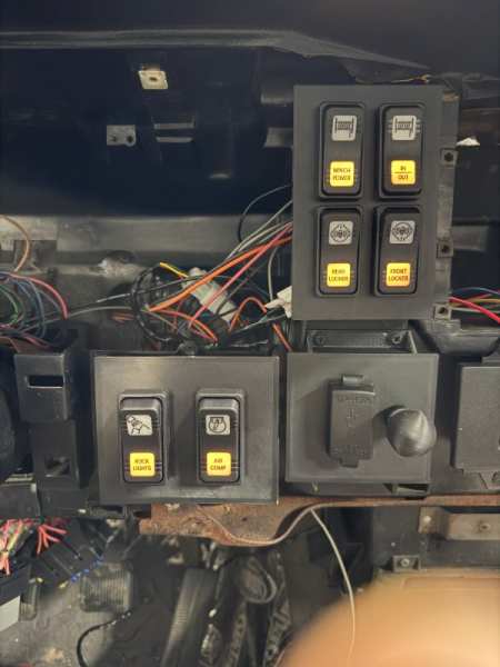
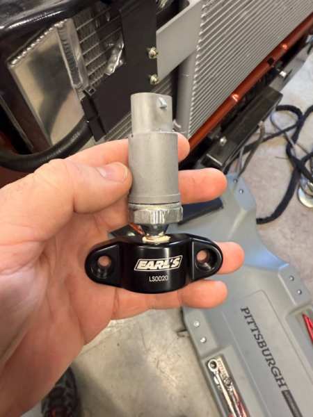
Huge amounts of progress. Engine is running excellent. Was able to move under its own power finally. Need to plumb the brakes still but that should be quite straightforward. Interior electrical is about 90% finished now. All my gauges are working perfectly. Once I finish this project I’ll post up details of how things are setup.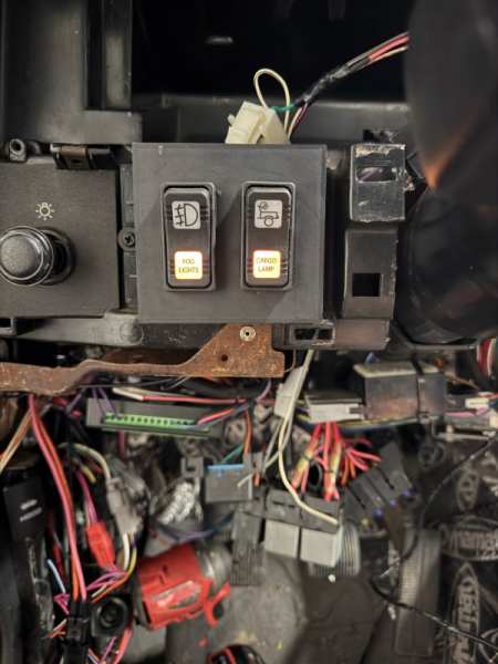
-
factory style fog lights
ghetdjc320 replied to BEEDOSAUCE's topic in MJ Tech: Modification and Repairs
You can test your switch for continuity to rule that out. Then test the power coming to the switch from the headlight switch as outlined above. -
Project “Tomahawk”
ghetdjc320 replied to ghetdjc320's topic in MJ Hardcore Tech: Epic Journeys to Greatness
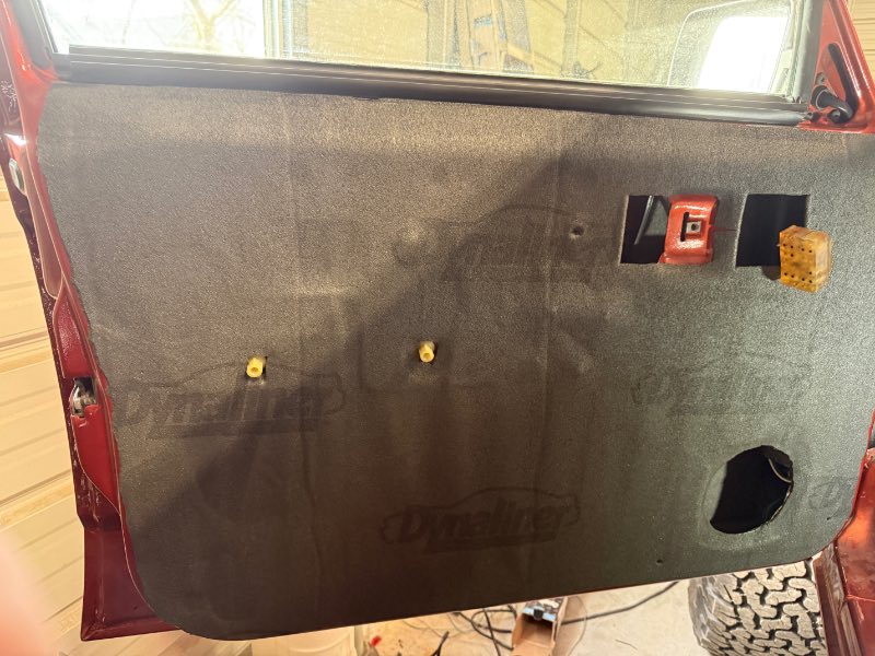
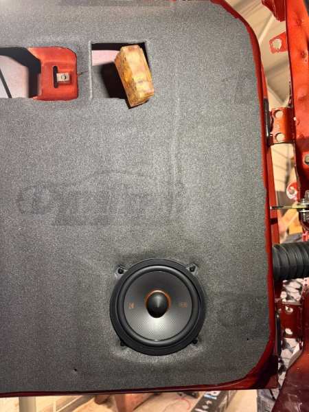
I Partly. Also a good thermal barrier and dampener. The inside of the doors and around the speaker have been completely dynamated. The dynaliner is a 1/8” closed cell barrier just used behind the door panel. The door panels themselves are 3/16” birch with a foam layer followed by the vinyl. They are quiet as a Mercedes -
Project “Tomahawk”
ghetdjc320 replied to ghetdjc320's topic in MJ Hardcore Tech: Epic Journeys to Greatness
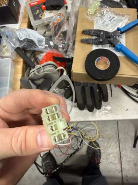
Some update pics: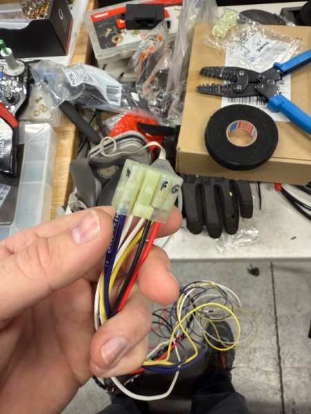
-
Rear TJ Rubicon Dana44 swap into MJ
ghetdjc320 replied to comanche_chris's topic in MJ Tech: Modification and Repairs
Explorer and KJ cables are longer -
Rear TJ Rubicon Dana44 swap into MJ
ghetdjc320 replied to comanche_chris's topic in MJ Tech: Modification and Repairs
The disk brake parking brake levers are similar between ZJ, TJ/LJ and Explorers. You can use pretty much any of those cables, just get the right length and be mindful of different length for right/left (nothing wrong with getting a pair of left or rights if the length is what you need). The length description is typically posted on rock auto. LJ disk parking brake cables may be a good option?? KJ are around 70" IIRC but that extra length allows some rerouting if you prefer. -
DirtBound Offroad going out of business?
ghetdjc320 replied to jeff351's topic in MJ Tech: Modification and Repairs
I ordered my hitch and DIY bumper around thanksgiving and received it mid January. From what I gather, he's outsourcing operations. -
Project “Tomahawk”
ghetdjc320 replied to ghetdjc320's topic in MJ Hardcore Tech: Epic Journeys to Greatness
Mostly running out of time . Aluminized works well if you keep it clean. I was going to tig up a 304 system but just don't have the time. this should last me several years and is honestly going to be a nice layout to model after when I eventually tig up a stainless setup . I've been down into the column that far before, but it's been some time back. Probably a couple of hours to carefully disassemble and get it repaired correctly. Going to use red Loctite and torque to spec. I also replaced the turn and wiper switches and installed a NOS cruise control turn signal/wiper lever. I removed the OE style cruise control connector and replaced it with a 4 pin Deatsch connector to connect to the LS PCM. -
Seat belts - what fits
ghetdjc320 replied to ghetdjc320's topic in MJ Tech: Modification and Repairs
build time is about 8 days so i'l post up when i get them -
Charcoal Canister and vent line parts
ghetdjc320 replied to J33ps's topic in MJ Tech: Modification and Repairs
Ive heard that DeLorean has replacements available. @Limeyjeeper used them iirc -
Project “Tomahawk”
ghetdjc320 replied to ghetdjc320's topic in MJ Hardcore Tech: Epic Journeys to Greatness
Another project I'm going to knock out: I noticed a bit of play in the steering column and discovered its the 4 external torx bolts that hold the tilt head onto the column. You can sort of get to two of them to tighten them but two remain inaccessible unless you remove the two pivot pins and the tilt head. Ordered up the remover tool and will pull those out to Loctite them and re-secure everything. Also had a bit of slop in the OE steering shaft u joint so i picked up a Borgeson HD unit to replace it. Will report back on how it all fits. -
Seat belts - what fits
ghetdjc320 replied to ghetdjc320's topic in MJ Tech: Modification and Repairs
Well, just got off the phone with seatbelt planet. They are based out of Oklahoma and were very responsive and happy to make a seat belt setup for a bucket seat Comanche. They had a SKU already but had not seen a bucket seat MJ before and only made belts for bench seat trucks. I remembered that @USN_JeepMJ had used them but had to make brackets to accommodate the buckle end. I spoke with a man named Steve and sent him some reference pictures of what the buckle ends look like for the buckets along with the sleeves and they are going to build them for me and make a new SKU available for bucket seat trucks. Hopefully we will have a nice bolt-in option now -
Seat belts - what fits
ghetdjc320 replied to ghetdjc320's topic in MJ Tech: Modification and Repairs
I believe these are a good option. Being from a 2dr they seem to have the right lengths and the bolt-on ends appear to be correct. Perhaps also add the above sleeves and this may be a bolt-in set. Perhaps I'll be the guinea pig and give them a shot. 1984-1996 Jeep Cherokee 2 Door, Bolt-In Ends -
Seat belts - what fits
ghetdjc320 replied to ghetdjc320's topic in MJ Tech: Modification and Repairs
I've come across these a few times. I believe it's the same as the MJ units. 1984-1996 Jeep Cherokee Buckle Sleeve -
Project “Tomahawk”
ghetdjc320 replied to ghetdjc320's topic in MJ Hardcore Tech: Epic Journeys to Greatness
By all means! Planning on getting it fired up over the weekend. Then it's on to finishing up the brakes and cab wiring with is about 80 percent complete so far. I think I think the end is finally in sight. Curious to see what curve ball this thing throws at me next -
Project “Tomahawk”
ghetdjc320 replied to ghetdjc320's topic in MJ Hardcore Tech: Epic Journeys to Greatness
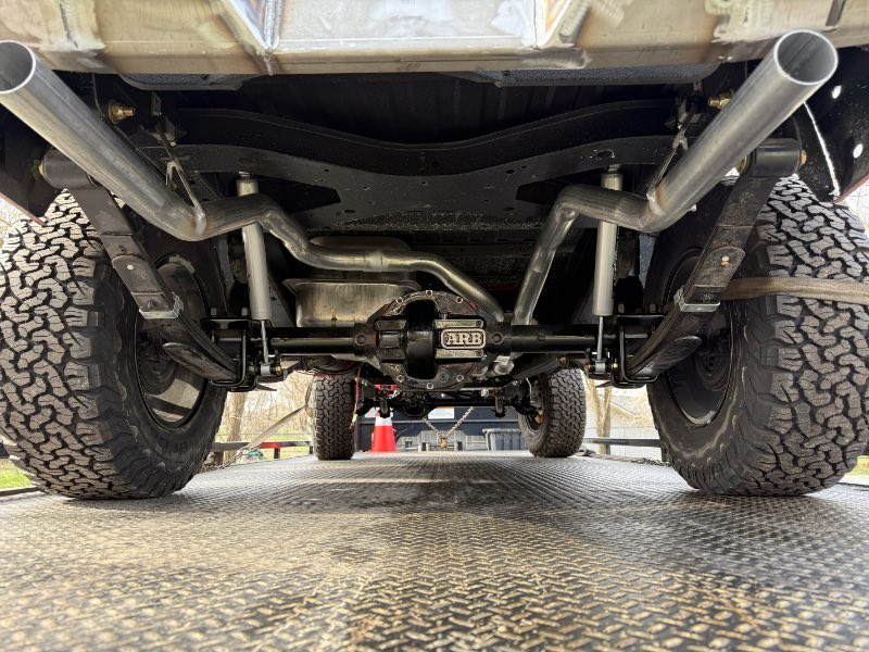
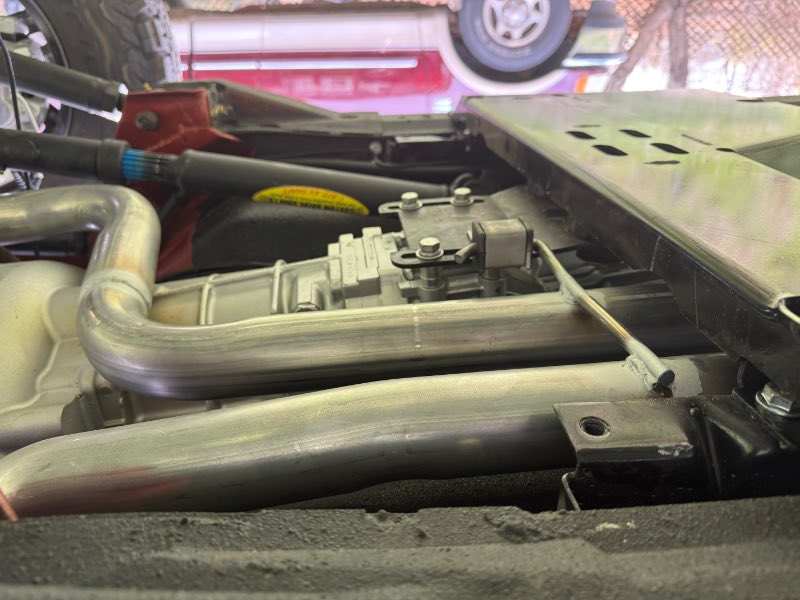
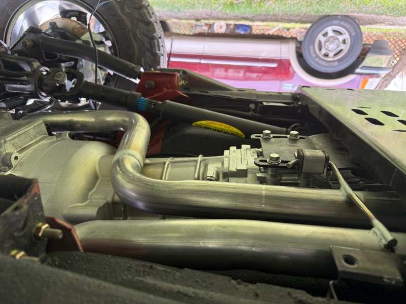
And here we have it, true dual exhaust on an MJ. Once I get the engine running and the truck driving, I’ll have the exhaust shop tuck the tips up a bit closer to the bumper and trim them flush. Also would like to get some extra clearance near the pumpkin. Definitely some challenges working with an LCG engine swapped rig. But overall very satisfied with the results. Looking forward to hearing it for the first time, hopefully over the weekend.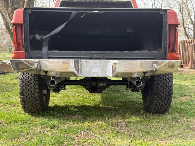
-
Interesting, thanks for the pic! A little different from the oem but looks like a good design
-
I’m going to cross post this content for reference. The Crown 97+ seals seem to be a good option:
-
Seat belts - what fits
ghetdjc320 replied to ghetdjc320's topic in MJ Tech: Modification and Repairs
IIRC, it has something to do with the length of the webbing while in the retracted position. I was thinking the 4dr XJ belts mount higher up on the pillar and ultimately have a shorter overall length than the 2dr ones. I'm wondering what source though offers new belts that fit and function as they should.