
ghetdjc320
-
Posts
5079 -
Joined
-
Last visited
-
Days Won
1
Content Type
Profiles
Forums
Gallery
Everything posted by ghetdjc320
-

Project “Tomahawk”
ghetdjc320 replied to ghetdjc320's topic in MJ Hardcore Tech: Epic Journeys to Greatness
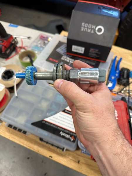
Tidbit of tech info for posterity: the Tom woods np242 sye kit shift rail plug thread size is 5/8-18 and approx 1/2” long. This is also a common automotive oil pan plug size. This also fits the switch port on the NP242. -
Project “Tomahawk”
ghetdjc320 replied to ghetdjc320's topic in MJ Hardcore Tech: Epic Journeys to Greatness
Added the correct wiring for pcm control of the ac system. Should be a factory like integration now utilizing the GM pressure sensor. The trinary switch has been eliminated. Will still be using the oe freeze switch for the evaporator core as well. Also swapped over the correct 38 tooth Speedo drive gear so the pcm will read the correct speed which is relayed through the Dakota digital 128k ppm sender. The 4k ppm output from the GM PCM will be sampled and up converted to 8k to run the 120mph Jeep speedo through a Dakota digital signal processor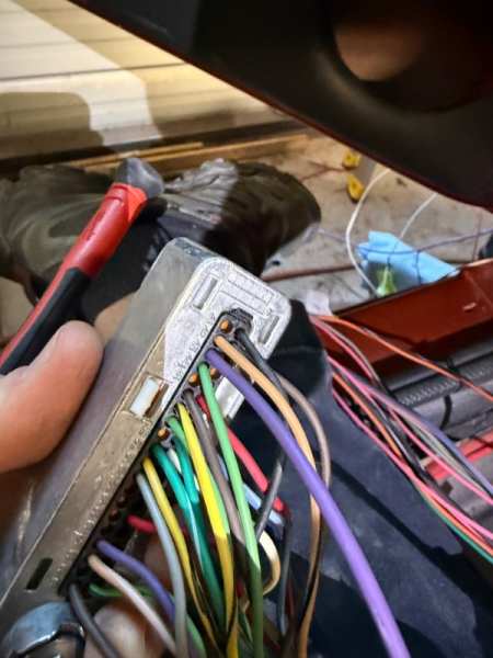
-
Project “Tomahawk”
ghetdjc320 replied to ghetdjc320's topic in MJ Hardcore Tech: Epic Journeys to Greatness
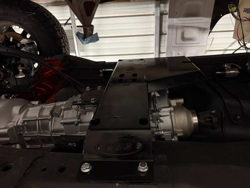
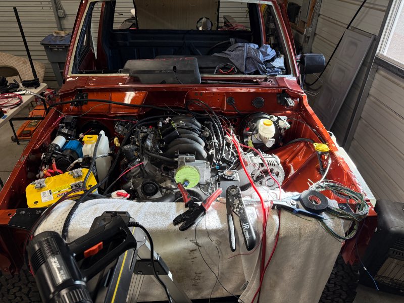
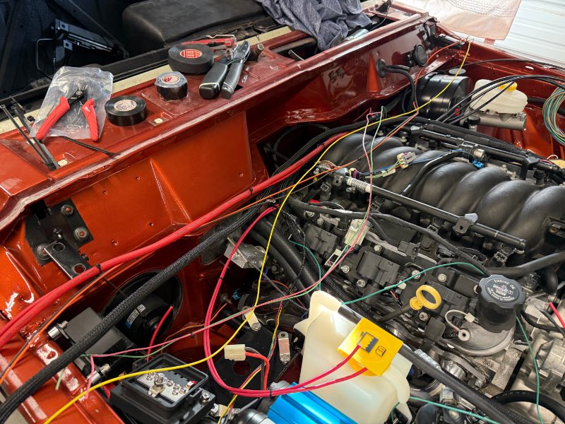
Under hood wiring is now complete with all circuit installed and tested. Everything works excellent. onto the interior side now. Also with the unneeded tabs removed from the np242, I was able to keep the SFR tcase skid/crossmember tucked up neatly. There is exactly a 1/4” gap between them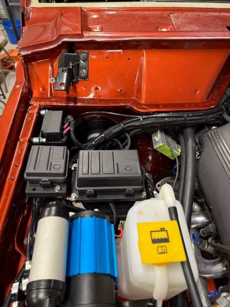
-
Project “Tomahawk”
ghetdjc320 replied to ghetdjc320's topic in MJ Hardcore Tech: Epic Journeys to Greatness
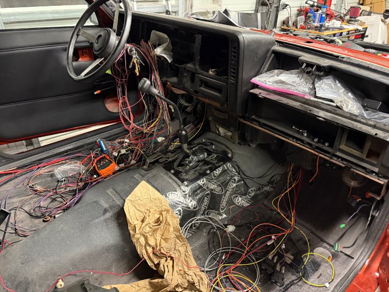
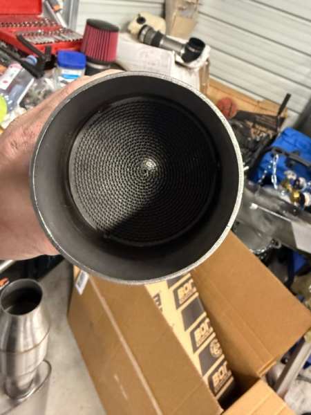
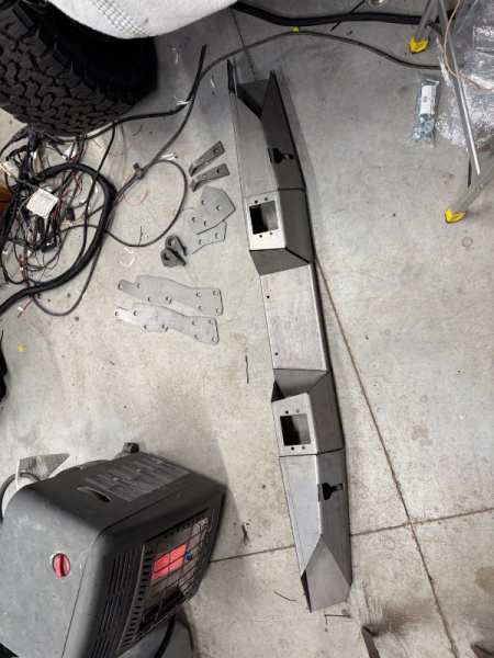
Pure wiring madness. Took a break from electrical and started assembly of the rear bumper. I wanted the diy version as I wanted to do a few mods to it for a cleaner look. Here is a glimpse of my exhaust system as well. Lots of meticulous parts selection and test fitting. The cats are stainless spun vs ceramic core.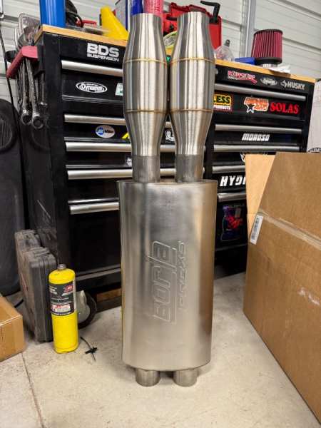
-
The dog would probably love it
-
Project: Slippery Slope – a ’91 MJ runner
ghetdjc320 replied to Gjeep's topic in Member Projects: Your Comanches
Looking great! -
Project “Tomahawk”
ghetdjc320 replied to ghetdjc320's topic in MJ Hardcore Tech: Epic Journeys to Greatness
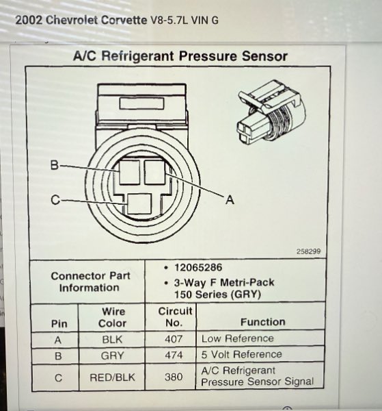
So, I've decided to do a little writeup on the Jeep A/C system and how it pertains to an LS swap, particularly a C5 corvette LS1/6 swap. For a little back history, The Jeep HVAC control deck sends a signal to the ecu known as A/C select. The Jeep ECU then receives a signal on another terminal that is routed through the A/C pressure switch and the evaporator thermal sensor known as A/C request. The ECU may have some logic processors that will account for such things as engine coolant temp or other criteria before it triggers the A/C clutch relay, but it doesn't account for much. Now onto the LS side of things. The 411 PCM had many different programs that could be flashed to it. The C5 corvette programming had two versions of AC control. One was called "manual" and the other "automatic". This has to do with the climate controls or HVAC deck. For the version that had "automatic" controls, there is a serial data line that goes into the PCM that contains some of the HVAC control deck logic functions. The "manual" AC systems had an "A/C request" signal that goes to pin 17 on the red connector. This was a 12v- or ground connection. It is noteworthy that this is not the same programming as the F body cars or any of the trucks as those mostly had a 12v+ signal on this pin. It can get to be annoying and confusing when people refer to "ls" engines and "411" PCMs as if they were all the same for Gen 3 engines. Most references I see from wiring harness manufacturers and aftermarket PCM tuners are using and referring to f body or Camaro programming on the PCM. Back to the C5 corvette programming on the 411 PCM; In regard to the AC system, the corvette uses a 5v A/C pressure sensor with a female M10 sensor port that goes on the high-pressure side of the system (between the drier and expansion valve high side for most Jeep applications). The GM PCM receives the ac request ground signal, checks the ac pressure signal and integrates all of the logic algorithms such as engine coolant temp, throttle position, RPM, engine load (MAP), and vehicle speed to determine when the compressor will be triggered and when fans 1 and 2 will run (on a Jeep triple fan setup, Novak recommends running the driver's side and center radiator fan as "fan 1" and the passenger side radiator fan as "fan 2"). The PCM also receives confirmation that the A/C clutch has received an activation signal by sensing voltage on pin 18. I've attached a diagram below of the way this is all wired. I have thoroughly subscribed to the guidance Novak has provided to "make the engine think it's still in its original application" to the extent possible. I'll post up how I will be wiring my system shortly but i'll be following the GM layout as much as practically possible. Note the diagrams for the ac system and the connector view for the ac pressure sensor Air Conditioning - Compressor Circuit 2002 C5.pdf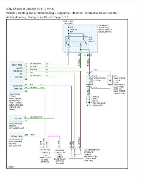
-
It is the 3/4 gear synchros that are the problem in most newer kits. Grab an extra pair of 1/2 synchronizers and use those on 3/4. You could probably get away with reusing the 3/4 synchros if they are in good shape. Pay attention not just to the synchro teeth but also to the cone surface on the back side. That is the portion that provides the needed friction for proper spin up and gear engagement. Here is the link to the proper earlier ax15 3/4 synchronizers: AX15 R151 1-2 Synchro Ring TOY-14C - AX5 5 Speed Jeep Repair Part
-
I would add on an extra pair of synchros as well as the ones they sent had the wrong tooth design. I don’t recall if it was the 3/4 or 1/2 that were incorrect. I believe it was the 3/4. I’ll check my notes
-
Checkout Allstate gear. They use all nachi bearings, and synchroking synchronizers. They also offer most all small parts including the 5th gear update kit. Depending on the year of you ax15, you’re likely going to need a different synchro for 3/4 than what comes in most kits. I posted up some of the synchro differences and pictures in my build thread (pages 24-25) along with some upgrades that can be done at the same time. I’m not sure if I noted this or not in my posts but I ended up removing the “new style” synchro with different tooth design and replaced it with the correct tooth design which should perfectly match the synchro hubs.
-
Project “Tomahawk”
ghetdjc320 replied to ghetdjc320's topic in MJ Hardcore Tech: Epic Journeys to Greatness
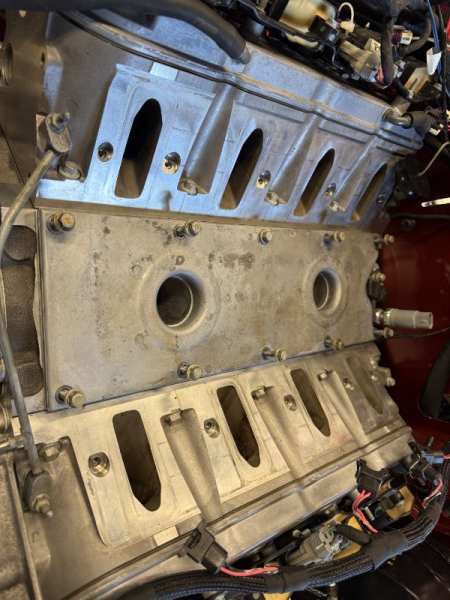
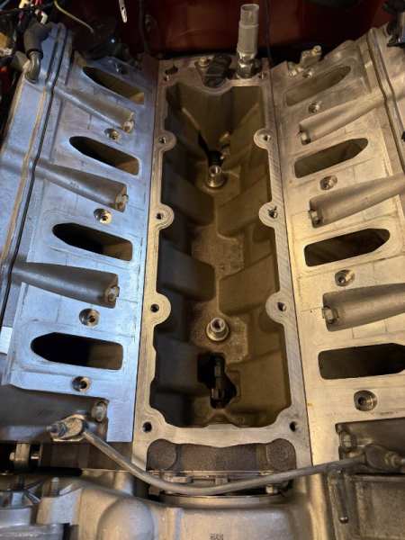
Following up on the TSB posted before, it appears that this TSB came out in 2003 and the 2004 and later valley covers remedied this by raising the little flange on the top of the valley cover a bit higher to prevent water intrusion. I just check my new valley cover and sure enough it has a more pronounced "ridge" than the original. -
Project “Tomahawk”
ghetdjc320 replied to ghetdjc320's topic in MJ Hardcore Tech: Epic Journeys to Greatness
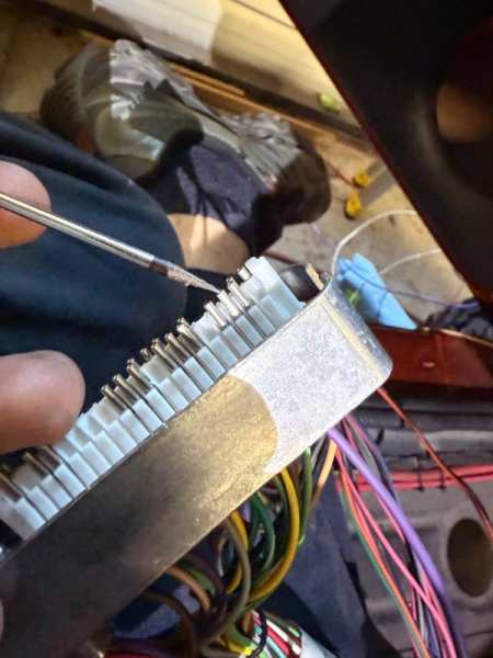
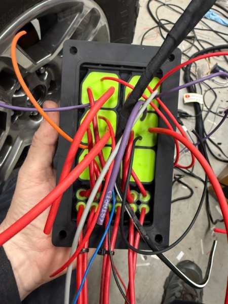
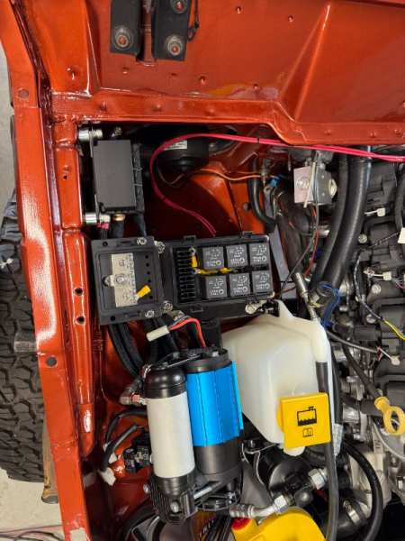
Coming along…. I am really liking how clean the wiring is when routing it all behind the engine. This has taken a painstaking amount of planning and routing, making sure no circuits are missed. There are many connections that need to be added to the painless harness but ultimately it seems to be a good solution for replacing all the factory wiring.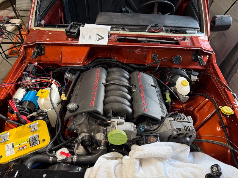
-
Project “Tomahawk”
ghetdjc320 replied to ghetdjc320's topic in MJ Hardcore Tech: Epic Journeys to Greatness
Sounds good, that’s what I got. Apparently on the corvette programming, the ac request on pin 17 is a ground request. Painless and psi both advised using a 12+ but that appears to only apply to truck and f body programming. -
Project “Tomahawk”
ghetdjc320 replied to ghetdjc320's topic in MJ Hardcore Tech: Epic Journeys to Greatness
Good to know. Do you happen to recall what pin you sent the AC request to on the pcm? For vss, I’m using a Dakota digital 128k sender that I modified to fit the Jeep sender. So the ecu will see 128k ppm just like the stock t56 put out. Then using the Speedo output from the pcm which is supposed to be 8k ppm just like stock Jeep. I have the Dakota digital box if needed to convert frequencies but I’m hoping it won’t be used. -
Project “Tomahawk”
ghetdjc320 replied to ghetdjc320's topic in MJ Hardcore Tech: Epic Journeys to Greatness
Here is the TSB referenced above: https://www.corvetteforum.com/forums/attachments/c5-general-103/what-would-you-pay-for-this-c5-3680571/02-06-04-023a-47899884d1436760407 -
Project “Tomahawk”
ghetdjc320 replied to ghetdjc320's topic in MJ Hardcore Tech: Epic Journeys to Greatness
That’s a good point! I’ll add some good sealer there. Couple of questions I wanted to ask you also: What did you end up doing for ac idle up signal? And did the 411 pcm tach output wire work for your tachometer signal without any other mods or was a pull up resistor required? TIA -
Glad to see those caliper mounts welded into place
-
Project “Tomahawk”
ghetdjc320 replied to ghetdjc320's topic in MJ Hardcore Tech: Epic Journeys to Greatness
So after having spoken with painless and seen other posts from psi conversions, they are both saying to provide pin 17 on the red ecu connector with the ac clutch signal for idle up. According to the factory diagrams for the corvette, that will need to be a ground signal not a 12v + signal like the ls1 f body vehicles had. Also will be adding an rpm cutoff logic board. The 12v coming from the ac control deck will go to the logic board which will be N/O. The logic board will close the switch below 500 or so RPM and above 4000 RPM. This 12v wire will then continue to one side of a relay trigger. The ground signal will go through the trinary pressure switch, then splice into two and feed the ground side of the relay trigger along with pin 17 on the red 411 ecu connector. The second trigger output from the trinary pressure switch will provide a second ground source for the fan relays. With the AC on, all the fan relays will activate. -
Project “Tomahawk”
ghetdjc320 replied to ghetdjc320's topic in MJ Hardcore Tech: Epic Journeys to Greatness
-
Project “Tomahawk”
ghetdjc320 replied to ghetdjc320's topic in MJ Hardcore Tech: Epic Journeys to Greatness
Lines running from each item to the breather -
Project “Tomahawk”
ghetdjc320 replied to ghetdjc320's topic in MJ Hardcore Tech: Epic Journeys to Greatness
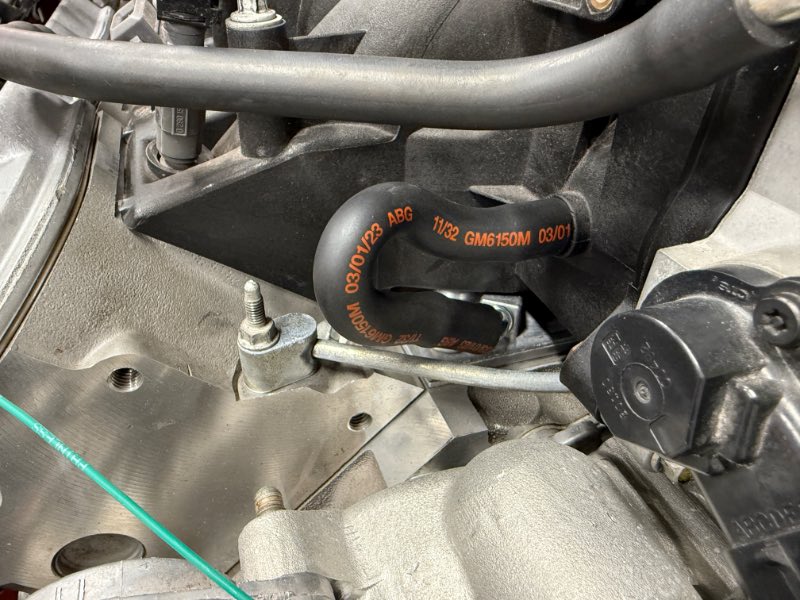
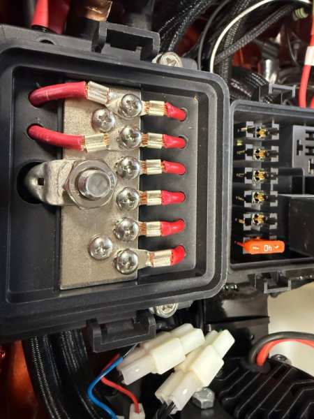
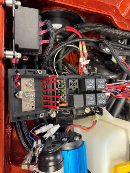
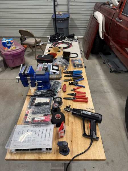
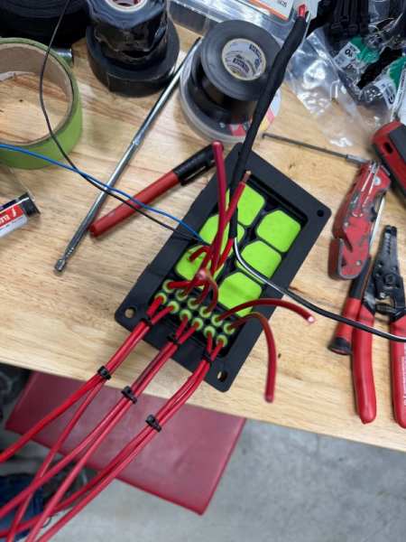
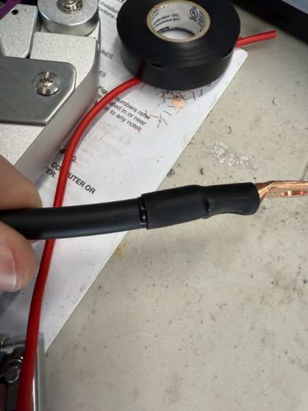
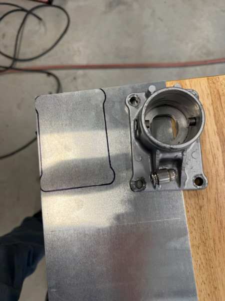
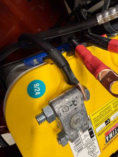
Mountains of electrical and final fitting of mechanical components coming together little by little. Tcase linkage is finished. Also finished assembly of the transmission shifter. I made a thin aluminum plate as a baffle like the nv3550 had in later years to prevent oil slosh from entering the new vent I installed. The ARB breather is now mounted and will vent both axles, transmission and transfer case. Finished up the winch solenoid wiring and got everything routed and terminated. Used 2awg welding cable and copper lugs then installed marine grade heat shrink tubing that is adhesive lined to keeps things sealed. Routing lines, cables and hoses is very time consuming but well worth the effort. I’m also ditching the arb relay and fuse and integrating them into my fuse/relay box and power distribution. The winch control switch wiring, arb harness, and all engine wiring is routing through the old renix ecu firewall plug. The painless bulkhead connector is handling lighting, wipers, horn, oil/water sensors and a few accessories such as the rock lights. Didn’t get many pictures taken today.
-
Well I decided to go with two high side ports, one at the compressor and one at the expansion valve. That way I can more easily diagnose a future AC issue. For the low side, I will be installing it on the expansion valve suction side. Should make servicing very simple with easy access. The 1990 AC system uses all standard o ring fittings in sizes 6, 8 and 10.
-
So I’m designing all new AC hoses and lines for my engine swap. Any thoughts on the ideal location for the high and low side service ports? I was liking the idea of installing them near the expansion valve to make them easy to access but not sure if that is an ideal location for taking readings. My ac compressor is a low mount block hugger setup so although I could technically put the fitting by the compressor, they will be tough to access. I mounted my dryer on a bracket near the battery. for my evaporator core, I’m using a newer plate a fin style along with the 91-92 MJ expansion valve for R134.
-
Project “Tomahawk”
ghetdjc320 replied to ghetdjc320's topic in MJ Hardcore Tech: Epic Journeys to Greatness
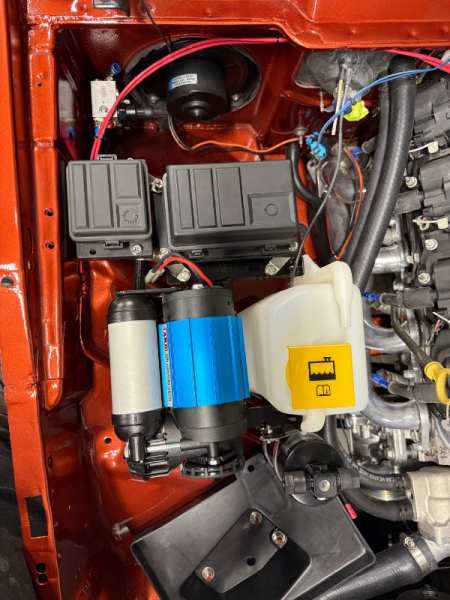
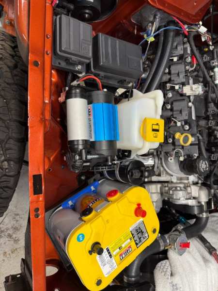
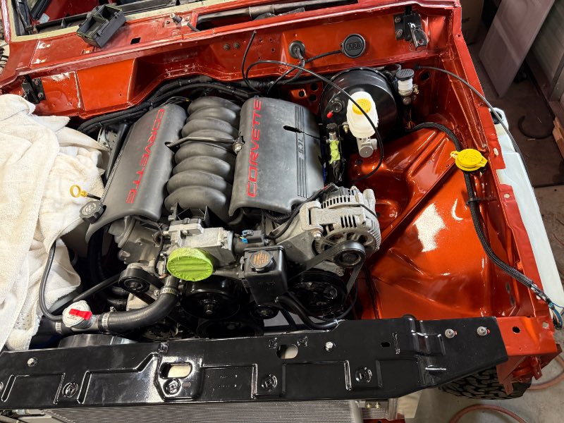
That was just a test fit. Took a lot of tweaking to get that bracket configured for all the accessories. It now holds the radiator bottle, compressor, ac dryer and relay/fuse box -
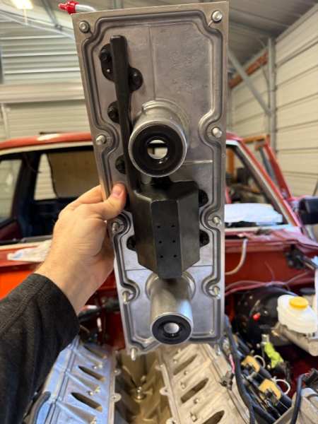
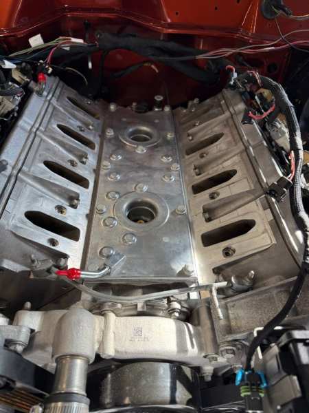
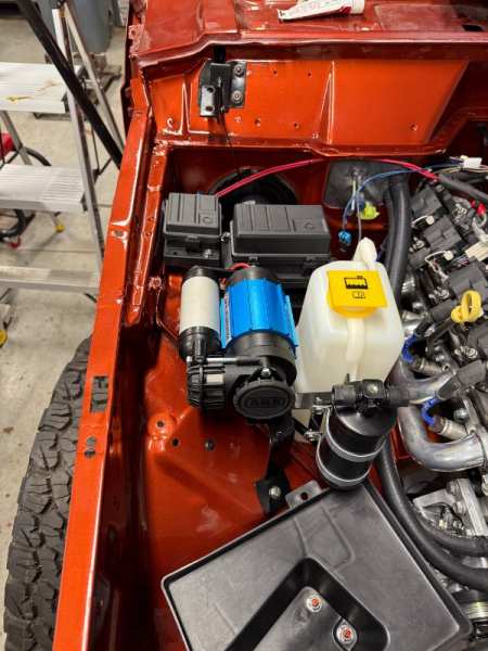
Project “Tomahawk”
ghetdjc320 replied to ghetdjc320's topic in MJ Hardcore Tech: Epic Journeys to Greatness
Mounting accessories. This process is tedious but I’m liking this layout. Also swapped to the 04 LS6 spec PCV valley cover and eliminated all the older style system. This will keep the intake much cleaner.