


Minuit
-
Posts
5139 -
Joined
-
Last visited
-
Days Won
13
Content Type
Profiles
Forums
Gallery
Everything posted by Minuit
-
The board is probably either screwed into the housing or held in by some type of plastic clips if I had to guess. But verify the circuit in the truck before looking harder at the ECU. Not saying it's NOT the problem, it's just the least likely cause of it by far. That looks to be a plated through hole board, which makes it somewhat less prone to bad solder joints. Just be glad it isn't made by the same people who made the factory radios for these trucks.
-
Get the electrical manual for your year and trace the fuel pump relay trigger circuit back to the ECU. You may have a bad connection or broken wire somewhere.
-
To test that on the bench you would need to essentially recreate the conditions under which it would be installed in the vehicle and you would need a fair amount of test equipment and more importantly, the knowledge to perform the tests. Any broken solder joints on the back side of the board? What makes you think the ECU is bad? That is typically the very last thing you suspect in a vehicle that is not running properly, after everything else involved with the issue has been tested good.
-
I will neither confirm nor deny that you can get one of those little forklifts stuck on a flat concrete floor. This was my little helper for the couple of weeks before I had my danger privileges revoked. Maybe a little too big for the job I was doing, but hey.
-
I've been following the Harry's Garage channel on Youtube for a while. Older British guy with very expensive taste in cars, mostly classic Lamborghinis and so on. He actually uses them though. So imagine my surprise when a very nicely sorted '88 Wagoneer shows up on his channel. Turns out he really likes them. Highlights include drifting around your typical idea of a classy British estate.
-
As for qualifications, I'm not an EE but I did complete the early parts of an EE degree as part of my ME degree. Circuit analysis I and II, lab equipment (that started a long and expensive fascination with vintage test gear), a terrible class on control theory, some very basic digital logic, a 5 minute tutorial on soldering, that kind of thing. Or to put it another way, a lot of surface level knowledge that isn't terribly useful on its own. I learned a hell of a lot more once I actually started doing it. The Art of Electronics is the most frequently recommended electronics book I've seen. It's a university level textbook though, not sure if you're wanting to go that deep. Look at some reviews and the table of contents to see if it's what you're looking for. As for our level of understanding, I'd give it an 8 or 9. We know pretty well what's going on with it, but we are almost to the point now where we are almost out of "room" to make transistors smaller. If there is a way around that, that'll be the next big breakthrough I think. It's not quite like magnetism - the only thing that really stuck with me in my electromagnetism class from school is that "we really have no idea how the @#$% this works" - at least, not in a way that you could explain to a sophomore that doesn't already have a strong background in physics.
-
And if conditions are right, that "LED driver" could be as simple as a single resistor, the value of which would be calculated based on the LED's current and voltage requirements.
-
Geez guy, way to make us all feel inadequate here
-
-
No argument from me For what it's worth, my MJs contain absolutely no LED-based lighting in any way. Because hot and inefficient is how it's SUPPOSED to be, damnit!
-
It's lower than it should be, but considering a Renix 4.0 in need of maintenance can have a pretty shifty idle I can believe it. Don't adjust it before you know for damn sure it's incorrect. Do you have a scan tool for your truck? Can you post a video of what your engine sounds like idling?
-
Damn forum ate a long and math-filled post that I was about ready to submit. The first result I found for a Jeep light bar claimed a 320W draw across 32 chips. I didn't care to look up the chips they used, but a typical LED chip is somewhere around 40% efficient. That means about 60% of the energy you put into it comes out as heat and 40% as light. That means that 40% efficient light bar is still dissipating 192 watts of heat. That's quite a bit, especially considering that each of these 32 chips is about the size of the head of a small nail, and the individual silicon tracks inside of the chip that make the magic happen are way smaller than that. We're talking microscopic here. Semiconductors can handle quite high temperatures, but you still want to keep them below a certain temperature. The larger your heat sink, the more ability it has to remove heat from the LED chips and dissipate it either through radiation or convection into the atmosphere. I'm sure there's a "make it look big, black, and mean" factor in there somewhere, but high power LEDs still dissipate a whole lot of heat and need fairly substantial heat sinks to be reliable. Sometimes, you'll even see forced-air cooling in LED lighting. It's somewhat common for LED replacement headlight bulbs to have fans in them. Still, it could be worse. We could be in the dark ages of incandescent lighting still. They're just heating elements we overdrive until they glow bright enough to light something up. Their efficiencies are in the low single digits. You can get over 150 lumens per watt out of a good LED, but maybe 16 lumens per watt out of the best incandescent bulb.
-
Crown is probably second best after a genuine Mopar unit. Still aftermarket, but a friend of a friend's dog once told me that Crown conforms to the Mopar specifications for some parts.
-
 This is the '90 FSM. The part about the spring doesn't specify a certain platform.
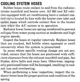
-
The FSM claims that the spring is indeed to prevent hose collapse under suction at mid to high RPM and tells you make sure it's there. I generally expect an aftermarket product to be, at the very best, as good as the old factory part it replaced and often worse in one way or another. Very rarely would my subjective experience tell me an aftermarket part has been better than factory. Based on that experience, I'm not sure I buy the "today's hoses are stiffer enough to not need a spring" argument. I'm very much ready to be proven wrong here. If anyone here has experience in the engineering or R&D department of a manufacturer of radiator hoses, please chime in. Until then, I will always recommend people put the spring in the new hose out of caution. I do not recall any of the aftermarket radiator hoses I put on my trucks being any thicker or stiffer (except for the old ones being hard from being old) than the factory parts.
-
Yes. As long as you bought the one for a gauge, not a light. Be prepared for it to read incorrectly if you bought an aftermarket one.
-
A/C whats the difference?
Minuit replied to ftpiercecracker1's topic in MJ Tech: Modification and Repairs
The pressure switch is a dual high-low cutoff switch. The receiver drier is on the high side of the system. The pressure switch changed in 1994 with the switch to R-134a. The receiver drier design is different between Renix and HO. If you try to put a newer model receiver drier in, I do not know if the lines will connect and I don't know if it'll even fit the truck. I would just buy a new receiver drier for your year. Yes, you can splice the plug if you want to try using the new design receiver drier. I can't tell you if it will fit. -
A/C whats the difference?
Minuit replied to ftpiercecracker1's topic in MJ Tech: Modification and Repairs
Charging by pressure is not ideal but it is probably what you will have to do. For reference, the '96 system takes 2 lbs of R-134a. The earlier systems took something like 44 oz of R-12. Parallel flow condensers and evaporators have lower capacity than the original style, so your charge amount probably end up somewhere between 1 and 2 lb. It's my opinion that the original R-12 pressure switch will probably be ok, since in normal operation its job is basically "yep, we have refrigerant present in the system. It is not dangerous to engage the clutch" and cycling is primarily done by the probe in the evaporator unless you have a leak and the system runs dry or something causes an excessively high pressure in the system. The pressure switch for a 94-96 XJ is calibrated for R-134a. The plug is different. I do not know if it will fit the earlier receiver-drier. I do not know if the later receiver-drier that goes with it will fit your truck. -
Not great, not terrible.
-
Look under that side brace before it's too late. Willing to put an unhealthy amount of money on there being more rust under there that you missed.
-
I've been in the logistics world for a while now and that still makes me giggle a little bit. Hope there's some cool stuff in there!
-
Fuse Block instead of Fusible Links
Minuit replied to Torq_Shep's topic in MJ Tech: Modification and Repairs
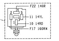
I think fusible links suck and should be done away with. That's not what my previous post was aimed at. My previous post was aimed at this: Fusible links are outdated, but replacing them with increasingly larger fuses until they don't blow anymore when you have not verified the circuit's integrity is not an acceptable way of doing it. You need to put together, at a bare minimum, a list of each fusible link protected circuit and the gauge of every single wire in that circuit. There are recognized standards for fuse sizing based on wire gauge, expected operating amps, and other factors. I looked at your build thread to get more details of what your problem was that led to the belief of a failed fusible link. This means that the relay is energized (if jumping either pin to 12V allows the fuel pump to run) but has an open circuit between the battery and terminal #1 which corresponds to pin 30 of the relay. The most likely suspect for this is fusible link 10-2 under normal circumstances, but with rodent damage anything is possible. You want to avoid messing with fusible links if you possibly can for now. That fusible link leads to a 10-pin connector on the right hand shock tower through a red 10-gauge wire at pin #5. According to the FSM, the part of the connector with rounded edges leads back to the battery via the starter relay and fusible link. The squared off side of the connector leads to a splice which branches to the fuel pump relay. I don't know off the top of my head what color this connector is or exactly what it looks like, but it should resemble the diagram. Unhook the battery. Multimeter on low range ohms (or continuity beeper if your meter has it), test between the 10-pin connector pin 5 "rounded" side and the positive battery terminal, and then test between the other side of that connector and terminal #1 of the fuel pump relay socket. Both sides should show near zero resistance, but one of those tests will probably reveal an open circuit. Report back what you find. If there is an open or high resistance between the + battery terminal and pin #5 of the "rounded" looking part of the connector as the diagram shows, suspect the fusible link but look for chewed wires in that area. If there is an open between the fuel pump relay socket and the "squared" half of that connector, suspect a chewed wire at some point between the connector and splice or between the splice and fuel pump relay socket pin #1. Clear as mud?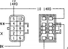
-
I would still put the spring in. I have little faith in an aftermarket replacement auto part to be more rigid than what it replaced, regardless of what the parts counter person says.
-
Fuse Block instead of Fusible Links
Minuit replied to Torq_Shep's topic in MJ Tech: Modification and Repairs
That's how a desirable, rapidly appreciating classic Jeep gets burned down. I hate to be abrasive, but this $#!& is important. The fact that you think that's an acceptable course of action tells me you need to slow your roll and do some more research. The way your post is worded tells me you don't know for sure if the fusible link is intact or not. Grab a meter and check across it for continuity. If the fusible link has continuity, you're looking in the wrong place anyway. Fusible links go open circuit, usually with some level of fanfare, when they blow. If it failed, it's more than likely because of a short to ground somewhere, but sometimes it's just good old fashioned corrosion. In any case, the correct thing to do is never "put in a bigger fuse and see what happens" Electrical work isn't done on feel. You need a wiring diagram and some basic electrical troubleshooting tools. Test light, multimeter, fused jumpers. Start checking every circuit that doesn't work like it should with a multimeter and/or test light. Check for power and ground at each accessory, find out what's missing. Go down the line until you arrive at your problem. If multiple things don't work, see if they share anything. The reason a Renix Jeep doesn't have an engine bay fuse box is this: our Jeeps were designed back in the early to mid 80s. Back then, a lot of what we consider standard practice for electrical system design wasn't a thing. Sealed connectors. Switching things with relays instead of 20 ft of wire carrying full current to a switch and back. Bus bars that aren't just "connect everything to the starter relay." Engine bay fuse boxes and power distribution centers. None of this stuff was standard fare back in the day, and the improvements made in this area in the 90s by Chrysler are one of the most important reasons why the 91 and newer Jeeps are just straight up better than the older ones. Look at the wiring design of 60s and 70s American cars and look back at your '89 Jeep. You'll see a lot of similarities. -
Fuse Block instead of Fusible Links
Minuit replied to Torq_Shep's topic in MJ Tech: Modification and Repairs
This is one of those subjects where no matter what kind of answer I give, someone will have a contrary, "better" answer. I tend not to touch these subjects as a result. It's about like asking what's the best oil to use or asking about putting platinum spark plugs in a 4.0. But I have plenty of time now, so here goes. The replacement fuses will be sized according to the wire gauges present in the individual circuit and the expected current draw in each one. There are a variety of standards for this, and I'll let you choose which one you decide to conform to. That being said, I believe it's very important that electrical work above all else conforms to a recognized standard and not just what Uncle Bubba Joe thinks looks like about the right size. So - I can't tell you what fuse to put in. You need to find that out yourself through study and measurement. But it's not something to be taken lightly. For the fuse to do its job and protect the truck in the event of a short they must be appropriately sized based primarily on the smallest wire gauge in the circuit and expected current draw. Additionally, these fuses must be located as close to the voltage source (the battery/alternator) as possible.