
Gojira94
-
Posts
677 -
Joined
-
Last visited
Content Type
Profiles
Forums
Gallery
Everything posted by Gojira94
-

Ho iac with renix harness
Gojira94 replied to ja_racing's topic in MJ Tech: Modification and Repairs
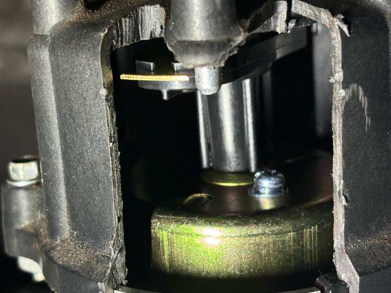
Mr. Thexton says yes. I wrestled with this for a while trying to answer the same question. In the pic below, the one on the left is from a '93 YJ. On the right, from an '89 XJ. Outer pin pair on both reads 50 Ohms. Inner pair on both reads 50 Ohms. Both move their pintles in the same direction in response to input from the tool. Note the different shape of the pintle caps, they're not interchangeable, as the idle air circuit passage shape is slightly different.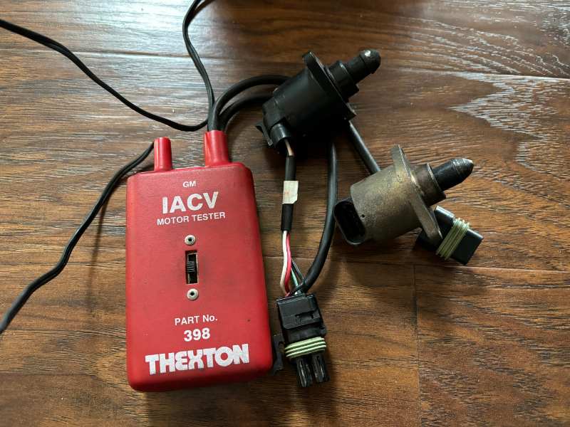
-
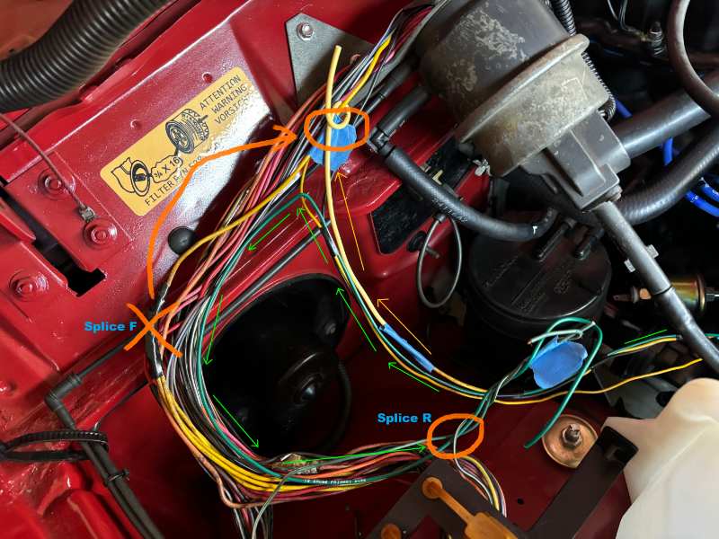
Rewinding back in time to my decision to relocate the coil and module- I wasn't sure if the connectors would reach. They don't. I'd hoped the wires for C213 & C214 would pull cleanly together out of the harness for extra slack to reach if not. They don't. So, what I'm doing is reorganizing it a bit to get C213 and C214 into one corrugated sheath and join the main part of the ECH between the cruise servo and blower motor. Yes, this is cutting into an intact survivor post-C101 Renix harness, but it would go back onto any other Renix, the only difference being extra length for C213 & C214. 1) Remove C213 pin C (18Ga, Grn w/trace) from splice R - extend green wire from C213 up and route back down and re-create the splice, so C213 & C214 can join the engine control harness at the same point. 2) Remove C213 pin A (14Ga Yel) from splice F - move further up, again so C213 & C214 can join the engine control harness at the same point.
-
Underneath, everything lines up well for O2, knock and CTS.
-
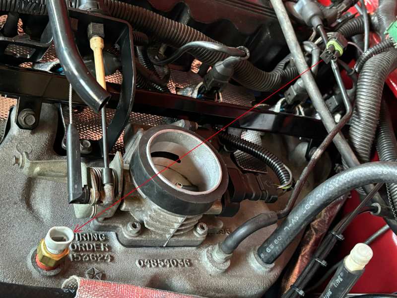
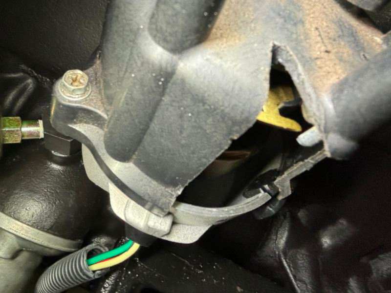
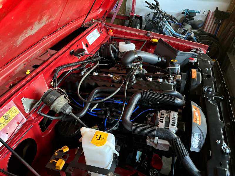
Sunday I started working the Engine Control Harness. Mine is Renix, from 89 or 90, so no C101 to contend with. Some changes are needed to make it work. Injector #3 connector won't reach straight up and down, as Renix didn't have the throttle bracket where it is on my setup. Tilting it works, but the rear arch of the throttle bracket needs significant clearancing to get the connector under it. TPS and IAC wires have to come out of the harness and move back about 4" to reach on an HO throttle body. All HO intake designs have the throttle body base exactly the same position, distance and elevation from the intake ports in the (HO) heads. I also have to make a connector adapter from the Renix IAT sensor connector to the updated GM IAT, relocated far away on the horseshoe intake. It'll run along the valve cover and shoot across between injectors 2 & 3. I haven't cleaned my throttle body and installed the TPS adapter yet.
-
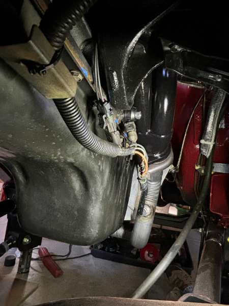
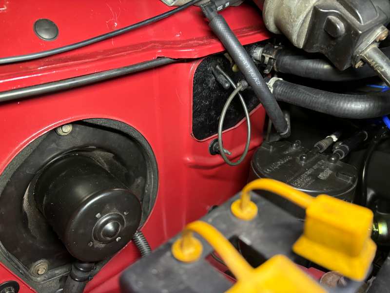
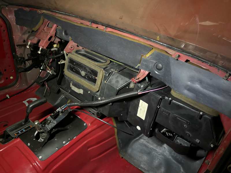
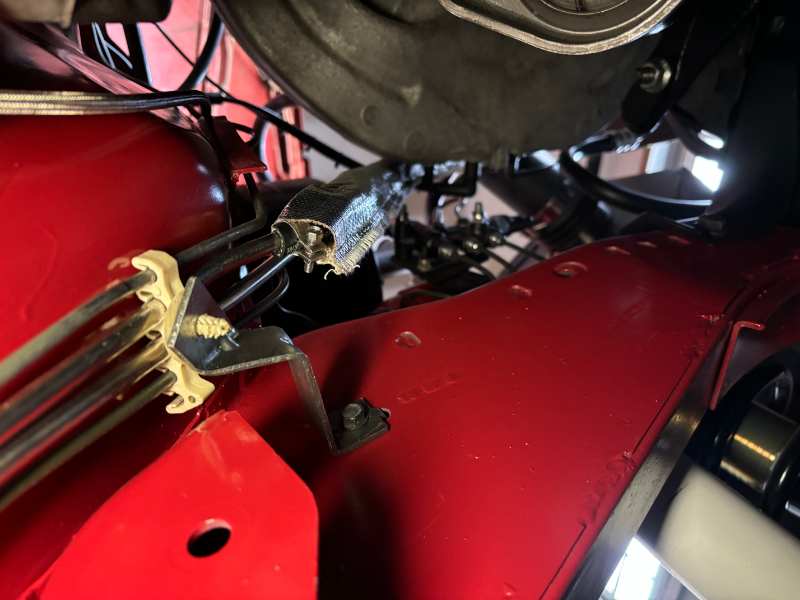
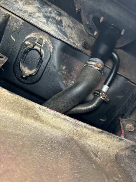
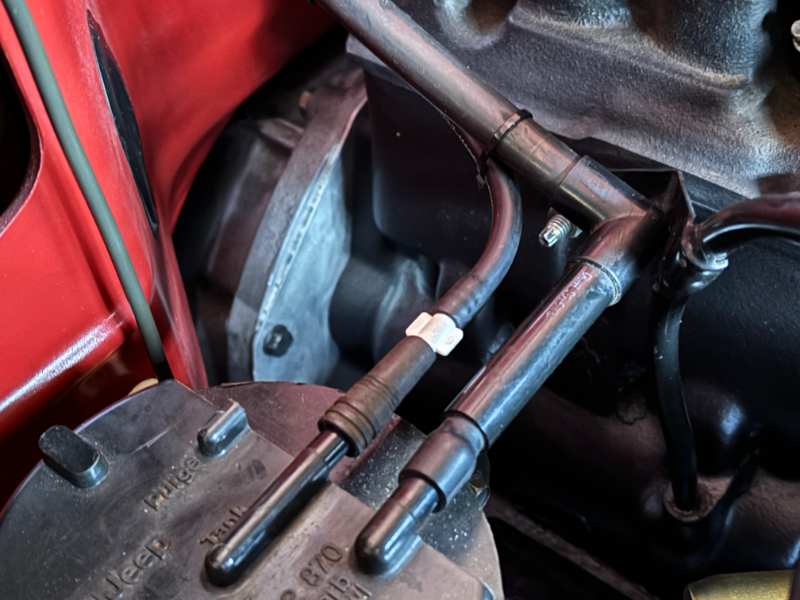
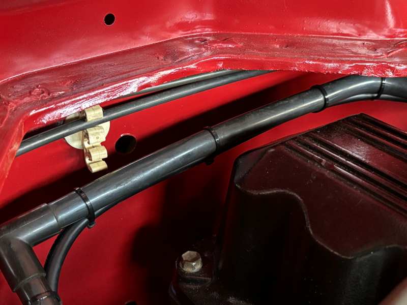
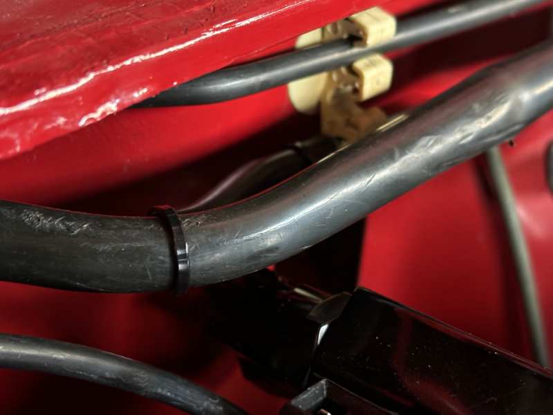
A couple things done on Saturday. Mostly the HVAC (in my case heater only) box. If you've ever taken one out, the studs probably came out of the housing when you backed off the nuts on the engine side. I screwed mine back in with some black RTV in each hole for extra grip. I also put a drop of black RTV at the base of the studs and slipped on a thin rubber washer (5/16" x 3/4") for each of the 5 studs. On the outside I applied the same washers under each nut so they're sealed as well as possible against water intrusion. My OCD in overdrive... I capped off the pink line to what would have been the heater control valve (long gone) and looped the black line to the check valve off the main vacuum source line (partially hidden behind the cruise vacuum dump hose).
-
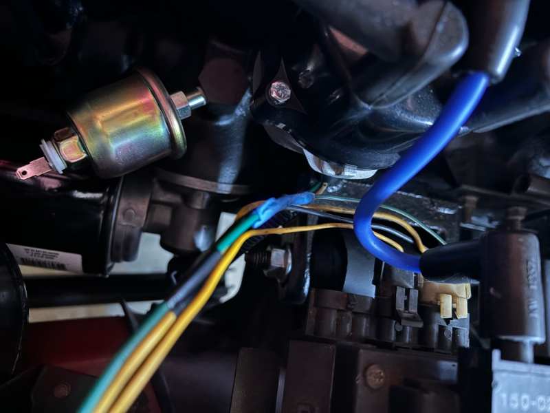
Thanks! I got the oil filter adapter from EBay. Every time an XJ would show up in my local salvage yard, the adapter would be gone the first half of the day it hit the yard. The EBay seller’s location was 35 minutes west of my house. That meant 2 things- he’s the guy that’s getting them all, and shipping would be fast lol. Price was $50, it came thoroughly cleaned and with the Fel-Pro gasket set for it. That’s only about $7-10 more than it would have cost me to get it myself, including entry fee plus the gasket set. The gold part is the 87-90 ‘Renix’ version of the oil pressure sending unit. That’s the one for gauge. The zinc coating gives it its color. The dummy light version is a switch, and smaller.
-
Need help with distributor stator wiring
Gojira94 replied to ja_racing's topic in MJ Tech: Modification and Repairs
-
The IAC will try to compensate if the throttle blade is a little too far closed at idle, or too much open. It can be defeated and not be able to open or close off enough air if the throttle stop is too far either way but that doesn't look like an issue, though stalling with throttle snapping closed could indicate it's a little too closed and the IAC can't increase bypass air quickly enough to keep it from stalling. I don't recall if the 1990 fuel rail has a Schrader valve. We used to tape a fuel pressure gauge to the windshield back in the day lol. I can see that being difficult with the hood on and shut far enough to drive safely. When you do the cap and rotor, cut a window on the old cap an rotate the engine to TDC on #1 and see where the rotor tip is. A complete write-up on that is in Cruiser54's Renix tips Index under the Modifications & Repairs sub-forum. Here's mine before and after:
-
When the throttle snaps shut at RPMs above 12-1500 or so, here's what happens: MAP drops to lowest possible (15-25kPA), engine braking starts. A LOT of timing advance is needed here due to the leaning of the mixture (see #2). flip side of MAP drop is vacuum increase, pulls hardest on FPR diaphragm, more than idle, part throttle or WOT). This equals lowest possible fuel pressure. unknown if Renix calibrations have a DFCO (Deceleration Fuel Cut-Off) or other similar routine, I'd guess there is some form of one to reduce fueling in decel. IAC opens more (pintle retracts) some number of extra steps to prevent stalling on closed throttle (TPS) with RPMs above ECU's target idle value in gear. Things to check related to drivability/ stalling will be if there is adequate fuel under decel, if timing is adequate and whether the IAC can provide the bypass air needed. Highly unlikely that the ECU-commanded extra spark advance will be changed, though it's possible that indexing of the distributor prevents commanded advance from being actually on the rotor tip (complete loss of spark at commanded degrees of advance). Other is vacuum leaks adding more air than commanded spark advance can burn with leaner than expected condition (inadequate fuel for condition). You're pretty sure vacuum leaks are out of the equation. Easiest thing to verify is fuel pressure at the rail. Distributor index check is obviously more effort. A check and cleaning of the IAC motor and housing never hurts. (you already did this)
-
Roger that, thanks for confirming. I tend to overthink things...
-
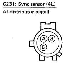
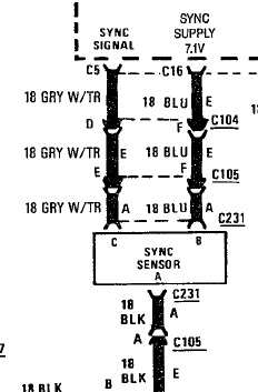
Need help with distributor stator wiring
Gojira94 replied to ja_racing's topic in MJ Tech: Modification and Repairs
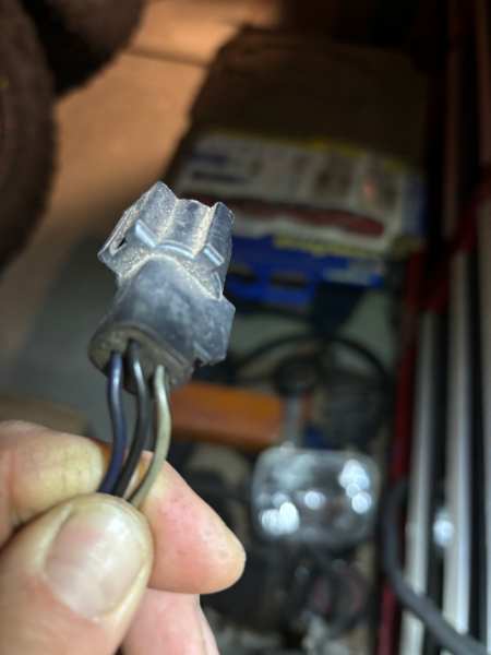
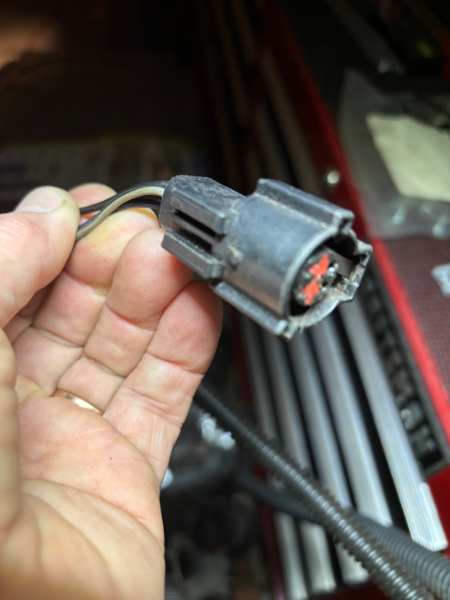
I can get that posted up for you around 6PM EST if no one else answers before then. -
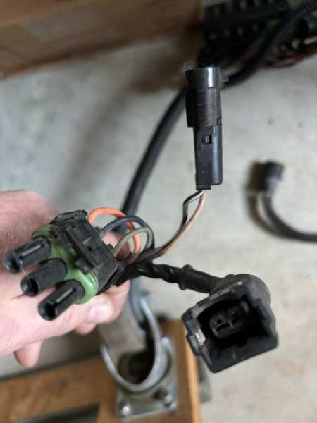
Hopefully this will help. O2, CTS & knock. O2 sensor connector is A) Orange - from O2 heater relay, B) Black - ground, C) Gray - sensor signal to ECU.
-
Planning out my home-brew fan setup, as my harness has no 'Heavy Duty Cooling Option' woven into it. My question isn't in the 'how' just 'how big' for relay and fuse. My fan is a TYC 620560, the 9 blade assembly for 97-01 XJ and I can't find real data on what its initial and running draws are. I see some variation in relay choices between 30, 40 and 30/40 amps. My initial thought is a 30/40 or 40 with a 30A inline fuse between 12V source and relay pin 30. I realize the initial draw is where the big spike is and I'm trying to set a reasonable expectation up front. Anyone got any information or experience with one of these fans?
-
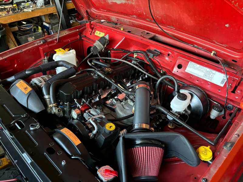
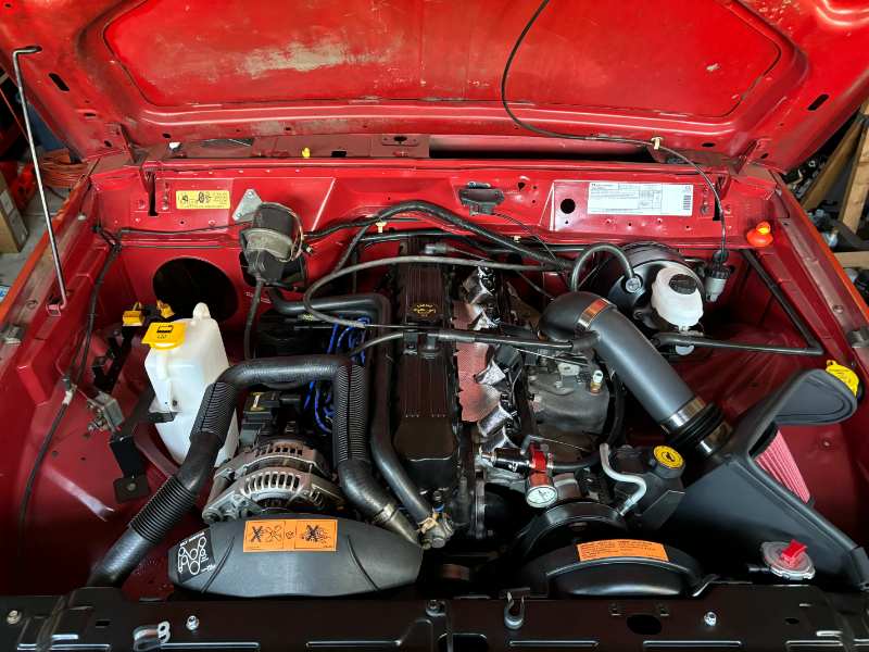
Ready for engine, injector and front lighting harnesses. Sourcing expansion tank to radiator line later today. A shout-out and big thank you to @boxyjeep for the awesome set of labels!
-
Hah. Just noticed you're in NC. Yeah, I finally got the last fitting I needed for my fuel system late yesterday, and my plug wires. Aggravating delays this week with the snow.
-
Yes.
-
Not sure for a Renix vehicle equipped with CAD and cruise. But it might work for all 3 systems with an additional T and feed line to the CAD added in.
-
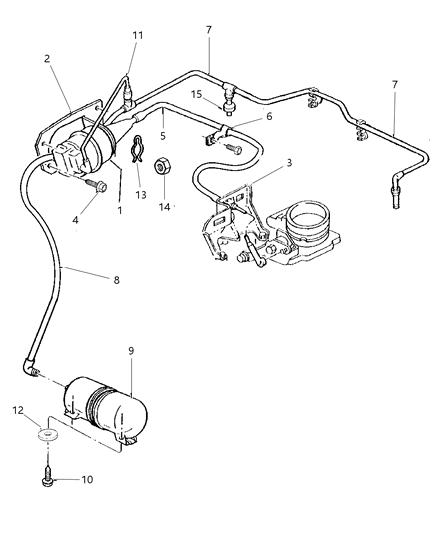
It looks like in 91 they just tried to simplify the setup with a single vacuum line for the tank and accessories fed by it, all the way through 2001 on the XJ. Electrical control of the servo changed from 5 wires to 4 to operate from VSS signal feedback in the ECU, but it was still vacuum modulated. It appears no check valve was fitted for the cruise servo vacuum source, just for the HVAC vacuum controls.
-
Interesting find in the boneyard- a 94 XJ showed up. I snagged a football reservoir with a single port. Just the one port for manifold vacuum. It uses a check valve at the HVAC. This XJ didn't have cruise so the tee where it would have connected was capped. I'd imagine in 94 it would have used a check valve there as well if cruise equipped (no, no check valve for cruise). This XJ had obviously been sitting in a tree row for a while, but it hissed when I disconnected the line from the reservoir. I like the simplicity of the setup, so I'm going to try it out as pulled, with no check valve at the cruise servo.
-
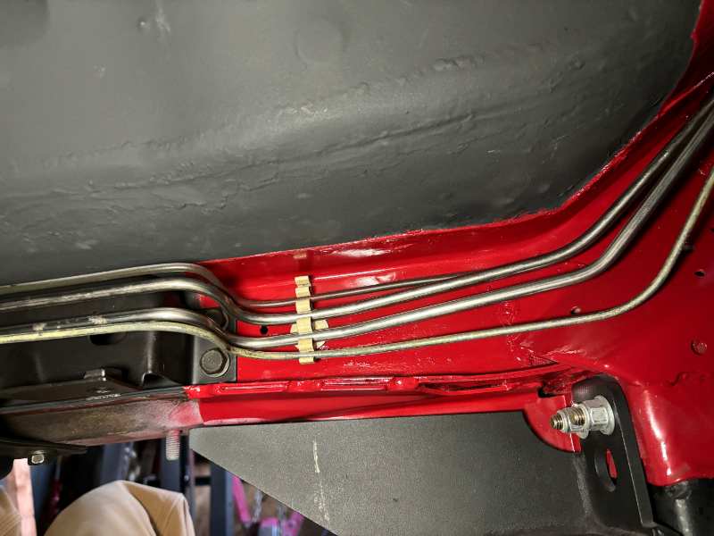
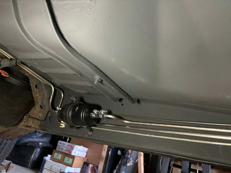
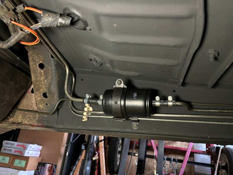
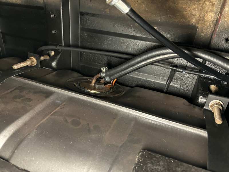
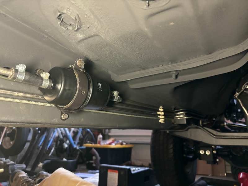
Fuel system complete, minus the inlet feed from hard line to rail. Waiting for one AN -8 to 5/16" barb fitting to show up.
-
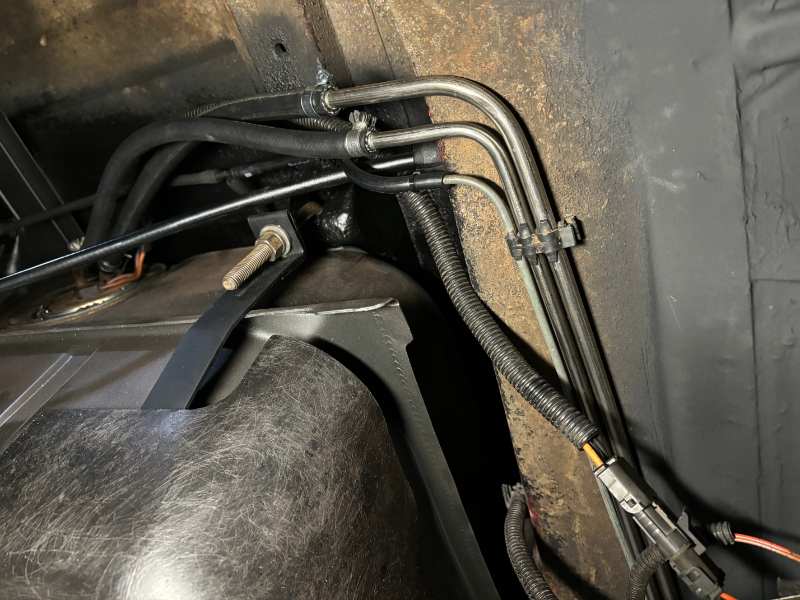
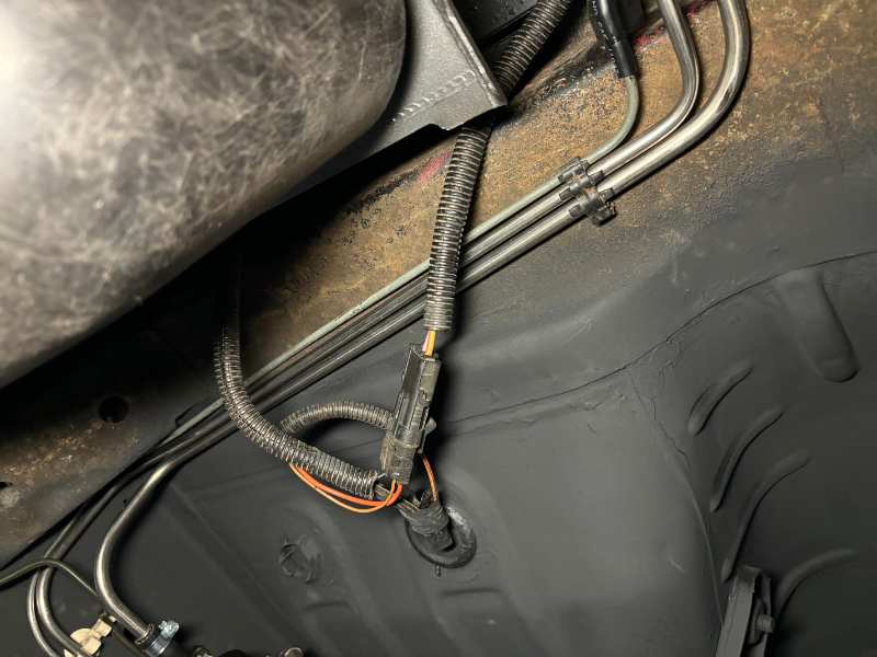
EVAP canister connections done.
-
MTS makes the hose assembly, part # JCCCH-8790, though I can’t find it listed on their site. Extreme Terrain sells it, also on EBay. JCCCH-8790
-
CCV fresh air hose. Other is the CCV metered orifice hose.
-
Well, it's an easy thing to swap, even with a completely assembled vehicle. I'm all over the map right now, pulling together vacuum lines, EVAP, fuel, etc. so I'm trying to sort things that could easily wait into a list.
-
Thanks all for the replies. I'll give the one I've got a go, if it doesn't seem adequate, I think the one-chamber football is what I'll look for.