cruiser54
-
Posts
9413 -
Joined
-
Last visited
-
Days Won
14
Content Type
Profiles
Forums
Gallery
Everything posted by cruiser54
-

Runs rich at idle
cruiser54 replied to speeding_infraction's topic in MJ Tech: Modification and Repairs
Why? At rest, Renix reads about .83 volts and the voltage climbs as the throttle is opened. The TRANS side of the TPS works opposite, like an HO. Is that what they spliced into? -
Runs rich at idle
cruiser54 replied to speeding_infraction's topic in MJ Tech: Modification and Repairs
Renix goes low to high -
OEM Crank sensor part number? ‘86 2.5L
cruiser54 replied to Vineyard86manch's topic in MJ Tech: Modification and Repairs
Yes. Check out your CPS. No parts cannon. Have you completed Tips 1 through 5 at my website yet? If not, do those right away. Easy even for a novice. Actually enlightening!!. -
OEM Crank sensor part number? ‘86 2.5L
cruiser54 replied to Vineyard86manch's topic in MJ Tech: Modification and Repairs
It's a crap shoot anymore with all the chicom junk out there. Is yours bad? Have you tested it? Modified it? CRUISER'S MOSTLY RENIX TIPS RENIX CPS TESTING AND ADJUSTING OCTOBER 30, 2015 SALAD 131 COMMENTS EDIT Renix CPSs have to put out a strong enough signal to the ECU so that it will provide spark. Most tests for the CPS suggest checking it for an ohms value. This is unreliable and can cause some wasted time and aggravation in your diagnosis of a no-start issue as the CPS will test good when in fact it is bad. The problem with the ohms test is you can have the correct amount of resistance through the CPS but it isn’t generating enough voltage to trigger the ECU to provide spark. Unplug the harness connector from the CPS. Using your voltmeter set on AC volts and probing both wires in the connector going to the CPS itself as shown in Figure 2 as Connector A, crank the engine over. It won’t start with the CPS disconnected. You should get a reading of .5 AC volts. If you are down in the .35 AC volts range or lower on your meter reading, you can have intermittent crank/no-start conditions from your Renix Jeep. Some NEW CPSs (from the big box parts stores) have registered only .2 AC volts while reading the proper resistance!! That’s a definite no-start condition. Best to buy your CPS from NAPA or the dealer. Sometimes on a manual transmission equipped Renix Jeep there is an accumulation of debris on the tip of the CPS. It’s worn off clutch material and since the CPS is a magnet, the metal sticks to the tip of the CPS causing a reduced voltage signal. You MAY get by with cleaning the tip of the CPS off. A little trick for increasing the output of your CPS is to drill out the upper mounting hole to 3/8″ from the stock 5/16″, or slot it so the CPS bracket rests on the bell housing when pushed down. Then, when mounting it, hold the CPS down as close to the flywheel as you can while tightening the bolts. Another little tip to save tons of aggravation is to stick a bit of electrical tape to your 11mm socket and then shove the bolt in after it. This reduces the chances of dropping that special bolt into the bell housing. -
Agree^^
-
Runs rich at idle
cruiser54 replied to speeding_infraction's topic in MJ Tech: Modification and Repairs
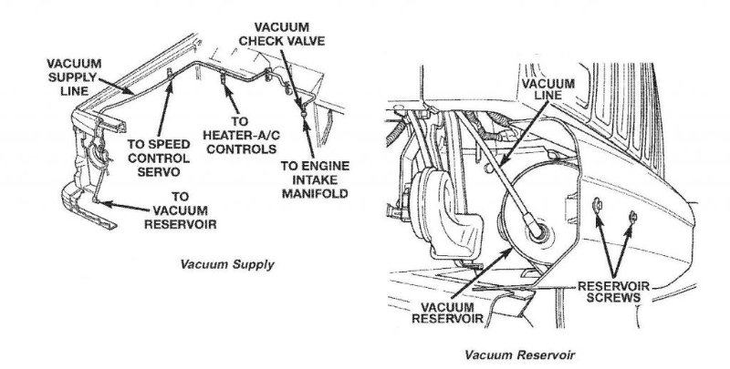
CRUISER'S MOSTLY RENIX TIPS RENIX VACUUM HARNESSES NOVEMBER 17, 2015 SALAD 29 COMMENTS EDIT The vacuum harness that attaches to the front of the valve cover and includes the grommet/fitting, and is called the front harness, is Napa part number BK 715-1367 or is a Dorman 46003. The vacuum harness that is closest to the air cleaner, EGR etc, and is called the rear harness, is Napa part number BK 715-1366 or is a Dorman 46004. The tube from the rear of the valve cover to the intake manifold is part number BK 715-1365 or Dorman 46005 and comes with the valve cover grommet. The Throttle Body to MAP hose is no longer available. Click HERE to access a fix for that. -
Runs rich at idle
cruiser54 replied to speeding_infraction's topic in MJ Tech: Modification and Repairs
No matter how it's wired, the sensors work opposite of each other. -
Runs rich at idle
cruiser54 replied to speeding_infraction's topic in MJ Tech: Modification and Repairs
Doesn't seem like it works well to me. Voltage to the ECU from one TPS goes up as the throttle opens and the voltage goes down on the other as the throttle opens. Tell me how that can work properly. Backwards. You need a Renix TPS adapted to the HO throttle body, or just get a Renix intake and throttle body. That HO intake and throttle body are not worth keeping. -
Runs rich at idle
cruiser54 replied to speeding_infraction's topic in MJ Tech: Modification and Repairs
Injectors: trevor.skankfootracing@gmail.com -
Runs rich at idle
cruiser54 replied to speeding_infraction's topic in MJ Tech: Modification and Repairs
HO and Renix TPSs work opposite of each other. The Renix system will not work with an HO TPS. -
Runs rich at idle
cruiser54 replied to speeding_infraction's topic in MJ Tech: Modification and Repairs
CRUISER'S MOSTLY RENIX TIPS THROTTLE BODY TO MAP SENSOR HOSE FIX JANUARY 23, 2016 CRUISER54 51 COMMENTS The Renix throttle bodies have a strange and failure prone connector on the side where the MAP supply originates and then runs up to the MAP sensor located on the firewall. This hose/pipe assembly is no longer available for purchase. The real kicker here is how critical this line is in supplying the correct vacuum signal to the MAP, the most relied upon sensor for the ECU to read regarding air/fuel ratio. Any cracks, melted spots, or loose rubber connectors can cause major starting and driveability issues. There’s a simple fix though. All that’s required is a 1/8” NPT tap, a new throttle body gasket ( Napa FPG 60742 ), a vacuum fitting (Napa 05703-B102), two vacuum elbows (Napa CRB2670), and a length of new plastic piping (Napa CRB2672). Remove the throttle body and take it to the workbench. Using an oiled tap along with a driver, carefully thread the lower of the 2 holes of the throttle body where the old fitting was plugged in. Don’t go too deep. These are pipe threads. Flush the hole with carb cleaner and inspect for any left over cuttings. This is an excellent time to do a complete throttle body and IAC cleaning. See Tip 11. Take the vacuum fitting (05703-B102 ) and apply a LITTLE bit of thread sealer on the threads only. I prefer Permatex #2 but almost anything is fine. . Carefully screw the fitting in until snug. Install one of the vacuum elbows on the MAP sensor so it points toward the throttle body, and the other vacuum elbow on your new throttle body fitting so it points up to the MAP sensor. Cut a length of the new plastic tubing (approximately 13 inches) to fit between the vacuum elbows and install it making sure there is enough slack for some engine movement. Route it according to the photo. We don’t want any rubbing or chafing with engine movement. Not a bad idea to use some contact cement or Gasga-Cinch sparingly on the tubing to elbow connectors. -
Runs rich at idle
cruiser54 replied to speeding_infraction's topic in MJ Tech: Modification and Repairs
Cheapo Amazon injectors or faulty MAP sensor and/or the line to the MAP. If at idle only, most likely the injectors. Good chance the MAP tubing got messed up during injector installation. There is a fellow Jeeper who supplies the correct, refurbished, and TESTED injectors for this community. Only place to get them IMHO.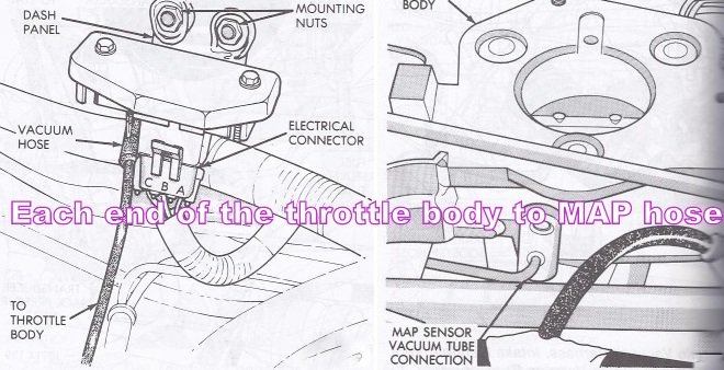
-
testing wiper/blower motor
cruiser54 replied to a bum with money's topic in MJ Tech: Modification and Repairs
Have you seen this? CRUISER'S MOSTLY RENIX TIPS IMPROVING BLOWER MOTOR PERFORMANCE NOVEMBER 28, 2015 CRUISER54 30 COMMENTS On 1984 to 1990 MJs and XJs, the blower motor’s factory grounding point is on the driver side inner fender under the sheet metal screw. This ground is shared with windshield wipers, front windshield washers, rear windshield washers, AC clutch relay, fan control relay, fog lamps, fan motor, headlamps, front turn signals, front side markers, and park lamps. So your blower motor has its ground point 10 feet away from where it is located!! What we’re going to do is leave that ground intact and also ground the blower motor on the passenger side inner fender much closer to the blower motor itself. This will also benefit the other components on the factory ground circuit. Take this opportunity to refresh the factory ground as a matter of course. Remove the screw, scrape the surface to bare metal and reinstall the screw securely. Here’s what I do to get the ground much closer to the blower motor and add another ground point to this overloaded ground circuit. Find the blower motor connector on the passenger side. Red and Black two wire connector. Find a location where the black wire can be made to reach the passenger side inner fender, and cut the wire. You may have to do some rerouting of the harness to achieve this. Take both cut pieces of wire and put them together into a yellow eyelet and crimp. Fasten the eyelet to a place on the passenger side inner fender with a sheet metal screw after applying OxGard to the contact surfaces. Be sure to scrape the attaching point on the fender to bare metal first. Your blower motor will now turn faster and last longer, and the other electrical components on the circuit will benefit from a better ground path. -
Clutch not fully disengaging.
cruiser54 replied to Dickinson County Comanche's topic in MJ Tech: Modification and Repairs
Before replacing anything else, try this. Pump the clutch pedal about 50 times and then walk away for a half hour. come back and see how the pedal feels. That said, and based on my experience, along with it getting harder to disengage the clutch with higher temps, perform the "slip, stink, park" method I outlined above. -
Clutch not fully disengaging.
cruiser54 replied to Dickinson County Comanche's topic in MJ Tech: Modification and Repairs
So, was the clutch replaced at the same time as the hydraulics? If so, it could be a combination of issues. -
Clutch not fully disengaging.
cruiser54 replied to Dickinson County Comanche's topic in MJ Tech: Modification and Repairs
Yep. -
Clutch Pedal Arm, pulled and welded.
cruiser54 replied to KANTANKRUS's topic in MJ Tech: Modification and Repairs
Yes -
Clutch not fully disengaging.
cruiser54 replied to Dickinson County Comanche's topic in MJ Tech: Modification and Repairs
Another thought, the disc heats up and expands. I can't tell you how many times we put new clutches in and experienced this issue. It's an easy fix. Drive down the road in 4th gear at 35 MPH or so. Push the clutch in and rev the motor up. Slip the clutch about 10 times until you just start to smell it. Go park the truck and let everything cool down for a few hours. -
They used Japanese transmissions..... It will never happen. This falls into the category of "if you have to ask....".
-
Rough idle, dies when warm
cruiser54 replied to speeding_infraction's topic in MJ Tech: Modification and Repairs
You need a new one -
Rough idle, dies when warm
cruiser54 replied to speeding_infraction's topic in MJ Tech: Modification and Repairs
REplace the o-ring on it. -
Electric Fan Sensor Problem
cruiser54 replied to Warren99's topic in MJ Tech: Modification and Repairs
nice. -
Rough idle, dies when warm
cruiser54 replied to speeding_infraction's topic in MJ Tech: Modification and Repairs
WHAT is hissing? -
I'll bet you fix the defrost issue and your other issues will magically disappear.
-
Here's where to begin: