


Ωhm
-
Posts
3166 -
Joined
-
Last visited
-
Days Won
6
Content Type
Profiles
Forums
Gallery
Everything posted by Ωhm
-
I thought 91/92 grilles couldn't be installed upside down. Welcome to CC forum.
-
Any idea as to what temperature that small Radiator Fan Switch closes at?
-

Battery drain from Starter Relay?
Ωhm replied to EdJarHead's topic in MJ Tech: Modification and Repairs
-
Treat it like a fusible link, start low (142°C). Keep in mind what @Eagle_SX4 said. DC Motors that turn slow/slower (rpm's) can't create counter voltage, causing increased current flow in the circuit.
-
Pin30(COM), I believe is correct. Pin87(NO) should show as LT GRN and Pin87a(NC) as BLK.
-
I thought REM showed both readings. Manual does say no REQ without SEL. Could be reason for only one display reading. ECU still needs to see both signals. Try this: Remove the AC Clutch Relay. Jumper (fused) 12vdc to D2_6. Both AC Clutch and Cooling Fan should energize. Use CAUTION.

-
Doesn't REM have two AC readings, both Request and Select? ECU needs both for AC Clutch Control.
-
_mj1988electricalmanual_1.pdf
-
This will also shift injector timing and when the ECU looks for KNOCK. At least on the 4.0L. Advancement's must be acceptable since they sell the part.
-
Battery drain from Starter Relay?
Ωhm replied to EdJarHead's topic in MJ Tech: Modification and Repairs
Check voltage at the following pins (fuse block, one side of fuse or the other). Looking for clean 12vdc. -ETR fuse -BATT feed (above the ETR fuse) -HD LAMP/DLY -ABS BATT -
@Eagle Yeah, 88electrical manual show 149C(300F) for thermo cutoff. Voltage drops are used for Headlamp SW dimmer, ballast resistor (4L) and the big one (lots of HEAT), Blower Motor Speed. Hope you get what you're looking for.
-
-
System Sentry Sensor Location Dilemma
Ωhm replied to eaglescout526's topic in MJ Tech: Modification and Repairs
Need for precise and accurate drilling here for the exact location of the sensor. I think engine oil level was 1qt low, light ON. Don't know what rear axle level SPEC is. -
If you or someone else performed Cruisers Tip #29 (Fuel Pump Grounding), then pump will continue to RUN when ON.
-
How is the Closed Throttle Switch (CTS) tested? Can you use D2_13 and D2_7 for testing purposes. ECU might need to know this information for IDLE.
-
Are you running an oil pressure gauge somewhere. Not a sending unit or idiot light, those are electrical.
-
Is that a wire or is it tubing?
-
Battery drain from Starter Relay?
Ωhm replied to EdJarHead's topic in MJ Tech: Modification and Repairs
Don't. Took me years and I still get fooled. Welcome to the madness. -
Battery drain from Starter Relay?
Ωhm replied to EdJarHead's topic in MJ Tech: Modification and Repairs
Flip that connector in your hand. Connector end views are a world of madness.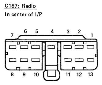
-
Battery drain from Starter Relay?
Ωhm replied to EdJarHead's topic in MJ Tech: Modification and Repairs
Looking at the posted photos, looks like C187_3 is blank. Interesting. Needs checking into. -
Battery drain from Starter Relay?
Ωhm replied to EdJarHead's topic in MJ Tech: Modification and Repairs
Yes. If shorted to GND or shorted to a circuit with current draw (EX: lamps) could cause drain issue. C188_C should act the same, voltage wise, as C187_4. No need to look at it now. Wasn't this the pinout reading for C187? -
Battery drain from Starter Relay?
Ωhm replied to EdJarHead's topic in MJ Tech: Modification and Repairs
Looks now like a voltage drop on C187_4. Should show the same reading on C188_C. If reading looks good, when measured, try wiggle testing the harness. Was this 'direct connect to battery' on C187_4 or on both C187_4&5? -
Taken from his webpage. Photo 59 of 388.
-
Battery drain from Starter Relay?
Ωhm replied to EdJarHead's topic in MJ Tech: Modification and Repairs
This seems like the circuit between RADIO Fuse and C187_5 is a problem, yet original radio still worked. RADIO Fuse is powered by the IGN_SW_A (ACCY&RUN). Can you check C187_5 (KEY ON or ACCY) using a testlight. Using the testlight causes current to flow in the circuit. With HD_LP_SW OFF, C187_11 receives power from the RADIO Fuse thru RELAY(OFF). Once HD_LP_SW is ON, RELAY is picked (ON) then both C187_10&11 become DIMMER circuits. This would be for a factory radio. -
Battery drain from Starter Relay?
Ωhm replied to EdJarHead's topic in MJ Tech: Modification and Repairs
Check pages 56 & 59. _mj1988electricalmanual_1.pdf