

eaglescout526
-
Posts
12138 -
Joined
-
Last visited
-
Days Won
13
Content Type
Profiles
Forums
Gallery
Everything posted by eaglescout526
-
'86 MJ 2.5L ECM....good?
eaglescout526 replied to SoCalManche's topic in MJ Tech: Modification and Repairs
Ok lets recap MAP sensor A-Ground B-Output voltage C 5 Volts. Since the ECU is a computer and all computers love 5V systems, the sensor should get 5V Terminal 16 is MAP supply voltage Terminal 17 is MAP ground. So you tested the ground to the supply voltage, which means you got a reading but not the right reading we are looking for. Try A and T17 Then try C and T16 and see what comes up. -
Bottom door paint/trim
eaglescout526 replied to Manche757's topic in MJ Tech: Modification and Repairs
I'm willing to bet it is factory paint job but the bumper and caps were probably done to match at some point. Looking at the rear in the top pic looks like they didn't paint the rear bumper caps. -
Well, I was about to give you a hard time for cutting up a good bed mat but I see it is already cut up for the tool box so I guess youre off the hook. But that is all rather smart way to put in a roll bar with the bed mat.
-
Open radiator options
eaglescout526 replied to Fernando87mj's topic in MJ Tech: Modification and Repairs
Good luck finding a suitable cap for that bottle. Its ironic how crown makes that bottle but no cap to go with it. I found that the old 5 quart oil bottles worked as a cap. I know there was some NOS caps left but I don't know where now. -
Jeep Comanche Coin
eaglescout526 replied to RAFA2009's topic in Craigslist/Marketplace/eBay... i.e. Not Your Stuff
Geez, I would expect $100 for the gold one not the basic factory workers coin. -
I want to do an idiot light cluster as a decoration piece with power. It would be pretty cool use of a worthless cluster.
-
1986 2.5L TBI 4spd Manuel won't start
eaglescout526 replied to LTZ_3's topic in MJ Tech: Modification and Repairs
Check your grounds and the fuel pump and its associated relay? Now when you say you have spark is your CPS outputting the correct voltage? -
Courtesy light questions
eaglescout526 replied to knever3's topic in MJ Tech: Modification and Repairs
Blue box is for headlight on buzzer and black box does not have it. -
86' 2.5 4 to 5 speed swap?
eaglescout526 replied to TheDude's topic in MJ Tech: Modification and Repairs
No, should be exactly the same length. -
86' 2.5 4 to 5 speed swap?
eaglescout526 replied to TheDude's topic in MJ Tech: Modification and Repairs
The only thing different between the two AX’s is the addition of a fifth gear. It should be a direct plug and play swap. But if his is an 86 it might have the external set up in which case you will have to swap the front bearing retainers as one has a metal sleeve that goes over the input shaft while the internal slaves do not. -
Wow, awesome! I’ve got plenty of time and am in no rush for one.
-
100 $ camper shell colorado
eaglescout526 replied to jdog's topic in Craigslist/Marketplace/eBay... i.e. Not Your Stuff
OMG I am dying! That is hilarious. -
100 $ camper shell colorado
eaglescout526 replied to jdog's topic in Craigslist/Marketplace/eBay... i.e. Not Your Stuff
Off topic slightly but I decided to see what folks were selling in my state and came across an 84 J10 with a GMC steering wheel. Thought that was a bit funny with an obvious column swap. -
'86 MJ 2.5L ECM....good?
eaglescout526 replied to SoCalManche's topic in MJ Tech: Modification and Repairs
Sounds good. Hopefully we can get to the bottom of this issue of yours. Also fun little note. The book strongly recommends the ECU be the last thing to replace as they are reliable. -
'86 MJ 2.5L ECM....good?
eaglescout526 replied to SoCalManche's topic in MJ Tech: Modification and Repairs
Yes I do. My dads fluke leads are really really long so that's my bad for thinking you had some that are of good length. -
'86 MJ 2.5L ECM....good?
eaglescout526 replied to SoCalManche's topic in MJ Tech: Modification and Repairs
I don't think the TBI book is a PDF yet. It is a goal to get my books into a PDF. Ok here is the 86-90 2.5L* connector pin out: To adjust the TPS you leave the probes in the connector and loosen the screws on the sensor till you can move the sensor back and forth but not incredibly loose otherwise it will be hard to adjust the sensor. Once the screws are loose(again not all the way out just enough to move it with some effort), move the sensor back and forth until you achieve somewhere between 4.6V-4.7V. I have mine at 4.64V but yours may differ. *book shows our 2.5L as a 2.46L which is the total Litres of our engines but AMC rounded it up to save breath.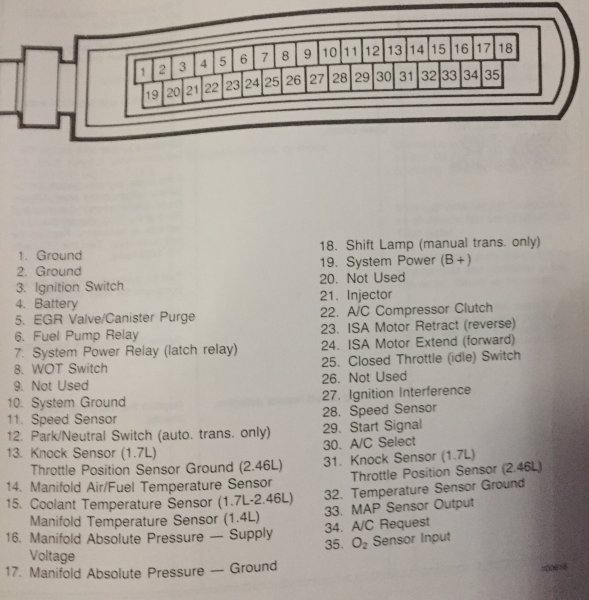
-
'86 MJ 2.5L ECM....good?
eaglescout526 replied to SoCalManche's topic in MJ Tech: Modification and Repairs
Yes, that will show you your output voltage with key one engine off at the sensor. Terminal 33 on the ECU should show the same output voltage. Ground testing the MAP for the ECU is done with probe in A and probe in terminal 17 of the ECU. You can also check the Ohms of the ground at the sensor and the battery to see how bad the resistance is. 5V is on C and use A for the ground. Then check terminal 16 on the ECU for the same 5V. For the TPS is that output or the 5V input? -
'86 MJ 2.5L ECM....good?
eaglescout526 replied to SoCalManche's topic in MJ Tech: Modification and Repairs
Ok MAPs output should be around 4-5V. 4.1V is fine. I would leave the ground probe in the sensor and use the power probe on the ECU connector and see if there is a voltage drop between the sensor and ECU. You can also test the MAPs ground Ohms at terminals 2 and 17. -
'86 MJ 2.5L ECM....good?
eaglescout526 replied to SoCalManche's topic in MJ Tech: Modification and Repairs
Also the TPS input should be 5.0V with the throttle wide open and engine off at B and C. Jeez its been a while since ive done the TPS. I had them backwards. A is the output on the TPS and that should be 4.6V-4.7V. My bad. Good thing I have this book. -
'86 MJ 2.5L ECM....good?
eaglescout526 replied to SoCalManche's topic in MJ Tech: Modification and Repairs
Its not a good thing when the book says the input should be 5.0V (+or- 0.5V) Terminal 16 of the ECU should also show 5V for the MAP circuit. -
'86 MJ 2.5L ECM....good?
eaglescout526 replied to SoCalManche's topic in MJ Tech: Modification and Repairs
Is the ECU back in the truck? 9V for output is really really high. OK had to get the TBI book C is the 5V circuit on the MAP, A is ground and B is output. MY bad. TPS is still the same as before. -
'86 MJ 2.5L ECM....good?
eaglescout526 replied to SoCalManche's topic in MJ Tech: Modification and Repairs
A should be input and C is output. I have trouble back probing mine too from time to time, so its not just you getting that issue. TPS is not based on resistance. Also C is used to make adjustments for the TPS, usually between 4.6V-4.8V is the proper output for the TPS but I like to have it in the middle at 4.7V. -
'86 MJ 2.5L ECM....good?
eaglescout526 replied to SoCalManche's topic in MJ Tech: Modification and Repairs
MAP sensor should be on the firewall. TPS is on the base of the throttle body. Every sensor should get ~5.0V with key on engine not running. -
I don't know why but I find this image pleasing to look at. Really clean and well done.
-
Not sure. Original idea was for Little Red.