

eaglescout526
-
Posts
12138 -
Joined
-
Last visited
-
Days Won
13
Content Type
Profiles
Forums
Gallery
Everything posted by eaglescout526
-
'86 MJ 2.5L ECM....good?
eaglescout526 replied to SoCalManche's topic in MJ Tech: Modification and Repairs
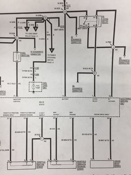
Right right right. My brain is going a mile a minute. But we can confirm that jumping the relay causes the pump to run, so we can test the voltage and see if we are seeing 12V or not. Back up the line to 30 on the relay, it goes to a red fusible link. Then 86 on the relay goes to splice "B" which is a yellow wire all the way to splice "E" then splice "D" to the ignition switch. I wonder what T3 shows at the ECU connector? Splice "B" also shows to go to D1_2. Looks like the MAP and TPS share the same 5V circuit from the ECU. Ill admit, I'm learning right here with you. -
This makes sense why you don't see little dealer ships like that anymore. Damn Iacocca. So theres probably dozens of AMC dealers that are hidden in small towns because of the big dealer ship idea.
-
Youre gonna hit a point where I will be jealous of your MJ and some of the neat factory options like a hidden winch.
-
'86 MJ 2.5L ECM....good?
eaglescout526 replied to SoCalManche's topic in MJ Tech: Modification and Repairs
Both would indicate open loop but I would test for both just to see what we could be looking at. And let me know on that tool kit and ill see if I can hunt down a semi cheap kit to add a pressure gauge to mine. Also the injector is not supposed to have more than 10 Ohms of resistance. -
'86 MJ 2.5L ECM....good?
eaglescout526 replied to SoCalManche's topic in MJ Tech: Modification and Repairs
This one definitely is a unicorn of issues. I'm not sure if they have a kit for all fittings but hopefully they have the right one for our TB's. If they do let me know, id permanently hook one up. Ok looking at the 86 electrical book, from 87 on the FP relay, that wire goes to splice "K" which goes up to C113 that goes to splice "N" then one of the five other orange wires goes to the fuel pump with C100 then to C200 then to the Sending Unit. So theres only two connectors between the splice and tank. Two other orange wires go to the laod swap relay which is probably that silver one in the pic and another one goes to the PS switch. Another orange wire goes to C219 which is not used. Thank goodness for dual monitors. -
'86 MJ 2.5L ECM....good?
eaglescout526 replied to SoCalManche's topic in MJ Tech: Modification and Repairs
Relay, solenoid, they do the same thing. Man 86 is an animal that's for sure. On the side of the TB is an allen head bolt snugged away by the fuel lines facing the drivers side fender. If you can manage to find a pressure gauge to fit that port you can see what the fuel pressure looks like. Have you seen any fuel leaks around the TB area? -
'86 MJ 2.5L ECM....good?
eaglescout526 replied to SoCalManche's topic in MJ Tech: Modification and Repairs
I wonder where your starter relay is. I looked at my 86-87 parts book and saw a couple like that silver one but I know its not the anti diesel timer so it could be the power steering relay. -
'86 MJ 2.5L ECM....good?
eaglescout526 replied to SoCalManche's topic in MJ Tech: Modification and Repairs
Do you have AC or Fog lights? Possibly O2 relay. I meant the other 5 pin connectors, the GM weatherpak ones. Gonna need TNT to blow this stump. -
MJ Towing with Dolly ?
eaglescout526 replied to AMC86Kid's topic in MJ Tech: Modification and Repairs
Actually it could rack up miles on the speedo. If the output shaft is spinning, chances are so is the speedometer and the odometer. So even leaving it in neutral is fine but youll rack up miles. I'm sure theres a liability reason and stuff like that that I can not think of. -
'86 MJ 2.5L ECM....good?
eaglescout526 replied to SoCalManche's topic in MJ Tech: Modification and Repairs
Sure!! If we weren't in this current situation the world is in, lol. First thing I would look at before absolutely diving into the harness is cleanliness. How clean are the FP relay and the starter relay contacts. Possibly a connector could be loose on that relay. Had that happen once, wouldn't even engage the starter until I found a connector coming unplugged yet it had started the day before that incident. Are there two 5 pin connectors by the passenger side shock tower by the relay center? -
'86 MJ 2.5L ECM....good?
eaglescout526 replied to SoCalManche's topic in MJ Tech: Modification and Repairs
Sounds like fun doesn't it? Otherwise the book doesn't really say what else to do other than repair the harness. -
'86 MJ 2.5L ECM....good?
eaglescout526 replied to SoCalManche's topic in MJ Tech: Modification and Repairs
So the book says it should be zero volts after engaging the starter motor. Then says repair the harness as necessary. Then it says to check the MAP sensor and repair as necessary. And of course the last test I wish I had is the MS 1700 ECU scanner. -
'86 MJ 2.5L ECM....good?
eaglescout526 replied to SoCalManche's topic in MJ Tech: Modification and Repairs
I mean you could hunt down a special test bulb but something like a courtesy light would also work for the test bulb. The only other ground would be the one from the engine to the fire wall which you have cleaned and replaced in your pic. The injector pulses, that's all I know. My guess is it pulses and the fuel enters and the injector pulses it down into the throttle body in mist like fashion so the fuel atomizes when it gets to the combustion chamber. But yes there needs to be a good 14-15PSI of pressure for the fuel system. Everything except the CPS is VDC. -
MJ Towing with Dolly ?
eaglescout526 replied to AMC86Kid's topic in MJ Tech: Modification and Repairs
When I got my MJ my dad and I towed it with a car dolly with the front wheels on. Course we took back roads to get home. -
'86 MJ 2.5L ECM....good?
eaglescout526 replied to SoCalManche's topic in MJ Tech: Modification and Repairs
Ok so here's a couple troubles from the TBI book Engine starts but won't idle: Fuel pump inoperative or ignition system malfunction. Check fuel pump. Check the ign system. Repair as necessary. Check the start signal after engaging the starter motor. Voltmeter from D1 pin4 to D1 Pin3 should indicate zero volts. Repair harness as necessary. Check MAP sensor. Repair as necessary. Engine will not start: Defective Wide Open Throttle swtich(you might have this if theres no pressure switch on any of your power steering lines.) Low Bat voltage Fuel supply low Low fuel pressure Fuel pump inoperative Defective secondary ignition circuit Primary ignition input to the ECU defective No bat voltage applied to the injector(12V from one pin top chasis ground) Injector Ohm resistance too high(less than 10 Ohms) ECU is not switching the injector Leaking injector No start signal voltage ISA motor plunger not extended Coolant temp sensor inoperative. These are the possible causes the book lists. -
'86 MJ 2.5L ECM....good?
eaglescout526 replied to SoCalManche's topic in MJ Tech: Modification and Repairs
Good as in the pump turns on and runs. But you say you don't hear it for that one second with and without relay correct? -
'86 MJ 2.5L ECM....good?
eaglescout526 replied to SoCalManche's topic in MJ Tech: Modification and Repairs
Me, I wouldn't rush out and get one just yet. We know the ECU will receive the voltage signal and tell the coil to spark which we can confirm by pouring fuel down the TB. So the CPS is not the entirety of the issue. We need to figure out why the pump won't turn on for one second and during crank/run. Has the pump been confirmed good before? -
1988 jeep in Denver 2800
eaglescout526 replied to jdog's topic in Craigslist/Marketplace/eBay... i.e. Not Your Stuff
If you do that youll start to see your dream MJ. -
'86 MJ 2.5L ECM....good?
eaglescout526 replied to SoCalManche's topic in MJ Tech: Modification and Repairs
What kind of MJ rabbit hole have we plunged into? Hopefully this won't be like the one where the hood lamp wire was plugged into the coil, but this is confusing to say the least. Yes check the CPS side. I think .3 is a good number. I know Ohm said 2.5VAC . Ok here is tip No.7 from cruisers website: "Unplug the harness connector from the CPS. Using your voltmeter set on AC volts and probing both wires in the connector going to the CPS itself as shown in Figure 2 as Connector A, crank the engine over. It won’t start with the CPS disconnected. You should get a reading of .5 AC volts." "If you are down in the .35 AC volts range or lower on your meter reading, you can have intermittent crank/no-start conditions from your Renix Jeep. Some NEW CPSs (from the big box parts stores) have registered only .2 AC volts while reading the proper resistance!! That’s a definite no-start condition. Best to buy your CPS from NAPA or the dealer." .32VAC is getting on the low end for the CPS output. -
'86 MJ 2.5L ECM....good?
eaglescout526 replied to SoCalManche's topic in MJ Tech: Modification and Repairs
Well that's odd seeing how with the relay in you get spark and engine fires when pouring fuel down the throttle body. The volt meter is on the Volts AC setting right? This is the only component that requires the VAC setting. -
'86 MJ 2.5L ECM....good?
eaglescout526 replied to SoCalManche's topic in MJ Tech: Modification and Repairs
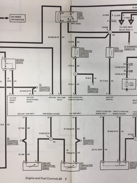
No, he means you can unplug the sensor from the harness and test for Volts AC while cranking. I think he wants to make sure the CPS is sending out the proper signal. here's the 86 engine and fuel management diagram.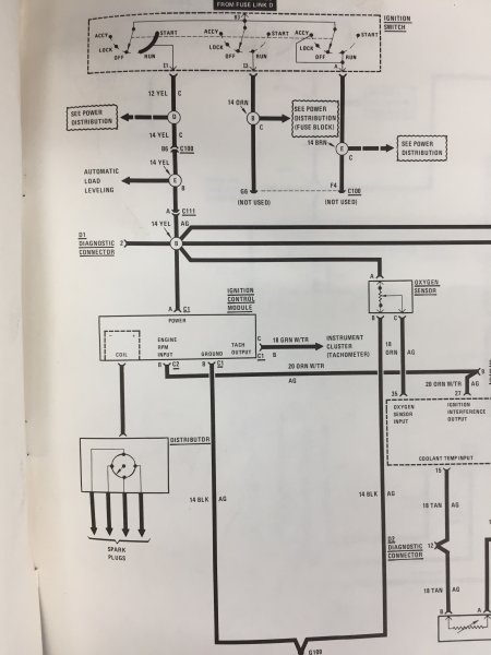
-
'86 MJ 2.5L ECM....good?
eaglescout526 replied to SoCalManche's topic in MJ Tech: Modification and Repairs
Lol no worries. We will find it. We will just keep running down the diag list until we get somewhere. -
'86 MJ 2.5L ECM....good?
eaglescout526 replied to SoCalManche's topic in MJ Tech: Modification and Repairs
Lol good we have continuity there which means no breaks in the harness between the ECU to the relay. Now my 86 electrical manual shows the same as the 88 above but a little bit different but still the same for T6 to the relay. 86 shows to go to the B splice and is triggered by the ignition switch. 30 on the relay is power from fusible link F. 87 goes to splice K which seems to power a few different things. I will have to get a good pic of it in the morn. -
'86 MJ 2.5L ECM....good?
eaglescout526 replied to SoCalManche's topic in MJ Tech: Modification and Repairs
It should be pin 85. TBI book says to check for continuity not necessarily voltage but it didn't hurt to see if the ECU is sending any down the line. I think I have an 86 electrical manual. -
'86 MJ 2.5L ECM....good?
eaglescout526 replied to SoCalManche's topic in MJ Tech: Modification and Repairs
Does your voltmeter have a continuity test setting? Should be a symbol represented as what looks like sound waves by the dial. That would confirm weather theres a break in the wire(no beep) or not(beep) by the multimeter. But testing for volts is a good thing to check too.