


Ωhm
-
Posts
3166 -
Joined
-
Last visited
-
Days Won
6
Content Type
Profiles
Forums
Gallery
Everything posted by Ωhm
-

ECM reading move erratically while watching on scanner
Ωhm replied to JMO413's topic in MJ Tech: Modification and Repairs
Scanner only uses serial data from the microprocessor. If vehicle runs and operates OK, I don't know what to say. Not much help here. -
Link off the internet The Peugeot BA10/5 transmission is a five-speed, overdriven, light-duty, passenger car transmission used by AMC Jeep from 1987 until mid-1989 in the YJ Wrangler, XJ Cherokee and MJ Commanche with the AMC 258 & 4.0L I6. The 10/5 transmission had a poor record for durability and service, and consequently had the distinction of being the transmission with the shortest production run in Jeep history. It was gradually replaced by the AX15 during the 1988 model year.
-
ECM reading move erratically while watching on scanner
Ωhm replied to JMO413's topic in MJ Tech: Modification and Repairs
You mentioned before you had two PCM's (88&89). Did the scanner work OK before on both of them? -
Since old switch bench tested bad (fails to make contact) and new switch bench tested good (makes contact), its more than likely your problem lies in the switch not having enough travel to make contact. Take that piece of Brand New Junk (BNJ) and tell them you want a newer one before looking into any tranny work.
-
If you still have the old switch, check its operation with a ohmmeter across the terminals, by pushing in on the ball. Could determine if switch (old or new) is at fault or is it something internal to the transmission.
-
Good work. Good find. Hope this ends your electrical nightmare.
-
Ask if you can move this Post to "MJ Tech: Modification and Repairs". This will put more eyes on the subject.
-
Control your add-on relay (coil side) by using the ORN wire from the fuel pump relay (FPR_87). Do not cut this wire, but instead "T" into it. This will allow your add-on relay to act, function as the factory FPR. That is, the external fuel pump will prime during KEY_ON for 2-3 seconds and remain ON during CRANK, then RUN. Yes, ORN/BLK must be a complete circuit, as mentioned above.
-
Where did you locate the add-on relay for the external fuel pump? Does this vehicle have a fuel pump ballast resistor? Ceramic block on the left front inner fender. Two single wires (ORN).
-
ACC circuit drops out (no voltage) during CRANK.
-
Don't forget the hole needed for the wiring.
-
Yeah, lets hope someone else will chime in, but as of now, that the way I see it.
-
Not if you pulled out all the relays, it doesn't.
-
Since we can't kill the fuel pump from under the hood and C157 kills the fuel pump, that leaves C100 (ENG to IP) (Bulkhead connector) left to check (separate). In other words, your short to voltage is between C157 and the battery. Put a voltmeter on the fuel pump wire (should read battery voltage) and trace the wire(s) back looking for wires touching each other. Best I can do sitting in my chair.
-
With C157 connected, is pump on or is pump off?
-
Disconnect C352 (single bullet connector) (ORN/BLK) located near the RH shock tower. Connect C157.
-
Disconnect C157 (IP to CAB). Flat 6 pin connector located above/around the Parking Brake. This will divide the circuit in two.
-
Disconnect the BAL connector (ORN/BLK) at the starter relay. Disconnect one of the two wires (both ORN/BLK) at the fuel pump ballast resistor. Does either one of these turn off the fuel pump?
-
tries to die when clutch pressed to decelerate
Ωhm replied to aprildaisy's topic in MJ Tech: Modification and Repairs
What were the spark plugs gap set to? Not sure exactly what the specs calls for. Anyone? -
Remember, we don't bounce like our grandchildren do, anymore.
-
More starter problems...
Ωhm replied to Wounded_Fighter's topic in MJ Tech: Modification and Repairs
All dash lines connect to the starter relay (batt) terminal. -
More starter problems...
Ωhm replied to Wounded_Fighter's topic in MJ Tech: Modification and Repairs
Follow the electrical manual. -
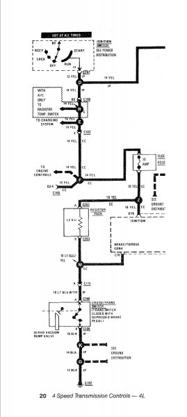
Reason for my concern on Cruise/Trans switch logic. TCU_C10 seems to be a voltage sensitive digital switch. This digital switch tells the TCU processor when the brakes are being applied and too disengage the torque converter (S3) from lockup, if conditions are such that the torque converter is in lockup mode. TCU processor controls S3 no differently than the way it controls S1 & S2. That is too say, TCU processor controls a high side driver (12vdc) to component (in this case S3) to ground. Same applies to S1 & S2. Even the fuel injectors are controlled the same way, high side driver (12vdc) to component to ground, but that's a different module (processor). Circuit function (the wiring). When Cruise/Trans switch is in the open position, voltage is being applied to TCU_C10, since no current (amps) is flowing in the circuit. Once Cruise/Trans switch is closed and ties the circuit to ground, current flows and all available voltage is dropped across the resistor pack (1.2kohms). The two (2) conditions are TCU_C10 sees 12vdc (brakes are not being applied) or 0vdc (brakes are being applied). So this is how I see the circuit wiring and how I see the circuit function (purpose). Please advise on any other explanation.
-
I (we) are only as good as the documentation and yes, documentation has been known to be incorrect. I still don't understand how flipping the switch logic will make things okay.
-
I still think you need a switch, when installed in the vehicle, where both switches (Brake & Cruise/Trans) are closed when the brake pedal is depressed.