NickyV
-
Posts
159 -
Joined
-
Last visited
Content Type
Profiles
Forums
Gallery
Everything posted by NickyV
-
Wow... Add this EQ to the wish list. Wonder if I'll ever be able to find one in working condition. It's so cool that it has a pair of memory slots. This would be ideal for going between music and news/audio books. I recently installed some Jensen tweeters I found in the JY. They work and they are not overpowering as some in other threads have warned about... at least they aren't overpowering to my ear when listening to music. However, when I switch over to news radio or play a book on tape through my recently-added Bluetooth module, it can start to get a bit grating depending on the timbre and vocal qualities of the narrator. I was listening to one the other day where the "S" sounds were starting to give me a headache. On the iPhone, the EQ settings are kind of buried. I wonder if I could set up something using Shortcuts for when I'm using it to listen to podcasts and books on tape... Hmmm...
-
Build Your Own Harness: A Step-By-Step Guide
NickyV replied to NickyV's topic in MJ Tech: DIY Projects and Write-Ups
Huh... Thanks for letting me know about these, @89 MJ. I literally didn't know they existed. I mean... some of the butt connectors I have are probably actually just this. Wish I'd realized that. Will keep in mind for the future! -
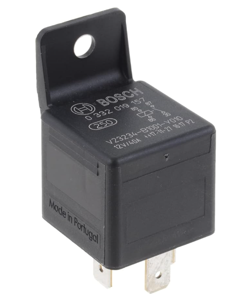
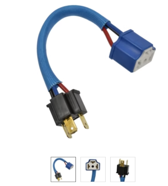
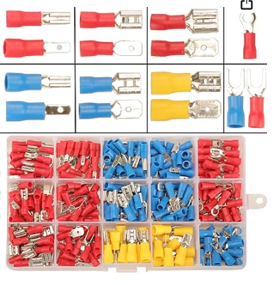
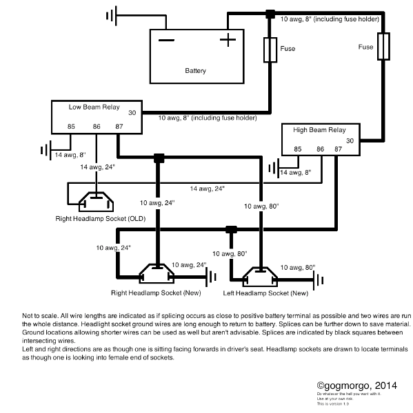
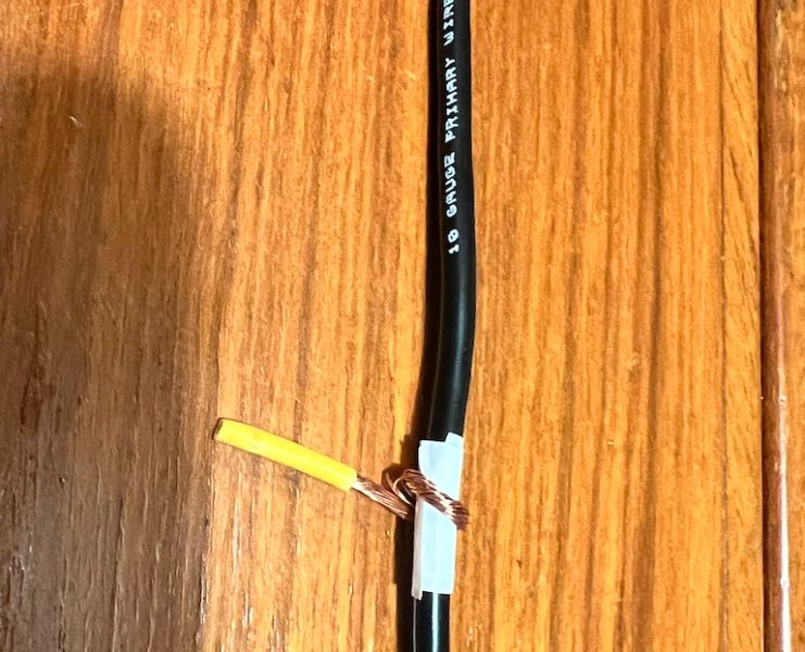
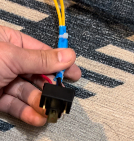
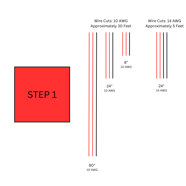
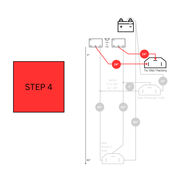
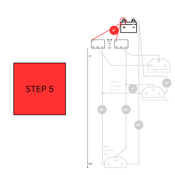
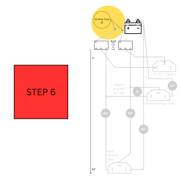
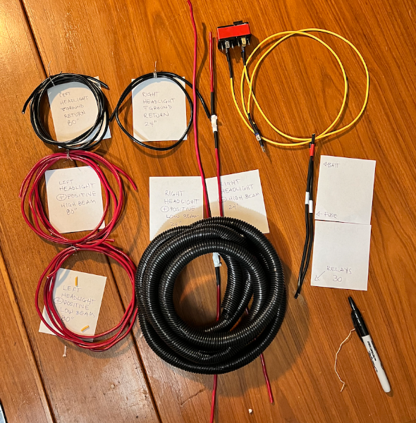
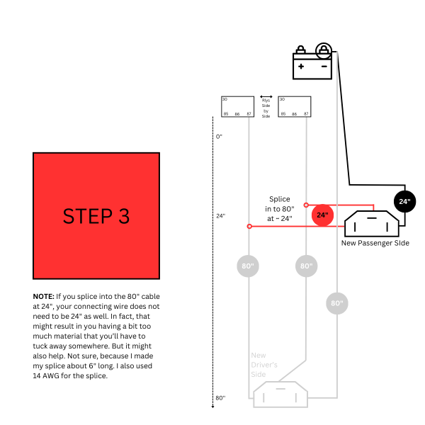
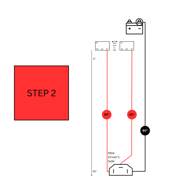
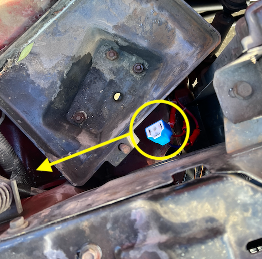
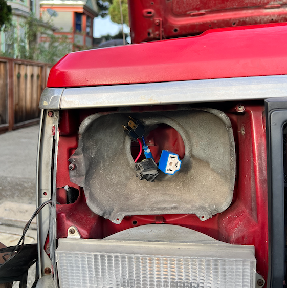
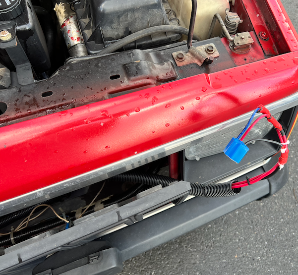
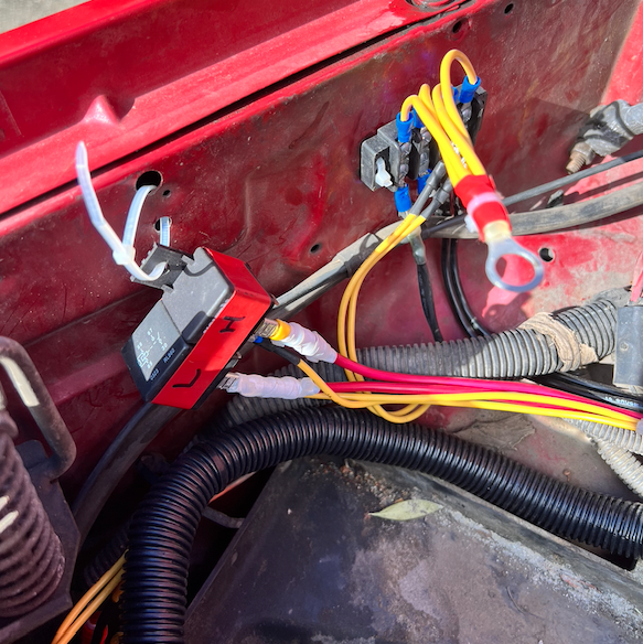
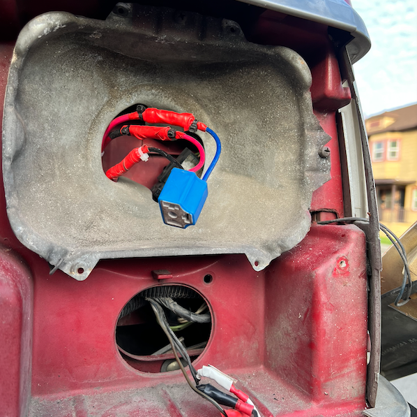
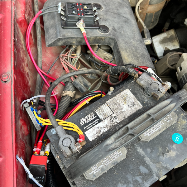
Greetings, Fellow Comanche Enthusiasts! I’ve spent the past few months diving into projects on my 1987 2.5L, 2WD, Short Bed, and this forum has been an invaluable resource. I’ve really enjoyed the time I get to spend just working with my hands and not thinking about emails I have to send. But it occurs to me that I’ve spent a lot of time asking you all questions. I want to give back with a tutorial of my own. I’m much newer to this than many of you, so I welcome any notes on things I could have done better or things I’ve done flat-out wrong. I’m going to write a step-by-step guide on how I built a Headlight Harness Upgrade using @gogmorgo’s diagram. And I’m going to add some diagrams of my own. I hope this ends up helping someone else down the line. NOTE: This is a LONG write up. If you know what you're doing, I suggest taking a look at the diagram below and then the step by step slide show I have at the end. Step 1: Assemble the Materials The first thing I did was add up the total length of 10 AWG and 14 AWG wire that the diagram calls for. The following list turned out to be a little more than I needed, so I think it’s the perfect amount. WIRE: 10 AWG: 30 Feet or 360 Inches 14 AWG: 16 + 48 = 5 Feet or 60 Inches RELAYS: Two 30-amp headlight relays with the following connections: 30, 85, 86, and 87. Here's an example. This one is 40 amps, but you get my drift. H4 HEADLAMP SOCKETS: I scratched my head on this one for a while, because I was unfamiliar with it. Also, all the auto parts websites have my vehicle information by now and they were telling me certain headlights didn’t fit my MJ. I turned off the vehicle-specific search function when I was searching and that helped open up the results. I ultimately went with this one, because it was available locally and the connector was ceramic, which I’ve heard is better than plastic. Makes sense when high temperatures are in play, right? I also wanted to use the male end of one of them to make the connector for the existing OEM harness (see the second picture). OTHER MATERIALS: I had most everything else I needed already, but you’re going to need things like wire strippers/crimpers, big box of wire terminal attachments, a ton of zip ties, and electrical tape. Some other nice-to-haves are a soldering iron, heat shrink wrap, a heat gun, and other electrical components like that. Step 2: Plan Your Build I’ve charged headlong into way too many projects. And honestly, I could have taken more time with this one. But with a project like this, it really helps me to lay everything out in front of me. I looked at @gogmorgo's plans over and over again and cut most of my wire to length before I did anything else. I also labeled my lengths of wire and cross referenced them with the drawings to see if it all made sense. One thing I wish I had done was also plan what kinds of terminal heads I was going to use at each juncture. Doing this would have saved me some time down the line. Step 3: Slow and Steady (Learn From My Mistakes) If you’re brand new, or relatively new (like me), don’t get flustered. Take your time. Like Gogmorgo says, the diagram is not to scale, and it can be hard to visualize at first. Here are some things that took a little while to click for me: Your relays are going to be right next to one another and very close to the battery. Once the new harness is built it will form the shape of a capital “L” — running from the battery on the passenger side of the engine bay, down to the passenger side headlight, then to the driver's side headlight. The short length of the “L” runs from the battery to the passenger side headlight. The long length of the “L” runs from the passenger headlight to the driver’s side headlight. All of the 24-inch lengths of wire correspond to connections at the passenger side headlight. All of the 80-inch lengths of wire correspond to connections as the driver’s side headlight. If you do it like I did, you will have to do at least two splices. These will go on the positive lines. There were two ways I considered doing this. One way would be to connect the positive lines directly to the shovel terminal that attaches to the 87 terminal prongs on each of the two relays (high and low beam). Doing it this way will require the full 24-inches of wire. You may also need to get creative with how you connect the two ends of 10AWG wire to the shovel. Another way is to splice the shorter length of wire roughly at the right angle of the “L” shape that this harness will form when it is installed. Doing it this way will allow you to save a little bit of wire. This second way is the way that I did it. You do not need to splice any of the ground wiring. You do not need to splice the battery-to-relay wiring. Instead, you can just make two 8-inch lengths of wire. On one end attach them to the battery. In the middle, place your in-line fuses. On the other end place a shovel terminal connector to attach to the 30 prong on each relay. If you end up using a left over male H4 connector, remember to connect your wires as a mirror image of the diagram above. I made a mistake here and didn't discover it until the harness was installed. I had to strip wires and make some new connections while crouching at headlight level. Not fun. If you notice, in the picture above, there is a short length of red wire that isn't connected to anything. But that SHOULD have been connected to the high beam relay. Which leads me to No. 7: If you notice in the diagram above, both high beam connections are on the left hand side of the female connector and all the low beam connections are on the top of the female connector. Remember that! Step 4: Splicing & Dicing I was practically brand new to splicing when I started this project. I am also very bad at soldering, and I don’t have a great soldering iron. Here’s how I ultimately spliced the positive cables together: Cut out a very small segment of the 80-inch positive wire. You can use the wire cutters to make the first two cuts around the outer edge of the wire. Then you’ll need a razor blade to cut from one of those cuts to the other cut. Then you’ll peel the slim piece of wire covering off, as if it were a bandage wrapped around your finger. The location of this splice is very close to the connection point for the passenger side headlight connection. The connectors I used came with 14 AWG wires attached to them. I thought about devising a way to maintain 10 AWG all the way to the headlight connection, but I abandoned that idea, and it was helpful to do so. That’s because it was way easier to wrap 14AWG around the exposed splice point of the 10 AWG wire than it would be to wrap the very thick 10 AWG wire around another 10 AWG wire. I took this picture to help you visualize the process. Picture the white electrical tape as the exposed bit on the 10 AWG wire. The yellow bit is 14 AWG wrapped around the exposed portion. Use a soldering iron or thin strips of electrical tape to help secure it in place. As I said, you’ll need to do this on both lengths of 80-inch wire. Step 5: Making Connections Now it’s time to put it all together. For this bit, I made some diagrams of my own. Red is for positive connections. Black is for negative/ground. Connect all the shovel terminals to the wires going to the relays. Connect the new headlight sockets to the wires. Prepare your connection for the existing OEM plug (female plug on the passenger side). I found it helpful to use zip ties to fasten the longer lengths of cable together as I went along. This helped prevent tangles. When I was done, I covered the whole thing in conduit, which I think was helpful when installing in the MJ. MAKE YOUR CUTS MAKE THE DRIVER'S SIDE CONNECTIONS MAKE THE PASSENGER SIDE CONNECTIONS MAKE THE CONNECTIONS FOR THE FACTORY PLUG MAKE YOUR BATTERY CONNECTIONS MAKE AN INLINE FUSE ON THE BATTERY CONNECTIONS Step 6: Hook it Up! I could probably write a whole tutorial on how to do this as well. It took me a long time and I hit some road blocks along the way. Thankfully there is a detailed installation video from K Suspension that you can watch here. The main difference with the harness in this video is that the grounds do not run all the way back to the battery. I opted to create a harness where the grounds return all the way to the battery, because I hoped that would lead to a healthier circuit. By the way, if you don't want to take the time to build your own, or don't feel comfortable doing it, K Suspension and many other companies make this exact harness. Some of them are even cheaper than what it would cost you in money and your valuable time to do it DIY style. But, at least for me, tinkering is part of the fun! Step 6.1: Hook it Up! (Pt. II) OK... Just thought I'd add a few more pics of the actual install. I didn't document this process perfectly. But here goes: It helps to take the batter out completely. This is also good because you know you won't accidentally create a short while the harness is flopping around. This picture is of when I was thinking I'd snake the harness underneath the driver's side of the battery tray, but you'll actually want to snake it under the passenger/fender side. It's a tighter squeeze, but a more optimal flow. Bring the passenger side connections into the passenger headlight bucket. In this image you see the new male connector, the new female connector, and the old factory female connector (clockwise from top). Bring the driver's side connection over to the driver's side bucket, snaking it along behind the grille. I don't have AC (yet). There was a lot of space back there for me. Bring the new driver's side connection into the driver's side headlight bucket. FYI, getting these connections into the buckets was one of the hardest parts of this — at least physically. It's a real contortion act. Be patient. Wear gloves or be prepared to slice up your hands. I also ended up taking out the turn signal on this side. Not sure I needed to, but I got stuck for a while on this step and I wanted a better view. Figure out where you will place your relays. In this picture, you can see where I chose to put my relay and where I decided to put my negative/ground terminal connection. You can use sheet metal screws, but I used zip ties. I might change that in the future. There were many holes already drilled on the interior side of the passenger fender on my '87, which made this pretty easy. Put it all back together. Don't judge me! I need to clean up my battery and replace cables and all that. It's on my list. Anyway, here is the only picture I have in this entire thread of my inline fuses. The fuse block at the top of the pic has a transparent plastic cover, which is good. I will eventually find a better, cleaner way to mount all this stuff, but this is working for now. All right! I think that is it on this now. Se you all in the comments!
-
Headlight Wiring Harness Questions
NickyV replied to SBpunk's topic in MJ Tech: Modification and Repairs
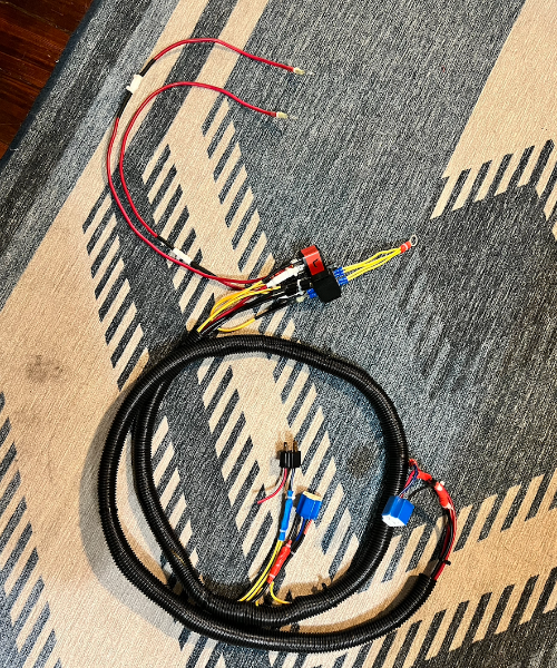
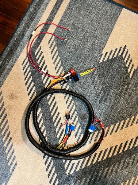
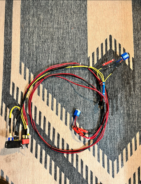
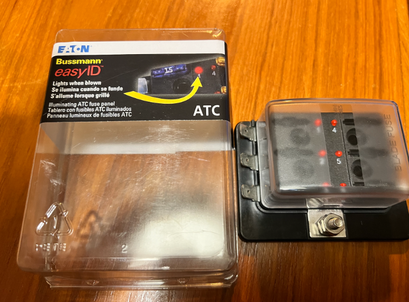
Thanks @schardein. I'm attaching a pic of the fuse terminal I picked up the other day, which I was thinking about returning. It has six terminals. I was thinking that I could use it for a handful of the additional accessories I'm running off my battery, but then I saw 20 amp max and it seemed like people here were recommending 30 amp relays, so I thought this didn't have the capabilities I needed. Maybe I'm wrong about that. (Edit: I would not be surprised in the least if I'm wrong about that.) In addition to the fuse terminal, I'm also going to attach the pics of the harness I've put together. I'm glad to see that some people are saying they paid close to $100 for a high quality one, because that's about what I spent on all the components, and I don't even want to talk about the labor I put into this. Lol. The pictures of the harness have everything except the fuses, which need to go somewhere along the two shorter red cables with the ring tips. I know I can also do inline fuses. I need to go back through this thread and read what some have said about what the fuse should be, but if someone cares to tell me here, that'd be great too!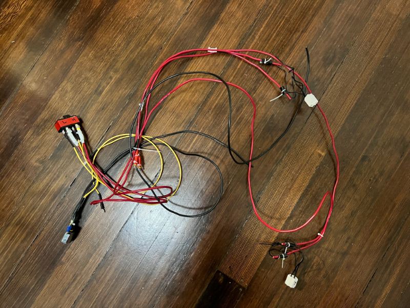
-
Death wobble is trying to come back
NickyV replied to Knucklehead97's topic in MJ Tech: Modification and Repairs
Thanks, @MississippiComanche At this point, I do not have plans to lift the truck. The most "off-roading" I ever do is driving on forest service roads to get to campgrounds, and I've always had sufficient clearance for that. I'm realizing whenever I see conversations about track bars, it usually has to do with a lift. I'm assuming I have a track bar as well, even though it isn't lifted. (Novice question, I know.) What's a good track bar for a non-lifted, 2WD MJ? One day, I want to get 4x4, but it will be a while. -
Death wobble is trying to come back
NickyV replied to Knucklehead97's topic in MJ Tech: Modification and Repairs
Track bar and spicier ball joints! Love it! @MississippiComanche, what tires did you get? Your signature doesn’t mention a lift. Is your MJ lifted? -
Headlight Wiring Harness Questions
NickyV replied to SBpunk's topic in MJ Tech: Modification and Repairs
I am late to this thread and others about headlight harness upgrades. I made a lot of progress last night building my own upgrade. I stopped because it was late and because I want to do this right. I’m following @gogmorgo’s diagram, and I’m trying to do it with minimal splicing and grounds going all the way back to the negative terminal on the battery (or more specifically to a terminal block connected directly to the negative terminal). Some questions I have: 1) What do people recommend for the new headlight plugs? Direct links or part numbers + brands are helpful. 2) What do people recommend for the relays? Same request with links/part numbers/brands. 3) I already have two crimp-on terminal connectors bolted to the positive terminal of my battery and I think it is time to upgrade to a more elegant solution. I’m hoping for a terminal bank with ports. I picked one up at AutoZone last night but didn’t read the package closely. Each terminal is a max of 20 amps. That seems like it won’t do. Anyone have a positive side terminal bank that they like? Thanks! -
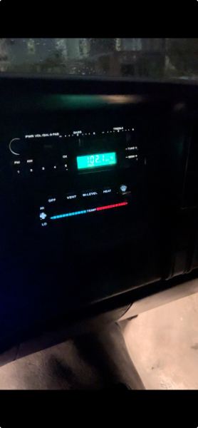
UPDATE: Success! I got the damn thing in. After moving the clock plate out of the way it was still giving me trouble, but I think I figured out the issue. The part of the bracket that attaches to the radio (male?) did not want to fully lock into place on the receiving bracket under the dash. I was wiggling and trying all kinds of things. Then, I accidentally applied some downward pressure on the top of the bracket while I was pushing and it went in. I ended up having to take the radio out once more and when I put it in again, I did the same thing. I think by applying a little pressure I shifted the hook on the bracket just enough to go into place. Maybe it's designed that way? Not sure. But now I have yet another question. The display looks great when the running lights or headlights are on. But when they are off, I can't make out the dial (even in the daytime). I wonder if this is just because the unit is old or if maybe there is a setting I can access by pressing down buttons and twiddling knobs.
-
Death wobble is trying to come back
NickyV replied to Knucklehead97's topic in MJ Tech: Modification and Repairs
Hey! I like that idea, @schardein! Not that I'm trying to be a cheapskate with my personal safety. Heh... -
Death wobble is trying to come back
NickyV replied to Knucklehead97's topic in MJ Tech: Modification and Repairs
Thanks for the intel, @89 MJ. I'll try to get @boxyjeep's attention, or he can drop his recs here, if he sees this post. To answer your question, we only did the shocks. The springs are still the same ones that came from the PO. The mechanic wasn't thinking that the shocks were a big factor in the DW (if they even were), but did think they should be replaced. And thanks for the encouragement too. Confidence is definitely one reason I didn't want to try to mess with the suspension, pitman arm, etc... I do feel pretty handy, though and I bet I can do some of this stuff myself. The other rub, though, is I don't have a driveway and I live on a relatively busy street. Then there's the time factor... anyway, my confidence is growing with every project and many of the ones I have listed in my signature, I plan to tackle myself. I have a question for you related to this: I brought up caster with the mechanic, and he seemed to understand it way better than I do. I think we were both thinking that because I don't have a lift, that it probably isn't the first thing to troubleshoot. However, as much as I trust him, I trust the group wisdom of this forum more. What do you all think? If I don't have a lift, could my issue be with caster? -
Death wobble is trying to come back
NickyV replied to Knucklehead97's topic in MJ Tech: Modification and Repairs
Hello! I am bringing this thread back! I'm also duplicating this post on r/MJComanche. Hope that's OK. I just want to make sure others who experience this can find more information if they're searching for this topic. I'd be interested in hearing back from @Knucklehead97 to hear if you ever fully vanquished your DW. So, as my signature says, I have a 1987, 2.5L, 4-speed (AX4), 2WD. It is not lifted, but it has slightly larger-than-stock tires on it (235/75R/15 as opposed to 225/75R/15). It was a base model, I'm pretty sure. Might have even been radio delete. I've done a lot of work on the cab and creature comforts (stereo, etc), but starting to get into mechanical stuff. I just spent a big chunk of change to try to address the accursed Death Wobble. It seemed to be mostly gone, although when I drove it home from the shop there was a little shimmy that the techs were attributing to tire balance or some related issue. I still need to pull the trigger on balancing the tires or just get brand new ones. I have some 235/75r/15 Goodyear Wranglers on there. They have good tread, but uneven wear and they are pretty old. According to the shop, they are probably 12+ years old. I really trust the mechanic, who I feel did a great job, despite not being a Jeep-specific shop. He runs an outfit that specializes in classic cars. MJs are classic in my book, but they aren't exactly a '56 Bel Air. He knew about Death Wobble and recommended a bunch of things to do. He replaced the pitman arm, put in new suspension which needed to happen, replaced steering damper, installed power steering (yay!) and replaced the clutch master cylinder (unrelated to Death Wobble, obviously, but also needed to happen). Since doing all these repairs, it has never gone back into full Death Wobble, but I can feel it creeping in at the edges. When I reach 55 MPH all the way to about 65 MPH, I can feel shimmy. If I hit a bump going in those speeds, I can feel the shimmy start to become more of a wobble. When I'm on freshly-paved freeway, and feeling brave, I will push it to 70-75 MPH, and it does feel like it starts to smooth out and shimmy less, which I hear may be an indicator that this is a tire balance issue. I have a few main questions: 1) I live in Oakland, Ca. The mechanic I like is in San Jose. It would be great to find a mechanic closer to home and also one who is very familiar with MJs or XJs. Does anyone have any recommendations for a mechanic or just a tire shop that is very good and thorough and would understand my issue? I see that @Eagle and @HOrnbrod swear by the Hunter Road Force tire balancer. That's good to know. 2) Has anyone ever experienced this exact issue, or close? What I mean is doing a bunch of work to fix Death Wobble and then having it start to creep back? If so, what did you do? Did you ultimately resolve it? How? Thanks so much in advance for any wisdom! -
Thanks to @Spinnakerblue89! But I'm hoping that @Eagle_SX4has my answer. I was working on this in the dark last night and it did not occur to me to remove the cigarette lighter. I am thinking that this is the solution I was looking for!
-
Not sure if this is the appropriate thread to resurrect, but I have a version of the radio that the OP had. I think there are a few that look like that -- with bass and treble sliders -- based on the Minuit post. Unfortunately the sticker on mine is gone and I can't seem to find a serial number, though maybe I can find it on the circuit board? Anyway, the reason I'm here is that I'm having a hell of a time getting this radio into place. There are a couple of factors here: I didn't leave myself much room with the harness connections, which makes preparing the space difficult. However, if I add more wire length, I'll just create more material to get in the way. I am trying to fit a line converter in the radio cavity. This didn't initially seem like an issue, because It does fit nicely along the right hand side (passenger side/glove box side) of the HVAC control unit. (Note: I have all the factory speaker wire connections tucked along that side too, because I'm running RCA connections to an amp behind the seat). THE MAIN FACTOR: The two frontside wings of the bracket -- which are how you attach the bracket to the dash with screws/speed nuts -- appear to be the main thing blocking me from getting the radio into place. It appears that I'm supposed to have the bracket mounted to the top of the unit and that the tab on the top of the bracket is supposed to click into place on the underside of the dash. I feel like I'm getting the tab to hook into the receiving bracket on the underside of the dash, but then the wing on the left hand side/driver's side can't get past the trim around the clock. I'm terrified that I'm going to break my beautiful factory clock if I try to force it past. Any suggestions here? It is just dawning on me as I type this that I have an 87 MJ and the perhaps the bracket and radio are not quite right? The bracket came with this unit (which was off an XJ from the junkyard) might not be an ideal fit? By the way, I have already bench tested the unit and it works and I LOVE the green vacuum display. So cool. The radio is also way louder and I think richer sounding than the more modern Dual head unit that came with the truck when I bought it (I hated the way that looked). ONE MORE BIG QUESTION: Before I finish getting this head unit in, are there any repairs or mods recommended? I am going to go back and read the Minuit post more closely, but I don't recall that this unit was very prized, or that there was an easy way to sneak a Bluetooth module in there. I was thinking it might be possible to solder some connections that might take over the AM1 or AM2 banks. I listen mostly to FM frequencies, so I'd be fine having only one bank of AM presets. I'd also be fine if I could take over one of the FM banks. Anybody know if this is possible? If not, I already have identified a covert place to put Bluetooth receiver and a method for switching between the radio and the Bluetooth. But just wondering if this is possible. Does anyone have any suggestions or videos or anything on how I can get this into place without brute-forcing it? Maybe I need to remove the two little spacer screws on the sides of the radio? Haven't tried that yet.
-
dimmer Dash Lights Work, but Dimmer Doesn't...
NickyV replied to NickyV's topic in MJ Tech: Modification and Repairs
OK. Good to know! -
dimmer Dash Lights Work, but Dimmer Doesn't...
NickyV replied to NickyV's topic in MJ Tech: Modification and Repairs
Thanks for the honest opinion, @Eagle_SX4. Do you have a recommendation for a similarly priced (or slightly more expensive) plug-and-play option? I know there are also diagrams of how to build one, which I could of course also do. -
dimmer Dash Lights Work, but Dimmer Doesn't...
NickyV replied to NickyV's topic in MJ Tech: Modification and Repairs
One more question for @schardein or anyone else who cares to answer. There is this note on the K Suspension website about their version of the harness upgrade (for $25 this is well worth my time saved IMO). Is this something I need to be concerned about? I do have fog lights, but I'm pretty sure they were added by a PO, since the fog lights switch that came with it at time of purchase was not a factory switch and the slots for the switch are all blank. -
dimmer Dash Lights Work, but Dimmer Doesn't...
NickyV replied to NickyV's topic in MJ Tech: Modification and Repairs
Thanks for explaining that. Makes a ton of sense. I should get on that ASAP. -
dimmer Dash Lights Work, but Dimmer Doesn't...
NickyV replied to NickyV's topic in MJ Tech: Modification and Repairs
Thanks to all who responded. @eaglescout526 Thanks! I guess I gotta get in there. Dang! I just finally put the floor kick plates back in after them being out for like three years. Oh well. --- --- --- --- --- --- --- @Eagle_SX4 Good call. After replacing the switch, the dash is dimming as it should, but I'll keep that in mind in the future. Taking the instrument panel out is a pain and I really don't want to break my speedometer cable like I did last time! But also good to note for others thinking about doing this swap. You might not want to do it if you have LEDs behind the dash? --- --- --- --- --- --- --- @schardein Good tip. I need to do that, and I will! And thanks for the intel on the extra prong on the headlight switch. Good to know. Shoot. I did not. It was dark and I didn't get a good look at it. But I did read up on this a bunch before I made the swap and I think I understand what people are saying. My question is this: Think I can extend the life of the headlight switch by not dimming the dash lights? The way they are in my MJ, they aren't too bright. I don't mind having them at full brightness. I just wanted to have the feature because it was bugging me that it didn't work. And... as it turns out, I'm glad I did. Because if I hadn't then the footwell courtesy lights would be staying on 24/7, which I do not want, obviously! Anyway, going forward, I am planning to keep the dimmer just to the right of the click. --- --- --- --- --- --- --- I definitely plan on getting one of those after market headlight harnesses as @eaglescout526 recommended. Seems like the move. I'm also excited by the prospect of not having to put LEDs in the headlights if I don't have to. I want my headlights to be a bit brighter. I don't live in an area with snow, but I prefer the look of the incandescents in the headlights. But I may want to go LED in the turn signals and brakes for safety purposes. What do you all think? --- --- --- --- --- --- --- I see... But that won't impact my MJ? I have an 87 Base model, by the way. It sounds like what you are saying is that this will not impact my vehicle. I'll try to remember to look this evening. BIG THANKS AGAIN TO ALL WHO ANSWERED + ANYONE WHO ANSWERS GOING FORWARD! -
dimmer Dash Lights Work, but Dimmer Doesn't...
NickyV posted a topic in MJ Tech: Modification and Repairs
Hey everybody! Just wanted to report that I was experiencing a problem that I know others have had. The issue was my dashboard/instrument cluster lights were working, but I wasn't able to dim them. As others have noted, this can be related to a malfunctioning headlight switch. I fixed it by replacing the headlight switch. Here are the symptoms I was experiencing: - Dash/instrument lights would illuminate, but only when my headlight switch was rotated all the way to the left (counter clockwise). You know you've gone as far as you can go to the left when you hear/feel a click. - When I rotated the headlight pull knob to the right (clockwise), I would lose all dash/instrument illumination as soon as the switch clicked going in the clockwise direction. The clock would also go out. I went to the junkyard and grabbed a bunch of things, including two headlight switches. One was from a 1991 Cherokee (pictured top) and the other was from a 1988 Cherokee Laredo (pictured bottom). (I hope I'm remembering that correctly...) The switch that I ended up trying first was the bottom switch (the one that I believe came from the '88 Cherokee Laredo). I mention the one I chose for a two reasons. First, it just looked like it was in better condition, as you can see from the pictures. The ceramic wheel was not yellowing as much as the other one, and the terminals were a lot cleaner. If you have multiple switches to choose from, and don't have the know how or equipment to test them out, go with the equipment that looks better (at least that's what I say). Second, after I pulled my busted switch out, I noticed that it looked a lot closer to the top switch in the picture I have attached. Specifically, it did not have the terminal prong that I have circled in the attached picture. I took a gamble and went with the switch that had an extra prong. I figured that it probably wouldn't hurt anything, and it might give me additional functionality in the long run. If anyone knows what the extra prong is for, I'd appreciate your answer in the comments section. It's a bit of a pain to swap these out. I highly recommend removing the kickplate/lower dash. I think it would be possible to do without removing the lower dash, but you'd be working almost entirely blind. It's a whole lot easier to get out if you remove the instrument cluster as well, but I don't recommend doing that if you don't have to (especially if you've never removed the instrument cluster before). When removing the instrument cluster you have to be really careful, and it's very easy to accidentally mess up your speedometer cable. Anyway, while I was at the junkyard, I also picked up some courtesy lights for the footwells. I am so happy I have these now! They illuminate when I open the driver's side door (but not the passenger door... perhaps that's by design, but I'm thinking that I need to do some more tinkering). They also light up when I turn the headlight knob all the way to the left (counter clockwise). And I'm hoping that when I get the time to tinker with the wiring in the pillar lights, that I'll be able to get those to light up when I open the door, but that's a project for another weekend. If anyone knows why my courtesy lights might not be lighting up when I open the passenger door, I'm all ears! I'm including a video of a guy explaining how to remove it: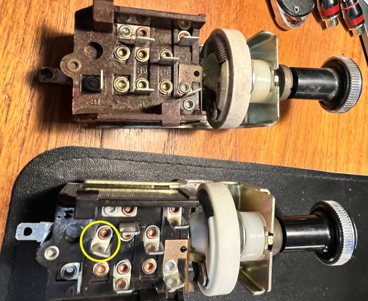
-
Turn Signal Indicator Stays On
NickyV replied to 1987Comanche's topic in MJ Tech: Modification and Repairs
@Silverhawk1991 Sorry it took me so long to reply to this. I did make a video! Hope this helps some people! -
Installing Tweeter Speakers On Comanche Help
NickyV replied to NEO auto's topic in MJ Tech: Modification and Repairs
I like to think of myself as an audiophile, although I'm by no means an expert. Also, I'm not made out of money. Over the years, I have inherited a lot of car audio components, including an two-channel Alpine amp and some 3 (or maybe 4)-inch midrange speakers. Over the past month, I surfed FB Marketplace, picked up a small sub and bought some better 6x9s (the ones that came from the PO were POS's). Because the Alpine was only two channel and I installed speakers in the doors a few years ago, I had to do some math-ing. I used Chat-GPT and figured out how to wire it all up using a combination of series and parallel. It sounded pretty good. But it was bugging me that the dash speakers were not the intended size. And because they weren't the intended size I wasn't able to mount them the way tweeters were intended to be mounted in the truck. Just today I went to the junk yard and found some Jensen tweeters in an 88 XJ. I took of that damn kick-plate AGAIN. (Man... I hate taking that thing off). I took the 3" full-range speakers out and put the tweeters in. I think it sounds pretty good! I did not use a crossover, but because I had done the series/parallel wiring, maybe I ended up wiring the system close to the way they did it in the factory? The tweeters are not overwhelmingly loud or tinny and overall, I think there's a bit more balance to the system. TL;DR — Tweeters under the dash with the factory brackets, 5" full-range speakers in the doors, full-range 6"9"s in behind the seats in the pillars, and a single 12" sub. I'll never be able to make the cab as quiet as a modern car, but now it doesn't really matter. Sound system sounds great! Ed Note: I am running a little bit of a crossover on the amp that is driving the tweeters and the full-range speakers. I am cutting the sub at about 80hz on the low end and the mids/highs at 100hz. I think that's right... I'm tired right now. But jazzed about my system. I think it's complete! -
What the heck is this thing? I took it out while doing some work, and I do plan to put it back in, but from what I can tell the only thing it does is direct air flow from a vent flap... and I'm hyperfixated on it because it's a weird design. Maybe it is intended to catch debris coming in from the outside? Also, if something like a hose is supposed to be hooked up to this, I don't think it has been for a long time.
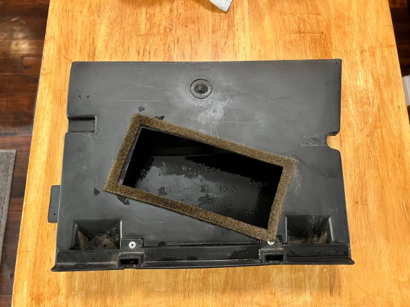
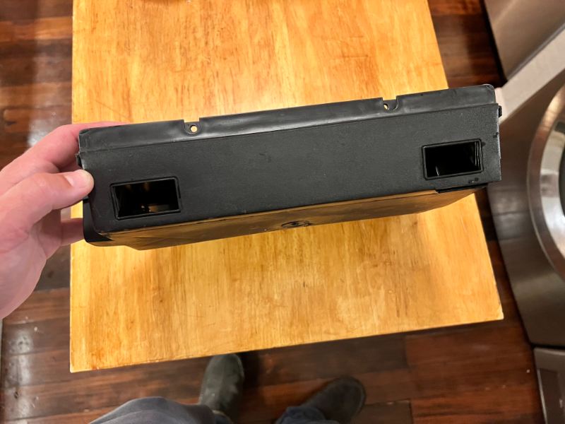
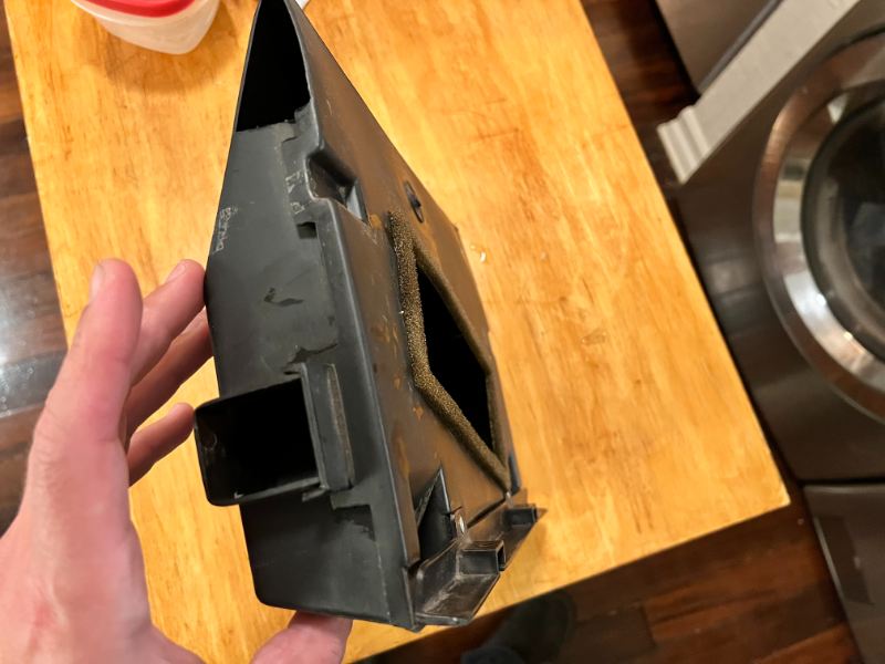
-
I'm looking for some advice. And this is something of a two-part question. I am planning to finally get the center brake light on my camper shell trailer working like it should. But I'd really like it to function as both a running light and a brake light — but avoid the issue of flashing. I understand from other posts that there are two methods to do this: Getting a logic module or bypassing the multifunction switch. But what I have been having trouble figuring out is if there is a best way to do this while also ensuring that the truck cap light functions like a running light and a brake light. When I search the web for logic modules, I'm not finding anything that clearly states they will provide this functionality. And come to think of it, I'm thinking I may have to do some additional cab-to-cap wiring if I want to go the bypass route: Running one wire for the running light circuit and another directly from the brake. Has anyone out there set up their third brake light so it works as a running light and a brake light? If so, how would you recommend I do mine?
-
Wire Over Driver's Shoulder Above Seatbelt?
NickyV replied to NickyV's topic in MJ Tech: Modification and Repairs
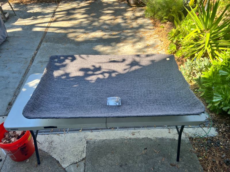
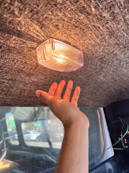
Thanks @pizzaman09! I'm so happy I did this. It's like... Night and day. Ha! But for real, I also replaced the halogen festoon bulbs with LED bulbs while I was doing all this. I gotta say... they are clearly brighter, but they didn't really make much of a difference in lighting up the cab. But with the dome light, I the whole cab is illuminated. I am trying to be as much of an OEM purist as I can be, but this dome light doesn't really look out of place to me. -
Wire Over Driver's Shoulder Above Seatbelt?
NickyV replied to NickyV's topic in MJ Tech: Modification and Repairs
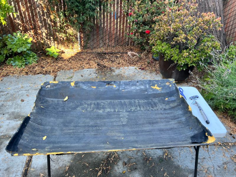
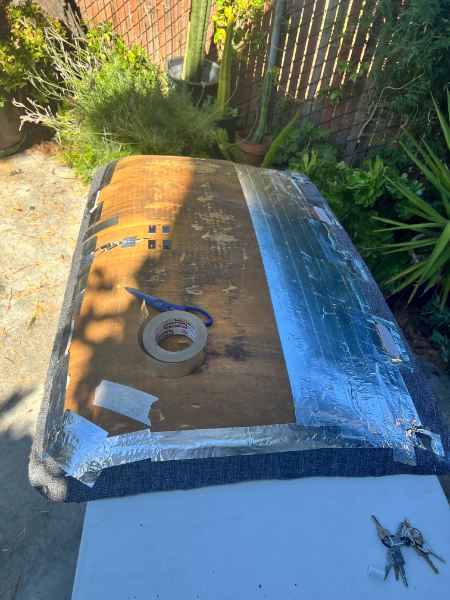
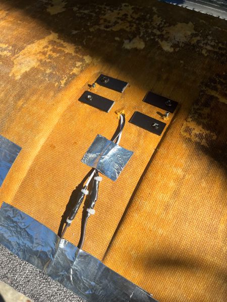
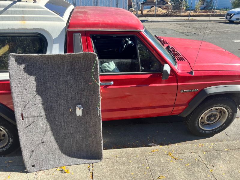
Thanks! That's what I was figuring. I got the headboard back in yesterday and hooked up my new dome light to the drivers side courtesy light. I also did a little work on my courtesy lights. I have the aftermarket Euramtec lights, which I purchased about 5 years ago. I put some LED bulbs in, but they are still not working perfectly. I don't know how I could possibly sand the interior parts and I didn't have the patience to go at them with a paper clip or dental pick. So I tried to bend the little prongs inward just a little bit and used a queue tip to brush a little dialectic grease on all the metal parts. Now one of them is working a bit better, but they are still kinda finicky. Next time I'm in there, I'll either just replace them with some brand new ones or I don't know what. Here are some pictures of my refurbished headliner. I'm pretty happy with it. I couldn't track down 3M-77 (big box store was out), so I bought what seemed to be the Gorilla Glue equivalent. Time will tell if I did a good job. But it looks good right now! I used an old blanket I had lying around.