

NickyV
-
Posts
149 -
Joined
-
Last visited
Content Type
Profiles
Forums
Gallery
Everything posted by NickyV
-

dimmer Dash Lights Work, but Dimmer Doesn't...
NickyV replied to NickyV's topic in MJ Tech: Modification and Repairs
@AnotherOldJeepGuy - To chime in on what @eaglescout526 and @gogmorgo have said: For me, it's been so far so good with the used switch I pulled out of an XJ. I actually pulled two out while I was at the yard. Once you get the hang of it, it's pretty easy, although you do have to get into a pretty awkward angle to yank it out. It's more difficult to get it in. That said, I haven't been monitoring the electrical flow out of the switch. I currently don't have a very sophisticated multimeter. (I need to get one... my old one broke). I just have a simple one that tells me if there is current and the voltage, so I'm not sure what's going on with resistance, etc. Anyway, the lights have been working now that I have the new switch. I also built myself a relay harness and created a really detailed post on that. So yeah, the switch is working well, and now that I have the new harness, I shouldn't be overloading it, which is great. But to the point about getting a brand new one, it seems like there are a lot of after-market solutions available through auto parts stores that would work just fine, and it would save you a trip to the junk yard. -
Thanks @89 MJ. I plan to stick around and do more write ups! I enjoy it!
-
Thanks for the additional input, @GonzoTheGreat. Sounds like I’m just gonna get a new seal. And go from there. Haha, @eaglescout526! I had to Google what NM stands for. So scientific! By the way… I just want to say that I love this forum! Every time I dip into one of the many XJ or YJ forums to research something, I see a bunch of one-sentence answers and rude responses to honest questions like “Let me Google that for you.” Y’all really care out here!
-
Thank you! I appreciate that!
-
Here's the fine print: "On models with plastic rocker arm covers, RTV or a gasket may be used. On models equipped with an aluminum rocker arm cover, RTV must be used. Later models use a pre-cured reusable gasket - install these without sealant." (Italics added by me). The page with the torque specs lists torque being 55-in-lbs for RTV and 44-in-lbs for the model with the built-in gasket.
-
Thank you again. I have the Haynes Manual and I think that it might use some different terminology than I've been using. It calls the valve cover the "rocker arm cover." I do not doubt your experience, I'm just trying to get on the same "page" as it were. It says "rocker arm cover-to-cylinder head bolts "55 in-lbs" with RTV. That's a lot more than you've recommended. Why do you think that is? Or am I looking at the wrong part? I don't see "valve cover" in the index of this manual.
-
Thanks, @eaglescout526. So, if I understand you correctly, you're recommending that I start by just replacing just the gasket on the VC I have? Honestly, I'm fine with keeping the plastic gasket. I just want it to work and to stop leaking oil!
-
Hello All, I've been researching valve cover replacements. I've still got a lot of research to do, but I'm wondering if anyone has had any good experiences with aftermarket VCs? I have a 1987 2.5L. Some of the posts about this topic are over 10 years old. In those, people tend to talk about finding a VC at the JY. But doing some searching on the old Googles, I'm seeing that Crown Automotive claims to offer an aluminum aftermarket solution. I really know nothing about this, but I'm a little worried it's too good to be true, especially because it costs less than $50 on Amazon: https://www.amazon.com/Crown-Automotive-33003857-Valve-Cover/dp/B008VPWLRG Any chance this might work? If not, what should I look for? Mine is currently leaking. Not badly, but I want to eventually fix it. Anything else I should be worried about? Like... if I've been driving it with a leaking VC for years and I suddenly seal that up tight, could it lead to other issues? I'd really hate to blow my head gasket. Then again, there's a high likelihood that my HG has never been replaced. Maybe it's only a matter of time.
-
What Minuit knows about stock Jeep radios
NickyV replied to Minuit's topic in MJ Tech: DIY Projects and Write-Ups
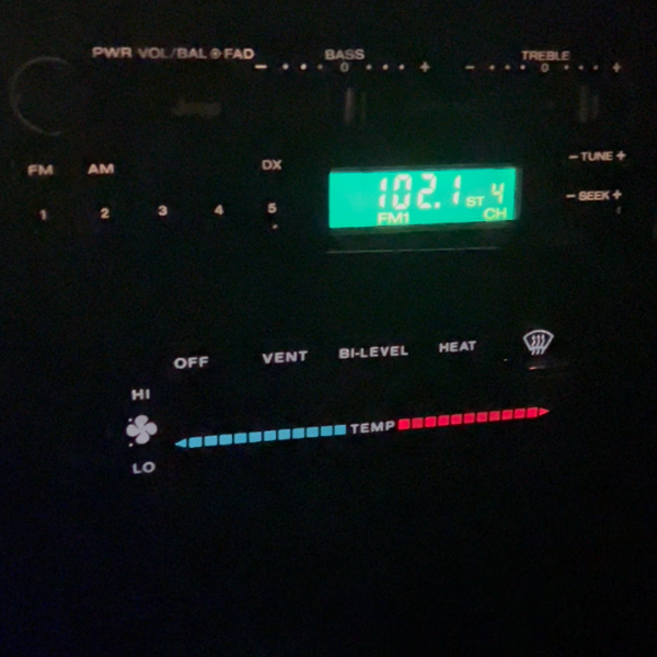
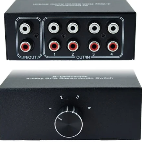
I'm deep in a phase of radio experimentation. A few weekends ago, I hooked up an AR-series radio (the radio-only kind with the sliding faders), and I hooked up an RCA channel selector out of sight, so I can switch easily between the radio and bluetooth. But I thought I could do better. Today, I found an RX-171 at the JY, and I follwed the video posted by @Pete M to perform one of @Minuit's "Science Projects." It is very easy to do. Per the video, I disconnected the AM band as well, and even repurposed an RCA cord I had lying around to hook up my bluetooth module to the radio. I'm going to drive around with it for a while, but I don't know if I will keep the set-up. The Pros: I really like the fact that I can control the volume of streaming media with the built-in radio knob, and adjust bass and treble and the signal from the bluetooth sounds great. The Cons: The reception on the radio is a bit fuzzy. I don't know if that is unique to the one I grabbed or not. Maybe it could be improved somehow by boosting the signal coming in from the antenna? Now that I have the confidence to repurpose RCA cables and tear apart radios, I am considering trying to do the same process with the the radio-only AR I have by tapping into the appropriate cables above the treble slider. The one thing I'm a bit wary about is that the two cables Minuit identified are from a slightly different model AR than I have. Has anyone tried the hack he described on page 3? Did it work? Also... it sounds like it will work a bit differently than the RX hack, in that it might not override the radio signal. Maybe a simple A/B switch mounted on the dash would do the trick. Or I could just use the RCA channel selector I already have hooked up. Hmm... If I succeed in this next science project, I may offer up the other radio with aux in the classified. -
Parking brake pedal not staying engaged
NickyV replied to Warren99's topic in MJ Tech: Modification and Repairs
Thanks @Eagle_SX4 Interesting update. Last night I was fiddling with my brake a bunch. Just trying to get a better understanding of all the parts. It started locking a lot more consistently. I realized that for the past several years, the footwell kickpanel has been missing, which would have allowed for additional lateral movement. Right now, if I'm deliberate about it, I can get the parking brake to engage. Haven't tried it on a steep hill yet... I still think that I need to do some kind of fix, but I'm happy about this development for the short term. -
Can We Talk About Radios?… Again?
NickyV replied to neohic's topic in MJ Tech: Modification and Repairs
Interesting... -
Can We Talk About Radios?… Again?
NickyV replied to neohic's topic in MJ Tech: Modification and Repairs
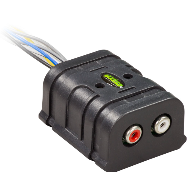
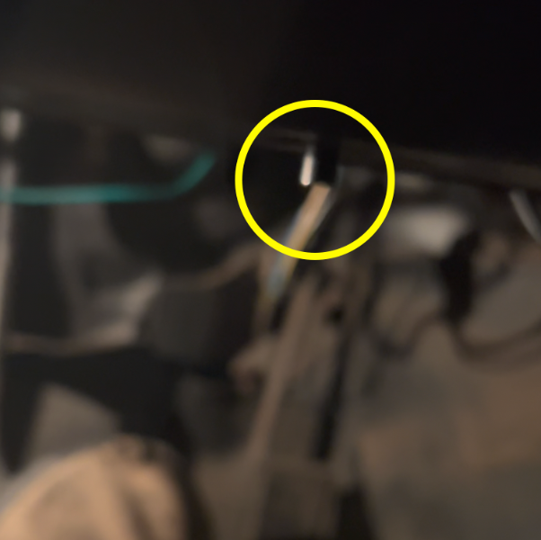
For the purposes of inspiration, here's V 1.0 (I didn't like this, but maybe someone who is much savvier with electronics could get a Jeep faceplate to control a more modern stereo? This "faceplate" was from one of the RX series with a tape deck: And here is how I rigged up V 2.0: I got this working radio. I believe it's one of the AR series. I hooked it up to a line converter which, come to think of it... I hope I grounded this... I must have. I don't think it would work if I hadn't. And I tucked this up under the dash. I still need to secure it. Then I got something like this. (Note, this is not the exact one.) The one I have has a the knob running perpendicular to the RCA ports. I have found push-button versions of this. Basically an A/B switch that I think I might be able to mount on the dash in one of the factor switch positions. I removed the big knob and the post that the knob sits on was long enough to fit through one of the holes for the cruise control. It was more complicated than that... I had to remove the metal housing and do a few more things, but hopefully this gives you a sufficient picture. I mean, this is a horrible picture that I grabbed as a screenshot from a video, but you can see the little post/knob. That is what I twist to switch between the radio and the bluetooth inputs.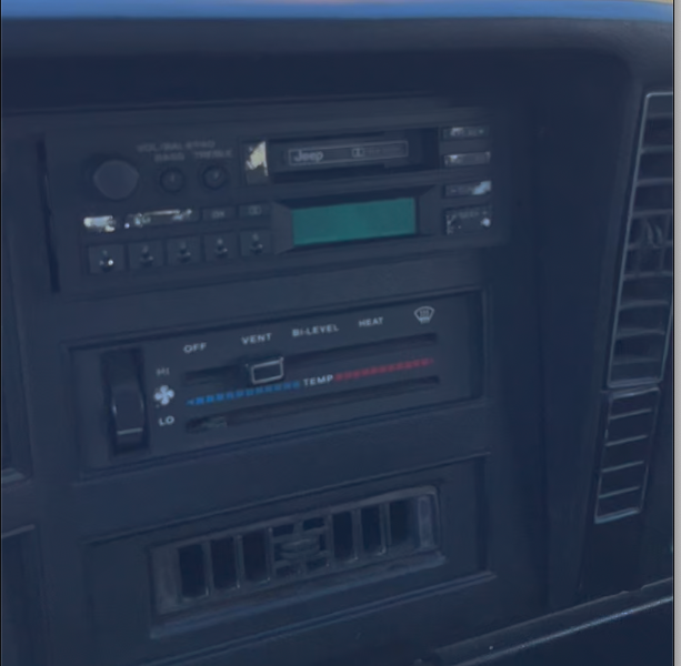
-
Can We Talk About Radios?… Again?
NickyV replied to neohic's topic in MJ Tech: Modification and Repairs
Looks like you're correct. There are holes down there for mounting the box, which is yellow with an AMC sticker on it. For my current solution, I took -
Can We Talk About Radios?… Again?
NickyV replied to neohic's topic in MJ Tech: Modification and Repairs
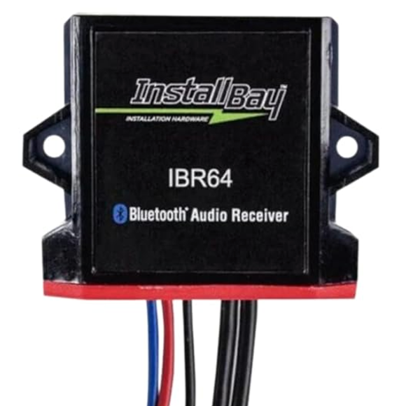
I've tried two different options in the past month. I had a factory radio with tape deck that sat in my basement for years. When I finally tried to hook it up, it didn't work. Super frustrating. I removed the faceplate and crammed a smaller Dual radio way back in the space where the radio goes. Then I used magnets to have a faux OEM faceplate. It looked pretty convincing, but it was not very functional. I've since moved onto my current setup, which is a working stock radio from a '91 XJ. I also have a bluetooth module tucked up under the dash. I switch between them with an RCA channel selector that I mounted under kick plate beneath the steering wheel. I took advantage of some holes that were already there for some option that I don't even think any MJ comes with... a yellow box that I've seen on XJs at the junk yard with an AMC sticker on it. This current setup all looks pretty slick and era appropriate. Only issue is I'm starting to think the radio I pulled from the XJ has a bad ground. I'm running all of this through a pair of amps behind the bench seat. One is for the single 12" sub and the other is for all the mids and highs. When I'm streaming from the phone it sounds damn good. When the radio is playing it also sounds pretty darn good. But when the volume is low, I'm getting the thing where I can hear a high pitch whine that increases with acceleration. I know it's gotta be a ground issue. But the thing is, when I had the Dual crammed behind the faux faceplate, I wouldn't get the whine with either the radio or the bluetooth, which has me thinking the bad ground is in the new/old, functional factory stereo. I could have screwed something up when I put the new radio in, I suppose. -
Parking brake pedal not staying engaged
NickyV replied to Warren99's topic in MJ Tech: Modification and Repairs
I think I have read just about every thread on here about the parking brake and fixes. The DIY E-Brake Fix, Parking Brake Pedal Refurb, and New Parking Brake Fix are all great. I want to start with the low hanging fruit and I've got a couple questions: Is the fix described in this thread (tightening down the main pin, the catch lever pin, and putting in a new spring) generally accepted as the first thing to try? Can I tighten the pin without removing the entire assembly? How do you tighten the pin? Do you apply a bunch of pressure to either end of the pin? I'm having trouble understanding how this works. Does the pin get compressed? Here are the symptoms on my e-brake. Keep in mind that I have not removed it to get a good look. Lateral movement of the e-brake pedal Some teeth seem to catch better than others (maybe some are rounded or broken?) Not sure if this is a "symptom" but the e-brake doesn't hold all that well unless I get it to catch with the pedal almost all the way against the floorboard. Should it be holding firm without pressing it all the way down, and if so, does this mean I need to shorten the cable a little bit? I am planning to just try to get a new spring on there first to see if that helps. I really like the idea of doing a complete refurb, but I don't have all the tools outlined in the two main threads easily available. I would eventually like to have a drill press and some kind of welding torch, but not sure I'm ready to buy those things for just one project. -
Build Your Own Harness: A Step-By-Step Guide
NickyV replied to NickyV's topic in MJ Tech: DIY Projects and Write-Ups
Thanks for the response and your thoughts on this project, @gogmorgo. This forum and YouTube make projects like these way more approachable than they would have been before, but one thing I find challenging is figuring out the right search terms. Just knowing the term "relay pigtail" would have been helpful for me to find the part that I wished I had — the one in your picture. I live in the Bay Area/Northern California and I don't have to worry about salt on the roads and ice. Hopefully my shovel connections will hold up for some time. But I will make a note of this and I may eventually upgrade. It would be nice to have everything sealed up real tight. I'm also glad you brought up the relays with the 87a terminal. I actually used one of those, because while I apparently have the patience to build a harness myself, I don't have the patience to order parts on the internet when I'm rearing to go on a project. As it happens, one of the relays I bought is a standard relay (30, 85, 86, 87) and the other is one with an 87a (because that's what they had at the auto store when I went to get my relays). I just left the 87a empty. But I think I used it for the high beams. At some point in the future, I may figure out how to make it so my fog lights go off when high beams are on. Then again, I've never actually used them while on the road. This is not a daily driver and I keep the covers on them most of the year... occasionally pulling them off just to make sure they are still working. I kinda feel like the only time I'd actually use them would be on a forest service road, far away from the prying eyes of the CHP. -
Wow... Add this EQ to the wish list. Wonder if I'll ever be able to find one in working condition. It's so cool that it has a pair of memory slots. This would be ideal for going between music and news/audio books. I recently installed some Jensen tweeters I found in the JY. They work and they are not overpowering as some in other threads have warned about... at least they aren't overpowering to my ear when listening to music. However, when I switch over to news radio or play a book on tape through my recently-added Bluetooth module, it can start to get a bit grating depending on the timbre and vocal qualities of the narrator. I was listening to one the other day where the "S" sounds were starting to give me a headache. On the iPhone, the EQ settings are kind of buried. I wonder if I could set up something using Shortcuts for when I'm using it to listen to podcasts and books on tape... Hmmm...
-
Build Your Own Harness: A Step-By-Step Guide
NickyV replied to NickyV's topic in MJ Tech: DIY Projects and Write-Ups
Huh... Thanks for letting me know about these, @89 MJ. I literally didn't know they existed. I mean... some of the butt connectors I have are probably actually just this. Wish I'd realized that. Will keep in mind for the future! -
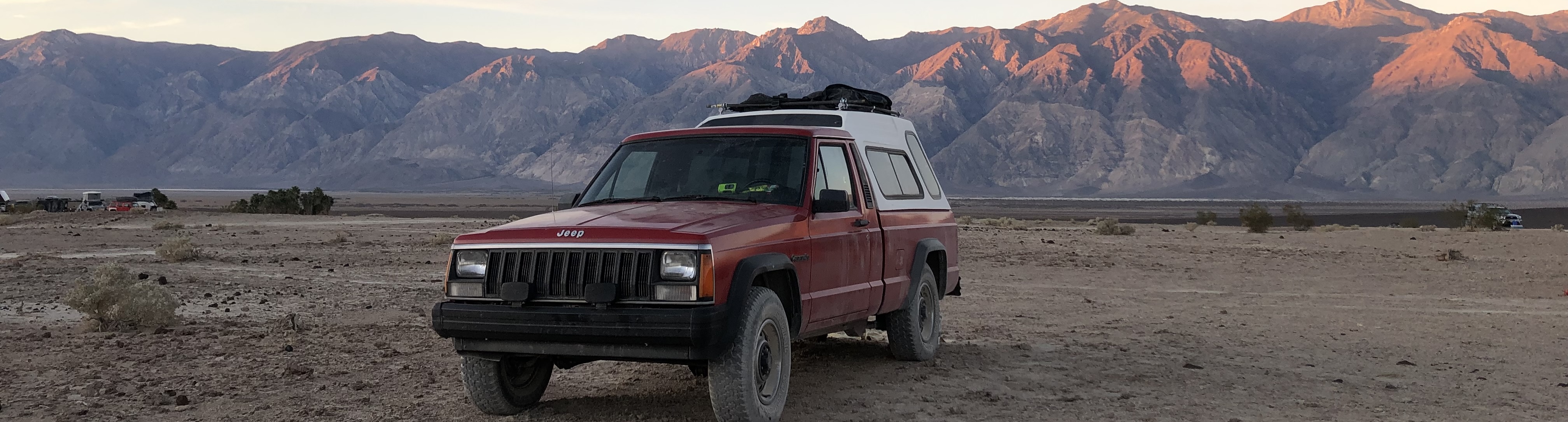
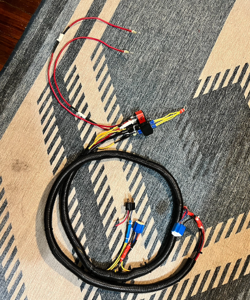
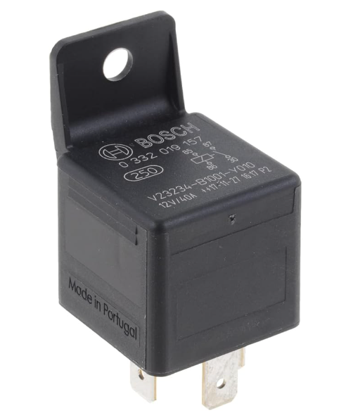
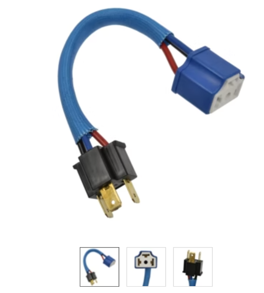
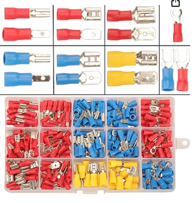
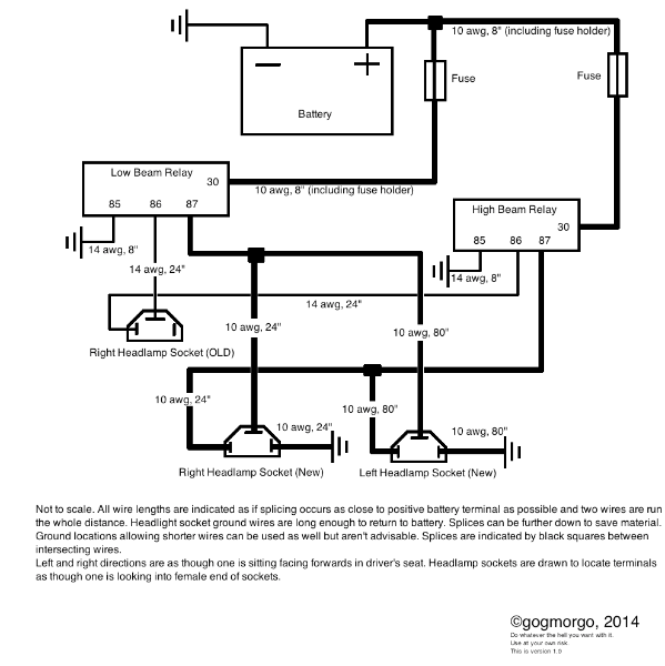
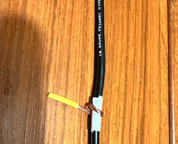
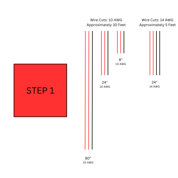
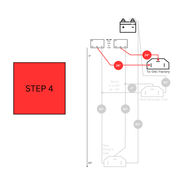
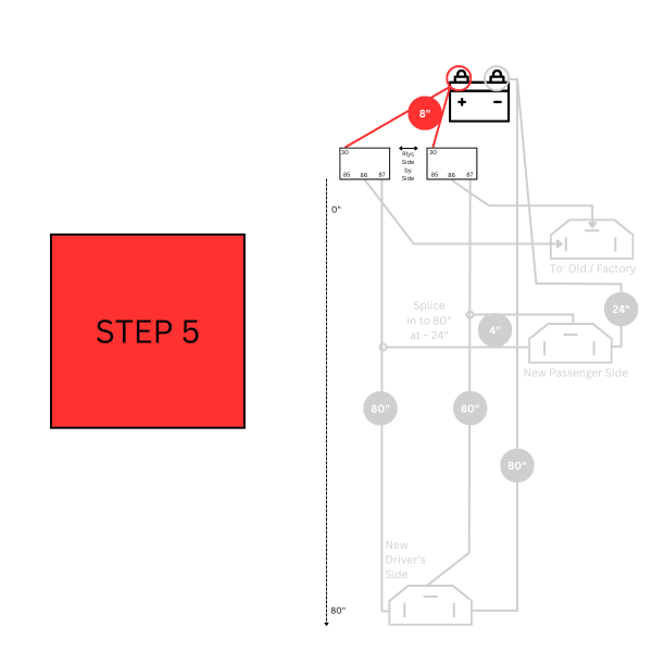
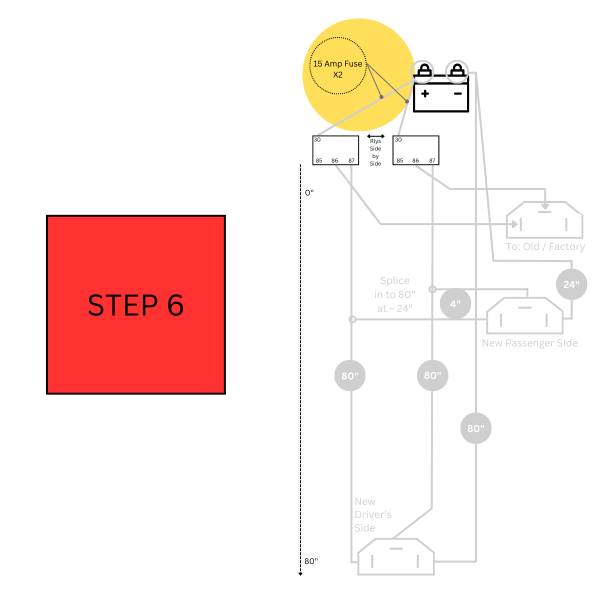
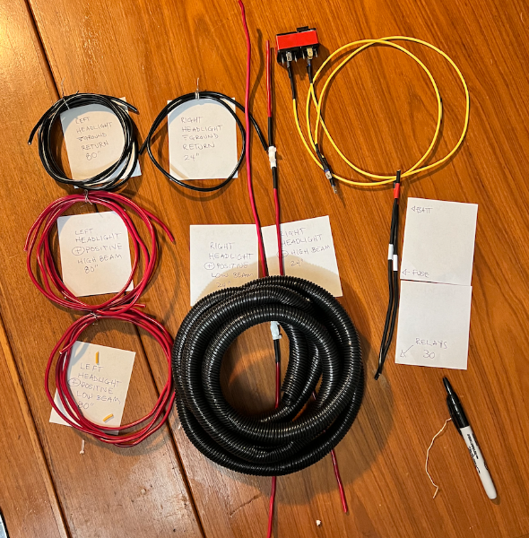
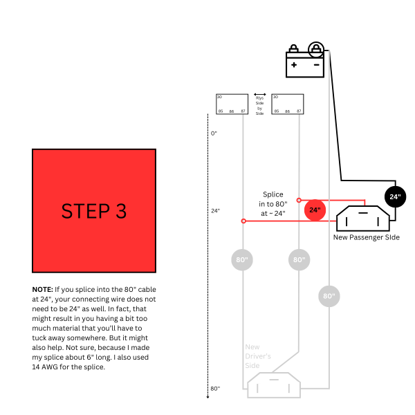
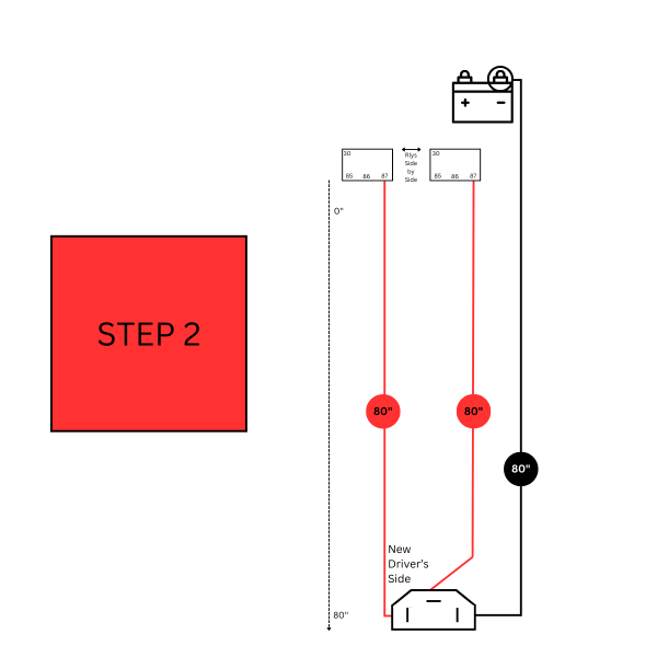
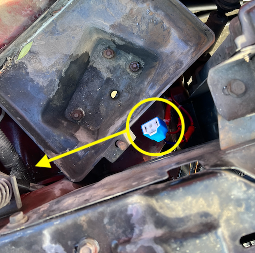
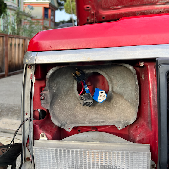
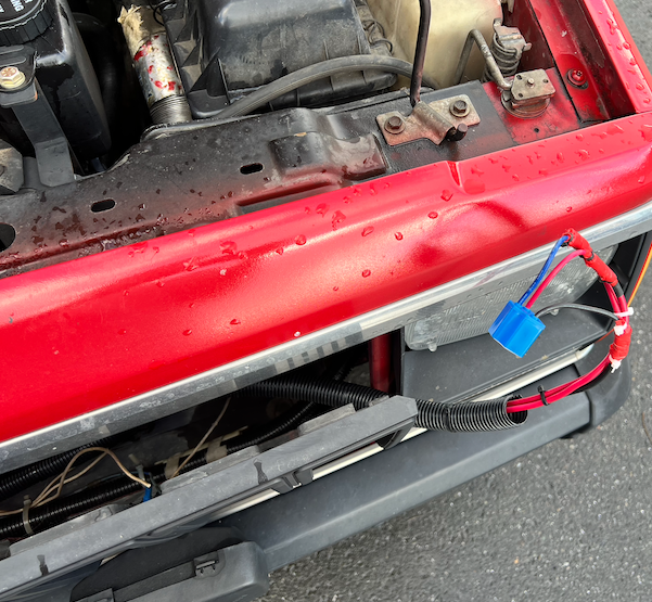
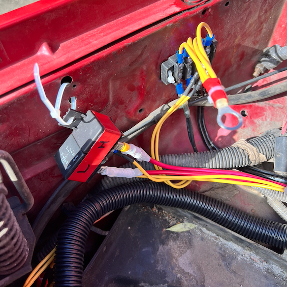
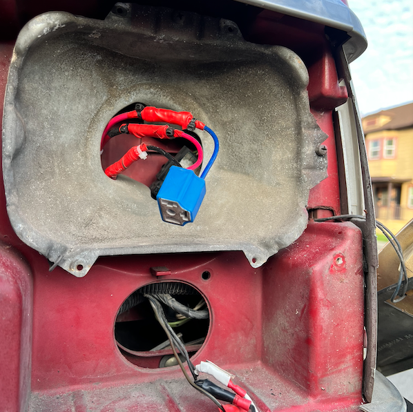
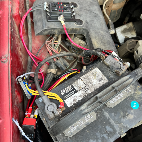
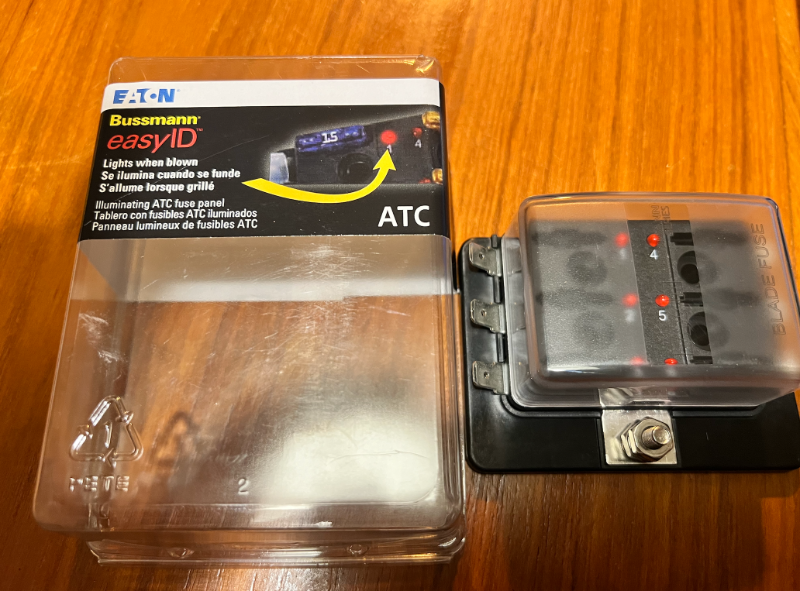
Greetings, Fellow Comanche Enthusiasts! I’ve spent the past few months diving into projects on my 1987 2.5L, 2WD, Short Bed, and this forum has been an invaluable resource. I’ve really enjoyed the time I get to spend just working with my hands and not thinking about emails I have to send. But it occurs to me that I’ve spent a lot of time asking you all questions. I want to give back with a tutorial of my own. I’m much newer to this than many of you, so I welcome any notes on things I could have done better or things I’ve done flat-out wrong. I’m going to write a step-by-step guide on how I built a Headlight Harness Upgrade using @gogmorgo’s diagram. And I’m going to add some diagrams of my own. I hope this ends up helping someone else down the line. NOTE: This is a LONG write up. If you know what you're doing, I suggest taking a look at the diagram below and then the step by step slide show I have at the end. Step 1: Assemble the Materials The first thing I did was add up the total length of 10 AWG and 14 AWG wire that the diagram calls for. The following list turned out to be a little more than I needed, so I think it’s the perfect amount. WIRE: 10 AWG: 30 Feet or 360 Inches 14 AWG: 16 + 48 = 5 Feet or 60 Inches RELAYS: Two 30-amp headlight relays with the following connections: 30, 85, 86, and 87. Here's an example. This one is 40 amps, but you get my drift. H4 HEADLAMP SOCKETS: I scratched my head on this one for a while, because I was unfamiliar with it. Also, all the auto parts websites have my vehicle information by now and they were telling me certain headlights didn’t fit my MJ. I turned off the vehicle-specific search function when I was searching and that helped open up the results. I ultimately went with this one, because it was available locally and the connector was ceramic, which I’ve heard is better than plastic. Makes sense when high temperatures are in play, right? I also wanted to use the male end of one of them to make the connector for the existing OEM harness (see the second picture). OTHER MATERIALS: I had most everything else I needed already, but you’re going to need things like wire strippers/crimpers, big box of wire terminal attachments, a ton of zip ties, and electrical tape. Some other nice-to-haves are a soldering iron, heat shrink wrap, a heat gun, and other electrical components like that. Step 2: Plan Your Build I’ve charged headlong into way too many projects. And honestly, I could have taken more time with this one. But with a project like this, it really helps me to lay everything out in front of me. I looked at @gogmorgo's plans over and over again and cut most of my wire to length before I did anything else. I also labeled my lengths of wire and cross referenced them with the drawings to see if it all made sense. One thing I wish I had done was also plan what kinds of terminal heads I was going to use at each juncture. Doing this would have saved me some time down the line. Step 3: Slow and Steady (Learn From My Mistakes) If you’re brand new, or relatively new (like me), don’t get flustered. Take your time. Like Gogmorgo says, the diagram is not to scale, and it can be hard to visualize at first. Here are some things that took a little while to click for me: Your relays are going to be right next to one another and very close to the battery. Once the new harness is built it will form the shape of a capital “L” — running from the battery on the passenger side of the engine bay, down to the passenger side headlight, then to the driver's side headlight. The short length of the “L” runs from the battery to the passenger side headlight. The long length of the “L” runs from the passenger headlight to the driver’s side headlight. All of the 24-inch lengths of wire correspond to connections at the passenger side headlight. All of the 80-inch lengths of wire correspond to connections as the driver’s side headlight. If you do it like I did, you will have to do at least two splices. These will go on the positive lines. There were two ways I considered doing this. One way would be to connect the positive lines directly to the shovel terminal that attaches to the 87 terminal prongs on each of the two relays (high and low beam). Doing it this way will require the full 24-inches of wire. You may also need to get creative with how you connect the two ends of 10AWG wire to the shovel. Another way is to splice the shorter length of wire roughly at the right angle of the “L” shape that this harness will form when it is installed. Doing it this way will allow you to save a little bit of wire. This second way is the way that I did it. You do not need to splice any of the ground wiring. You do not need to splice the battery-to-relay wiring. Instead, you can just make two 8-inch lengths of wire. On one end attach them to the battery. In the middle, place your in-line fuses. On the other end place a shovel terminal connector to attach to the 30 prong on each relay. If you end up using a left over male H4 connector, remember to connect your wires as a mirror image of the diagram above. I made a mistake here and didn't discover it until the harness was installed. I had to strip wires and make some new connections while crouching at headlight level. Not fun. If you notice, in the picture above, there is a short length of red wire that isn't connected to anything. But that SHOULD have been connected to the high beam relay. Which leads me to No. 7: If you notice in the diagram above, both high beam connections are on the left hand side of the female connector and all the low beam connections are on the top of the female connector. Remember that! Step 4: Splicing & Dicing I was practically brand new to splicing when I started this project. I am also very bad at soldering, and I don’t have a great soldering iron. Here’s how I ultimately spliced the positive cables together: Cut out a very small segment of the 80-inch positive wire. You can use the wire cutters to make the first two cuts around the outer edge of the wire. Then you’ll need a razor blade to cut from one of those cuts to the other cut. Then you’ll peel the slim piece of wire covering off, as if it were a bandage wrapped around your finger. The location of this splice is very close to the connection point for the passenger side headlight connection. The connectors I used came with 14 AWG wires attached to them. I thought about devising a way to maintain 10 AWG all the way to the headlight connection, but I abandoned that idea, and it was helpful to do so. That’s because it was way easier to wrap 14AWG around the exposed splice point of the 10 AWG wire than it would be to wrap the very thick 10 AWG wire around another 10 AWG wire. I took this picture to help you visualize the process. Picture the white electrical tape as the exposed bit on the 10 AWG wire. The yellow bit is 14 AWG wrapped around the exposed portion. Use a soldering iron or thin strips of electrical tape to help secure it in place. As I said, you’ll need to do this on both lengths of 80-inch wire. Step 5: Making Connections Now it’s time to put it all together. For this bit, I made some diagrams of my own. Red is for positive connections. Black is for negative/ground. Connect all the shovel terminals to the wires going to the relays. Connect the new headlight sockets to the wires. Prepare your connection for the existing OEM plug (female plug on the passenger side). I found it helpful to use zip ties to fasten the longer lengths of cable together as I went along. This helped prevent tangles. When I was done, I covered the whole thing in conduit, which I think was helpful when installing in the MJ. MAKE YOUR CUTS MAKE THE DRIVER'S SIDE CONNECTIONS MAKE THE PASSENGER SIDE CONNECTIONS MAKE THE CONNECTIONS FOR THE FACTORY PLUG MAKE YOUR BATTERY CONNECTIONS MAKE AN INLINE FUSE ON THE BATTERY CONNECTIONS Step 6: Hook it Up! I could probably write a whole tutorial on how to do this as well. It took me a long time and I hit some road blocks along the way. Thankfully there is a detailed installation video from K Suspension that you can watch here. The main difference with the harness in this video is that the grounds do not run all the way back to the battery. I opted to create a harness where the grounds return all the way to the battery, because I hoped that would lead to a healthier circuit. By the way, if you don't want to take the time to build your own, or don't feel comfortable doing it, K Suspension and many other companies make this exact harness. Some of them are even cheaper than what it would cost you in money and your valuable time to do it DIY style. But, at least for me, tinkering is part of the fun! Step 6.1: Hook it Up! (Pt. II) OK... Just thought I'd add a few more pics of the actual install. I didn't document this process perfectly. But here goes: It helps to take the batter out completely. This is also good because you know you won't accidentally create a short while the harness is flopping around. This picture is of when I was thinking I'd snake the harness underneath the driver's side of the battery tray, but you'll actually want to snake it under the passenger/fender side. It's a tighter squeeze, but a more optimal flow. Bring the passenger side connections into the passenger headlight bucket. In this image you see the new male connector, the new female connector, and the old factory female connector (clockwise from top). Bring the driver's side connection over to the driver's side bucket, snaking it along behind the grille. I don't have AC (yet). There was a lot of space back there for me. Bring the new driver's side connection into the driver's side headlight bucket. FYI, getting these connections into the buckets was one of the hardest parts of this — at least physically. It's a real contortion act. Be patient. Wear gloves or be prepared to slice up your hands. I also ended up taking out the turn signal on this side. Not sure I needed to, but I got stuck for a while on this step and I wanted a better view. Figure out where you will place your relays. In this picture, you can see where I chose to put my relay and where I decided to put my negative/ground terminal connection. You can use sheet metal screws, but I used zip ties. I might change that in the future. There were many holes already drilled on the interior side of the passenger fender on my '87, which made this pretty easy. Put it all back together. Don't judge me! I need to clean up my battery and replace cables and all that. It's on my list. Anyway, here is the only picture I have in this entire thread of my inline fuses. The fuse block at the top of the pic has a transparent plastic cover, which is good. I will eventually find a better, cleaner way to mount all this stuff, but this is working for now. All right! I think that is it on this now. Se you all in the comments!
-
Headlight Wiring Harness Questions
NickyV replied to SBpunk's topic in MJ Tech: Modification and Repairs
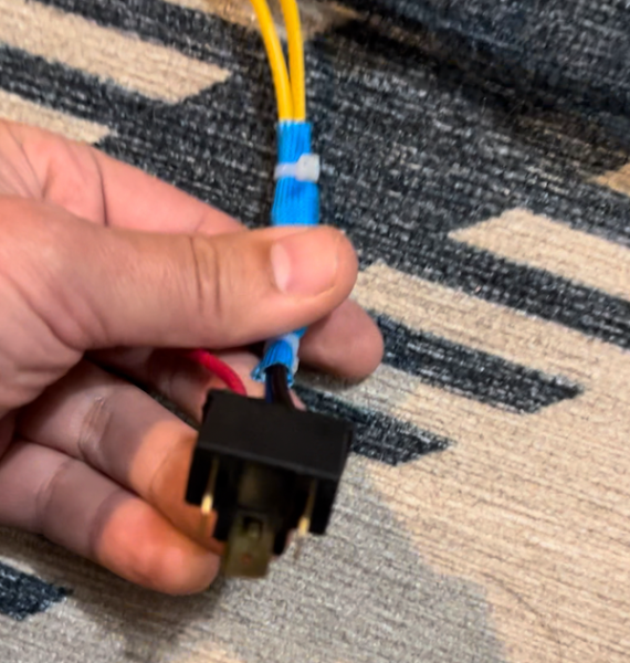
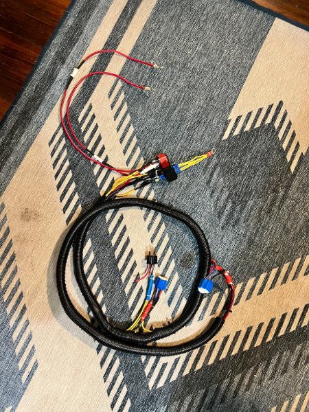
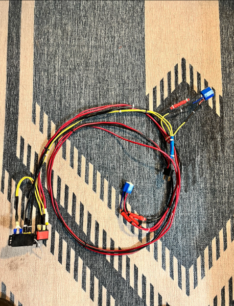
Thanks @schardein. I'm attaching a pic of the fuse terminal I picked up the other day, which I was thinking about returning. It has six terminals. I was thinking that I could use it for a handful of the additional accessories I'm running off my battery, but then I saw 20 amp max and it seemed like people here were recommending 30 amp relays, so I thought this didn't have the capabilities I needed. Maybe I'm wrong about that. (Edit: I would not be surprised in the least if I'm wrong about that.) In addition to the fuse terminal, I'm also going to attach the pics of the harness I've put together. I'm glad to see that some people are saying they paid close to $100 for a high quality one, because that's about what I spent on all the components, and I don't even want to talk about the labor I put into this. Lol. The pictures of the harness have everything except the fuses, which need to go somewhere along the two shorter red cables with the ring tips. I know I can also do inline fuses. I need to go back through this thread and read what some have said about what the fuse should be, but if someone cares to tell me here, that'd be great too!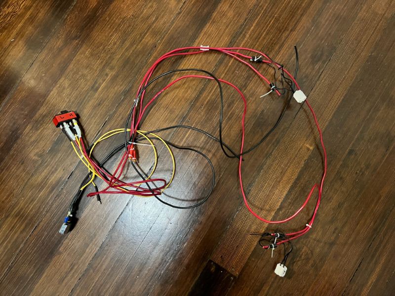
-
Death wobble is trying to come back
NickyV replied to Knucklehead97's topic in MJ Tech: Modification and Repairs
Thanks, @MississippiComanche At this point, I do not have plans to lift the truck. The most "off-roading" I ever do is driving on forest service roads to get to campgrounds, and I've always had sufficient clearance for that. I'm realizing whenever I see conversations about track bars, it usually has to do with a lift. I'm assuming I have a track bar as well, even though it isn't lifted. (Novice question, I know.) What's a good track bar for a non-lifted, 2WD MJ? One day, I want to get 4x4, but it will be a while. -
Death wobble is trying to come back
NickyV replied to Knucklehead97's topic in MJ Tech: Modification and Repairs
Track bar and spicier ball joints! Love it! @MississippiComanche, what tires did you get? Your signature doesn’t mention a lift. Is your MJ lifted? -
Headlight Wiring Harness Questions
NickyV replied to SBpunk's topic in MJ Tech: Modification and Repairs
I am late to this thread and others about headlight harness upgrades. I made a lot of progress last night building my own upgrade. I stopped because it was late and because I want to do this right. I’m following @gogmorgo’s diagram, and I’m trying to do it with minimal splicing and grounds going all the way back to the negative terminal on the battery (or more specifically to a terminal block connected directly to the negative terminal). Some questions I have: 1) What do people recommend for the new headlight plugs? Direct links or part numbers + brands are helpful. 2) What do people recommend for the relays? Same request with links/part numbers/brands. 3) I already have two crimp-on terminal connectors bolted to the positive terminal of my battery and I think it is time to upgrade to a more elegant solution. I’m hoping for a terminal bank with ports. I picked one up at AutoZone last night but didn’t read the package closely. Each terminal is a max of 20 amps. That seems like it won’t do. Anyone have a positive side terminal bank that they like? Thanks! -
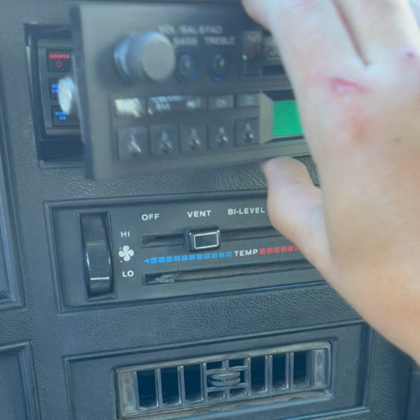
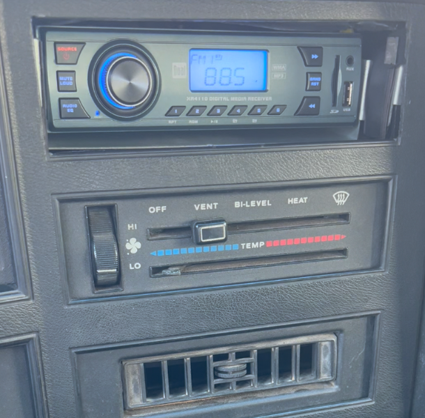
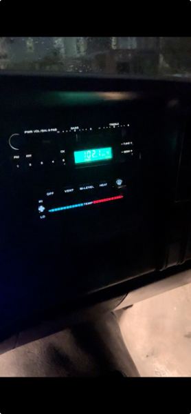
UPDATE: Success! I got the damn thing in. After moving the clock plate out of the way it was still giving me trouble, but I think I figured out the issue. The part of the bracket that attaches to the radio (male?) did not want to fully lock into place on the receiving bracket under the dash. I was wiggling and trying all kinds of things. Then, I accidentally applied some downward pressure on the top of the bracket while I was pushing and it went in. I ended up having to take the radio out once more and when I put it in again, I did the same thing. I think by applying a little pressure I shifted the hook on the bracket just enough to go into place. Maybe it's designed that way? Not sure. But now I have yet another question. The display looks great when the running lights or headlights are on. But when they are off, I can't make out the dial (even in the daytime). I wonder if this is just because the unit is old or if maybe there is a setting I can access by pressing down buttons and twiddling knobs.
-
Death wobble is trying to come back
NickyV replied to Knucklehead97's topic in MJ Tech: Modification and Repairs
Hey! I like that idea, @schardein! Not that I'm trying to be a cheapskate with my personal safety. Heh...