


NickInTimeFilms
-
Posts
27 -
Joined
-
Last visited
Content Type
Profiles
Forums
Gallery
Everything posted by NickInTimeFilms
-
This makes me wonder if your engine would have tried to start if you unplugged the distributor sync sensor before the re-index. Maybe if the ECU can't match the cam to crank then it won't attempt to fire. I may suggest this in the future for troubleshooting.
-
To dive a little deeper, the ECU reports the time gap between spark commands, which through some math we can find the engine RPM from. If there is an RPM reading to show, that means the ECU is sending spark. No RPM, No spark commands. So if you are getting an RPM reading but no spark, then I would look into the ICM, coil, or distributor and plugs. The thing to take away is that RPM isn't a direct reading from the CPS, but rather the aftermath of the ECU processing the CPS and giving the ok to send spark. I wish the ECU atleast sent an OK flag when CPS signal is sufficient, but they really dropped the ball in that area of reporting.
-
For all the info available from the ECU, it's rather lacking when it comes to anything directly involved with the CPS. The REM is starting from the end, rather then the beginning of the chain so it's still difficult to pinpoint the CPS for sure. All that code really tells you is that the ECU is not sending a spark command to the ICM, but this could be caused from multiple reasons, not just dead CPS. Knowing exactly why the ECU isn't deciding to send spark has still been a mystery to me beyond a weak CPS signal so it's just written like that for now.
-

REM installed and seeking translations
NickInTimeFilms replied to NC Tom's topic in MJ Tech: Modification and Repairs
Figure i'd chime in. First thing I'm noticing is your vacuum at idle which is really low, but maybe that has a bit to do with the low idle. Check your map vac line is clean and tight in the lower TB port. The IAC reading showing 1 is odd though as that should be indicating that the ECU is continually trying to lower the idle even though it's already low. TPS is a little low but not the end of the world. adjusting it and resetting the ecu may help a little, or at least feel like it till the ecu relearns the fuel trims. Speaking of, LT fuel trim is a tad low which sounds like it's running richer than usual, and showing by the o2 sensor i'd say that i'd agree. It's not holding closed loop so it may be too rich to even correct for. Do you have aftermarket injectors? -
All I want for Christmas is ...
NickInTimeFilms replied to NC Tom's topic in MJ Tech: Modification and Repairs
Best spot is one of the firewall grommets by the steering column, then up and over the map sensor. -
All I want for Christmas is ...
NickInTimeFilms replied to NC Tom's topic in MJ Tech: Modification and Repairs
Sorry about the lag, parenthood has been dragging me through the ringer this last month. The website link earlier explains the readings that aren't on the booklet, but I didn't think to add the more spelled out ones from the Readings menu. Finally got to watch the video, and I see the confusion. The clock panel definitely isn't the "easy" model to use by the odd button layout as you can tell. But as requested, I've attached a picture of how the buttons are mapped to the screen. The positions never change so you can trust what's top or bottom. Sounds like you got the Gauge screen figured out, but each of the 4 corners have their own loop of the same data cycle. So you can use any corner to click through the entire set of data. As far as the data I saw, nothing major stuck out to me. The only problem child I saw was your IAC Turns reading showed < 0 which means the ECU was continuously trying to lower the idle but was unsuccessful with the IAC. The odd thing about this is your idle RPM was under 700 so I'm not sure why it wanted to go lower. Usually that kind of reading means your IAC is stuck, leaking, or you have other vacuum leaks that the IAC can't adjust out. You o2 sensor was swinging nicely, and your ST Short Term Fuel Trims looks great, nearly right on target. Good news for healthy closed loop. TPS reading was a little low at 12% when 17% is the norm, but it's almost not worth adjusting for such a little offset. If you do decided to dig into this, pull the battery cables once you're done to reset the ECU so it doesn't try to idle funny on you. Not sure if you were holding the brake for that entire video, but if you weren't then the TCU brake switch needs to be adjusted as it's not making contact with the pedal lever anymore. All this affects is torque converter lockup on the highway though. I know that doesn't answer your hard start or lumpy idle, but what I can say is that it's probably not sensor related as everything seems to be reading nicely. That means it might be more mechanical which requires the hands on kind of diagnosing. If you want, open up the No-Start Test and record it when you're having a hard time starting. That can help us narrow down what's missing sensor wise at least.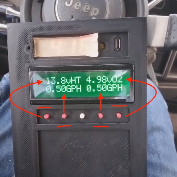
-
All I want for Christmas is ...
NickInTimeFilms replied to NC Tom's topic in MJ Tech: Modification and Repairs
I'm definitely trying to fit way more onto a 16x2 screen then I should be which leads to complex and incomplete menus like the No-Start. The video you posted is mirrored which will make for some tough watching, but regardless I am absolutely excited to watch you try and figure out the menus. That kind of stuff tremendously helps me make better and easier to use software. I will however have to watch it possibly in the next few days as my flight is tomorrow and I still need to pack. UPDATE: I was able to rip it from Youtube and flip it on my computer at least. -
All I want for Christmas is ...
NickInTimeFilms replied to NC Tom's topic in MJ Tech: Modification and Repairs
Home > Diagnose > Tests > Engine No-Start. The 2nd line of gibberish is the first letter of each test. They will disappear one by one as they pass so whatever is left is a possible issue. Scroll down to see full text of each remaining issue. I think I have a V0.9 software walkthrough, but I need to get full documentation together. If we ask enough questions here then we can just make this the wiki . -
All I want for Christmas is ...
NickInTimeFilms replied to NC Tom's topic in MJ Tech: Modification and Repairs
I know you're fighting a no-start, but all I can say is be careful with the readings you get when the engine is off. The Renix data definitely has a few quarks to learn so you aren't chasing your tail on data that doesn't update or display right. One example is the o2 sensor, it does not correctly report unless running. Another is that ECU Voltage will show 0v unless running. I try to make notes of anything odd on my updated readouts summary page here: https://nickintimedesign.com/rem-gauge-readouts/ Maybe while I'm away I can push myself to make some fuller documentation about the more hidden features of the REM. On the Diagnose Screen there are a few different views you can access. - Top Left is the Info option. Clicking this will cycle through a few little notes about each sensor. - Bottom Left is the Mode option. Clicking through this will cycle a few tracking options, such as detailed info, sensor Min/Max, and sensor graphing. Note: While the Min/Max view is up, the i button will change to r for Reset, incase you want to reset the min/max reading for that sensor. As for the dummy lights, nothing useful there since o2 is inaccurate when engine is off. The datastream looks a little goofed since the ST fuel trim isn't 128 even though it's in Open loop. Try clicking over to Sensor Tests > No-Start Tester and see what still remains after a crank. I'm betting it'll probably say CPS, but that doesn't exactly mean the CPS is dead, just that the ECU is not sending a spark signal to ICM yet. -
All I want for Christmas is ...
NickInTimeFilms replied to NC Tom's topic in MJ Tech: Modification and Repairs
Let us know what data you find! As for the sanding, best of luck. These 3D printers are a constant chore to keep dialed in and pretty. Some tips I can give are that Acetone vapor can help smooth the ABS plastic, and Super Glue works wonders if anything ever snaps. The glued joint will be even stronger than before. -
All I want for Christmas is ...
NickInTimeFilms replied to NC Tom's topic in MJ Tech: Modification and Repairs
I mean, you can definitely use it handheld fine, it just won't be easy to soft mount anywhere else. -
All I want for Christmas is ...
NickInTimeFilms replied to NC Tom's topic in MJ Tech: Modification and Repairs
^ All of this. I've got REM Clock panels in stock hopefully until the end of the year which are diagnostically the same as the Square REM. I actually was able to secure a large batch of chips for the square REMs recently so I should be able to bring them back into production around summer '24. I'll be away for Winter '24 so get any orders in before then. I repair REMs as well so don't be shy, haven't met one I wasn't able to fix yet. -
REM from Nick-In-Time
NickInTimeFilms replied to Drahcir495's topic in MJ Tech: Modification and Repairs
PM me, I'd love to get that going! A little idea bouncing should get that knocked out in no time. -
REM from Nick-In-Time
NickInTimeFilms replied to Drahcir495's topic in MJ Tech: Modification and Repairs
Someone needs to give me a good kick so I can get a functions manual finally written out. I've had a lot of undocumented features for a little too long now. The Fill-up menu is a still a little half baked and needs a refresh, but it is a basic fuel tracker and helps calibrate the accuracy of the MPG gauge. 1. Each time you add fuel, input the gallons added. 2. Next, set the fill mode to how you refueled. I believe the options are Fill, Partial, and Missed if I recall. - Fill for a full tank. (This option is used to calibrate the MPG reading with 2 consecutive fills, the % shows the difference from base level) - Partial for when you added fuel but didn't top it off. - Missed if the previous fueling was not recorded on the REM. (This resets any old numbers because they will be wrong) 3. When everything is good, hit the Save option (Sv), then hit Yes to save. It may cut off but it's the bottom right option. All the tank info can be found in the Diagnose > Pages view near the bottom. The M mode button will cycle through different numbers, but don't rely on them too heavily. The remaining tank gave me an idea of my range last highway trip, but I still had a little extra in the tank that wasn't accounted for. Fun fact, this can also estimate the flow rate of your injectors once it's calibrated, but thats only hiding in the vehicle menu for now. Again... gotta get to finishing the last 10%. -
Great Write-up! If you don't mind, I'll link this thread on my site to help folks out in the future. Would also like to report that as of Renduinix V9.16 there is a bug with the AEM Wideband profile that was preventing the REM from correctly detecting when the sensor was in "Heat" mode. The REM should output a lean signal if it detects Heat mode so that when the ECU tries to correct, it adds fuel instead of pulls fuel to keep a stable idle, but with the bug it was only defaulting rich. Never caught it since my Jeep hasn't driven since V9.15! This issue should be fixed in V9.31 now so thanks for the heads up!
-
RENIX - Volatile Memory - Discussion Only
NickInTimeFilms replied to Ωhm's topic in MJ Tech: Modification and Repairs
I have a benchtop ECU setup with LEDs on each output. It's kinda neat to see, but only mildly useful in very specific use cases. Also lots of wiring cutting involved. https://www.facebook.com/nickintimefilms/photos/pcb.3515765801820634/3515668145163733 https://www.instagram.com/p/CGJ-GheDbV4/ Also, good luck even seeing the injector pulses unless you plan on using a slow motion camera. Scan tool is going to give you a lot more tangible information, but I'm in the middle of a chip shortage and working on ways around it in the meantime. As for an injector kill switch, all the Injectors share a common ground so that would be easy to interrupt. -
I can't comment on the specifics of the eagle tech, but I know it says Jeep/Eagle all over my DRB II and MS1700 Cartridges. If there IS any amount of data stream coming out of there, I'd think there would be a good chance AMC at least kept that pin the same on the 15 pin block. One of these days when I can find a proper test subject, I'd love to dig into the Eagle and Alliance streams to see what is actually in there. Or if I can ever find out how to download the info directly from these cartridges then I could see what can truly be compatible. If it doesn't have an electronic fuel injection system on it, I wouldn't count on anything fun though.
-
RENIX - Volatile Memory - Discussion Only
NickInTimeFilms replied to Ωhm's topic in MJ Tech: Modification and Repairs
As per request, I have been summoned So, seems you guys stumbled onto the Renix MPFI manual and found the KAM page so that's good. The biggest things I've noticed it saving are the LTFT so it can adjust the fuel map quicker in closed loop, as well as TPS closed position as most users complain of a high idle if they adjust the TPS and don't reset the ECU. I would like to find out if that sensor key cycle info is accessible in the data stream, but hopes are low. Something I DID find though are some Key-On Self Test bytes which indicate if tests have been run as well as the outcome. So far I've only had time to probe out Injector open faults, but I'm hoping there are more hiding in there. Have a peak! https://nickintimedesign.com/renix-4l-ecu-datastream/ As for those DTC's reported above, correctly assumed they aren't thrown by the ECU, but rather by the scanner. The mystical MS1700 directly probes all wires available in the diagnostic block and can throw all kinds of codes for voltages not being present at appropriate times. Shame they are rare as all hell and clunky at best to use, but certainly a lot to learn from them. As for the issue at hand, if that power transistor is getting hot, it's possible it's slowly internally shorting and will eventually blow if left unchecked if it's anything like the Injector Drivers. Probably fine with just swapping it out for a new one and see how it does. I can't seem to find the part numbers in my cluster of notes though... so good luck on that hunt. -
Renix Engine Monitor scan tool
NickInTimeFilms replied to 87MJTIM's topic in MJ Tech: Modification and Repairs
Phil Andrews made a simple program that sent commands to a vt100 style terminal program to make a cool little readout on his computer. His initial work is what actually got me started in the first place. -
Renix Engine Monitor scan tool
NickInTimeFilms replied to 87MJTIM's topic in MJ Tech: Modification and Repairs
Hmmm, I like the way you think. I know that a serial RS232 circuit has been discussed on some russian forums before but I haven't dabbled into that yet. I use the Arduinos' built in serial chip to send info through a usb com port and it reads in just fine. As for the fuel sender, that should be theoretically possible. I actually tapped into the Oil Pressure sender and mapped out the values to read that in digitally. I just used the voltage division already done by the gauge and read that into an analog pin through a voltage divider. Funny thing though, the voltage actually changes based off if the engine is running or not so I just tuned it for running. Haven't tried making a separate divider to read it by itself yet though. Just remember that float is going to move around a lot while driving so it would be a good idea to have a long running average. My plan for Distance till Empty is to estimate fuel consumption based off the injectors; already got a basic GPH/MPG reading built into the REM but I need more space to do Distance, tracking, correction, and all that fun stuff. Compass and other sensors are easy too, either find a basic resistance based one piped to an analog pin or get fancy and use a serial style like SPI or i2c to pipe the info in that way. These little micros are super powerful, but I've pretty well tapped out the Atmel chips so I'm gonna move up to the Teensy boards for the next big upgrade. -
Renix Engine Monitor scan tool
NickInTimeFilms replied to 87MJTIM's topic in MJ Tech: Modification and Repairs
REM Sale #3 should hopefully be ready in late April, just using some free time to play with a few different ideas before the next run. I announce sale times on my facebook page: https://www.facebook.com/nickintimefilms/and sell through Ebay and Etsy. I've got DIY kits up for people that can solder too: https://www.etsy.com/listing/508624660/renix-engine-monitor-plus-v3-jeep-scan -
Well, let's just run through it all real quick. Simplest thing first, and this one has gotten a few users, make sure the REM is set to Automatic Transmission under Options > Vehicle. If this is set to Manual then the TCU search code is skipped and that's for any screen. Next, the TCU uses pin D2-15 for TX and pin D2-7 for ground return. With key on, engine off I get 0.5v with Pos lead to D2-15 and Neg to D2-7 or 10.5v with Pos lead to D2-15 and Neg to D2-4 which is ignition positive. If your multimeter has a continuity tester with built in beeper then measure with Pos lead to D2-15 and Neg to D2-4 and you should hear a chirping repeating pattern sort of like really fast morse code. If all that checks out then the diagnostic port and TCU should be ok and outputting data. Now we will check the REM side. With the unit plugged into a usb cable, check the voltage on the adapter. With Pos to D2-15 and Neg to D2-7 you should see about 4.3V. If that's the case then the pull up resistor is working and the ethernet connection is good. If all that checks out then i'm not too sure what to tell you, still has a factory TCU from the same era that works? Maybe you have a special case or the timing is different but regardless it should show something. Let me know what you get.
-
Whenever I have some free time and can figure out the circuitry needed. If it worked the same way as the 4.0L then it would have been done a long time ago. It's proven very difficult to crack at it works differently then any other comunication system I've seen so far. It appears there are 2 data lines but none of them are clocks so I can't figure out the high and low requirements yet. I'm hoping one day I get it
-
Glad you figured it out, I had a sneaking suspicion the new ECU was giving you issues. I just figure I'd add a little knowledge in for later diagnostic of future users that may browse the forums. For more indepth diagnosis of the closed loop process, keep an eye on the short term fuel trim reading. This is the adaptive offset from the base fuel curve and is directly affected by the o2 sensor when In closed loop. 128 is base, lower reading mean less fuel then base and higher readings mean adding more fuel then base. When the o2 is non-responsive you can watch the short term reading either drop to 0 or rise to 255. If it sits there for more then a second then the ECU will give up and go back to open loop. It's all laid out on the diagnostic screen at the very bottom so take a look sometime. As for the Renix Engine Monitor, besides the heater relay which is a direct reading, it reads all its info directly from the ECU stream so long as it is reading in data properly then what you see is exactly what the ECU sees. This can be useful for checking bad connections as a sensor may be working but the ECU is not able to read it. The update speed is also a good point to raise and one that has made be very glad that I can call all the shots with this device. The ECU sends about 40 frames of data a second and if I were to display them instantly then the screen would be basically unreadable as the LCDs response time can't keep up. I have added a few different speeds, ludicrous being the upper limit of what is still readable with the screen. This is fast enough to easily watch the o2 sensor swing between high and low and it's actually really fun to watch. Here's an older video to see what that looks like: https://www.instagram.com/p/BJhNDNKhEBs/ Anyway sorry for the info dump but hope that sheds some insight on everything!
-
Renix Engine Monitor scan tool
NickInTimeFilms replied to 87MJTIM's topic in MJ Tech: Modification and Repairs
Well I guess I can make an account here since I have a Comanche now. Glad everyone seems to be enjoying my REM's! Big66440 Don't forget that the o2 heater circuit is only active while I think the fuel pump is active. So you will only see voltage for 3 seconds with key on engine off. The REM has a o2 heater voltage reading "vHT" which should read the heater relay output voltage making diagnostics easier. Usually a completly dead o2 will read around 4.98v but exhaust leaks can also cause unexpected readings. A good o2 should have a nice swing from like 0.5v to 4.5v.