


Ωhm
-
Posts
3167 -
Joined
-
Last visited
-
Days Won
6
Content Type
Profiles
Forums
Gallery
Everything posted by Ωhm
-

Headlights, running lights, and taillights
Ωhm replied to Zander.gil's topic in MJ Tech: Modification and Repairs
Do any Interior lights work? -
Headlights, running lights, and taillights
Ωhm replied to Zander.gil's topic in MJ Tech: Modification and Repairs
Is problem rear end only? Yr? Eng? Trans? -
Yeah, R&R took a lost today. Bummer.
-
To me, you guys burn the midnight oil (timezone thing). I always wake up to pages of good solid testing. Anyway Cruiser has a CPS tip out there. Drill the CPS mounting holes out a little larger. This moves the tip of the CPS closer to the pickup wheel, increasing signal strength. RENIX CPS TESTING AND ADJUSTING A little trick for increasing the output of your CPS is to drill out the upper mounting hole to 3/8″ from the stock 5/16″, or slot it so the CPS bracket rests on the bell housing when pushed down. Then, when mounting it, hold the CPS down as close to the flywheel as you can while tightening the bolts.
-
You mean another new socket.That could be the problem.
-
Is there trailer wiring involved with your vehicle?
-
Yes. Running light only, to include license plate lamps. Could one of the two (2) filaments in the bulb be burned out? Swap bulbs and see if problem follows bulb.
-
Controlled by the Headlight Switch. If problem follows brand new socket, could be faulty.
-
@eaglescout526 Can you look up power distribution 2.5L in that 86 manual. 87 shows C100_D4, C100_D1 & C100_E1 as being HOT AT ALL TIMES.
-
I see what you mean.
-
No. Need to install jumper wire at FP relay again.
-
Follow orange. Can't be too many orange wires at C100. We know it passes through because we have voltage at fuel pump motor.
-
Isn't R = A. May have some tar on it.
-
Looking at the 86 schematic photo and zooming in, could it be C100_C4.
-
Soft, smooth grease + 30 years = Tar
-
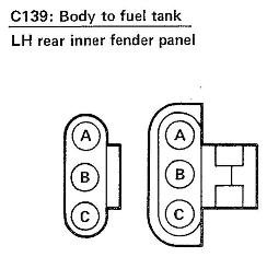
Vehicle wise: Gray w/trace: Left STOP/TURN. Blue: Running lamps. Black: Ground (case ground).
-
Purpose for testlight request, was it taxes the circuits better then a VM or ΩM would. Both VM & ΩM are high impedance instruments (low current flow). TL allows way more current to flow (ex: BL). I think all tested circuits are good and not part of the problem. Back to solve for X.
-
We still need to divide (X) out somehow.
-
Yes Disconnect If there're female terminal, yes one end of the TL (probe side) will work, but you may need something like a ice pick for the clip side. Be careful, you don't want them to touch.
-
You need jumper at FP relay for voltage supply to pump. TL connected between (A) and (C).
-
Connect TL between (A) & (C). Jumper wire at FP relay.
-
That leave us with testing at the fuel pump motor, disconnected, harness side. You'll need to use the FP relay jumper for this. Connect TL between C139_A and C139_C. TL polarity doesn't matter here, it just a bulb. With jumper in place, note reading.
-
Point taken.
-
While we're still under the hood it battery positive time. Connect TL clip to battery positive post. I'm using the 87 Electrical Manual. Probe the following: D1_3 D2_7 Touch firewall metal Touch engine block
-
OMG. To each there own, if guess.