89 MJ Posted January 3, 2022 Posted January 3, 2022 It certainly is! Not a lotta room for a lotta ponies, but it looks like it all is fitting so far!
JimBorecky Posted January 23, 2022 Author Posted January 23, 2022 Worked on a new air box that fits a evaporator a few months ago. Forgot to post. I took lots of pictures of it coming apart, but forgot to take photos of putting it back together. Used foam from a upholstery supply store.
JimBorecky Posted February 27, 2022 Author Posted February 27, 2022 So got the rims back from the powder coaters this week. I'm very happy..
19comanche86 Posted February 28, 2022 Posted February 28, 2022 So got the rims back from the powder coasters this week. I'm very happy..Wow those came out beautifully. I wanting to do the exact same thing. Sent from my iPhone using Tapatalk
JimBorecky Posted February 28, 2022 Author Posted February 28, 2022 Hint: If I were to do it over, I'd done a little more prep on them. Although they sand blasted them, it didn't take out any of the curb rash, and the coating isn't thick enough to cover it all. Some of it I feel I could have smoothed out a little better. Overall I'm very pleased. Hopefully the tire place won't mess them up. LOL. I chose a flat black. The coater said it should be pretty durable.
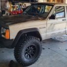
JimBorecky Posted March 11, 2022 Author Posted March 11, 2022 So the journey continues. I ended up buying a 3D printer since I noticed that most of the vendors are selling 3D printed parts. Plus I wanted to be a little creative with this truck. I created a new hub with the jeep logo to fit inside the wheels. ( I hit them with a filling black primer to get rid of the lines and take the shine away. Then bought spacers that had larger centers here. https://smile.amazon.com/dp/B01MRVH2NR?psc=1&ref=ppx_yo2_dt_b_product_details Designed and printed a cavity to go inside and hold the outside piece in place. The end result should be something like this. Here is the whole shooting match on the truck. 32x11.5R15's on a 4.5" lift. <- Rubs a little when turning VERY sharp. may invest in 1" spacers up front or adjust the stops. FYI - For those with 3D printers I used PLA and not ABS plastic so not sure how long they are going to last, but I can always reprint them. I included the STL files in this post in case someone wants to play. BTW I'm not a draftsman so you'll have to fix the model normals in the STL file. :) HubSpacer.stl JeepHub3.stl
JimBorecky Posted March 11, 2022 Author Posted March 11, 2022 Thought I'd add a little bit of the assembly here. Yes I put a little foam in between the hub pieces. The black tape is to hold the hub in place while I wrestled getting them mounted.
JimBorecky Posted March 13, 2022 Author Posted March 13, 2022 For those following. Swapping the 2 inch for one inch spacers helped a great deal. It stopped rubbing on the fender. but now rubs on the lower control arms, but you have to be turning hard.
JimBorecky Posted March 17, 2022 Author Posted March 17, 2022 On 3/12/2022 at 8:26 PM, Pete M said: what lower arms do you have? Got it aligned and they adjusted the stops. I'm good now. 👍
JimBorecky Posted September 16, 2022 Author Posted September 16, 2022 Thought I'd add a couple of additional pics. Engine bay is getting a little crowded.
JimBorecky Posted September 16, 2022 Author Posted September 16, 2022 Going to be my shift indicator.
JimBorecky Posted September 16, 2022 Author Posted September 16, 2022 3D printed a new transfer case shift indicator. File can be found here: https://www.thingiverse.com/thing:5378972
Pete M Posted September 23, 2022 Posted September 23, 2022 I don't see any of the pics. are you uploading them here to the CC?
JimBorecky Posted September 23, 2022 Author Posted September 23, 2022 So took the Comanche to it's first Car Show/Cruise In. I was shocked at the number of people wanting to talk about the truck.
Pete M Posted September 23, 2022 Posted September 23, 2022 I'm guessing I don't have access to your google account? I do see the images in that last post. most people have no idea what an MJ is, and those that do, probably haven't seen one with an engine swap. MJs are a curiosity for sure.
JimBorecky Posted September 23, 2022 Author Posted September 23, 2022 17 minutes ago, Pete M said: I'm guessing I don't have access to your google account? I do see the images in that last post. most people have no idea what an MJ is, and those that do, probably haven't seen one with an engine swap. MJs are a curiosity for sure. How about now?
Pete M Posted September 23, 2022 Posted September 23, 2022 I see the 3d printed pics! but still not the 2 posts above it.
JimBorecky Posted September 23, 2022 Author Posted September 23, 2022 2 minutes ago, Pete M said: I see the 3d printed pics! but still not the 2 posts above it. You should be able to see the other ones now. Thanks!
JimBorecky Posted September 28, 2022 Author Posted September 28, 2022 The adventure continues. I was told that if I ordered a 91/92 fuel assembly it would interface with my gauges and be the correct length. However they stopped making them years ago. I found a place that claimed it was for a 91 MJ. When it arrived it was for a XJ. SIGH. Instead of sending it back I decided to try and make it work, since it did make my gauge work in the correct direction. You can see how much longer the old assembly is in this photo, and of course everything is backwards. I figured I could use the old pump assembly and modify it. However I needed this bracket. I told my wife I've been watching too many Fab Rats videos. Cause out of frustration out came the cutting wheel. I figured with my luck, welding would blow a hole into the already hard to find fuel assembly. So I wasn't going to risk it. Time for good old fashion hose clamp method. LOL I was shocked how tight it all became. A little soldering of the new to the old. Bingo finished product. Some notes here. The old float was on the opposite side of the rheostat, compared to the new one. I tried to bend the old one up(As seen in the photo) hoping that would fly. It did not. I went back with the float the came with the new assembly. Which works better, but because it's not as long, takes longer to come off of full and shows empty long before it really is. I was in a hurry, and this was good enough for now. I'm going to try and heat/bend the old float so that it will work at a later date. Thanks for following this very SLOW build. :)
JimBorecky Posted October 17, 2022 Author Posted October 17, 2022 Ok so I've been having way too much fun with this 3D printer, and have gotten MUCH better at using FreeCAD. Decided to go crazy with the Designing parts. First goal fix broken Console. Printed a tab and then friction weld it in place. Of course I needed a light holder for the newly installed 4X4 indicator plate. I was thinking it would be easier and faster to design my own which I'll put in a separate post.
JimBorecky Posted October 17, 2022 Author Posted October 17, 2022 I decided to make a spare and document how the LED replacement was made. First the design in FreeCAD Some simple circuits. Print it out. :) Now the assembly. Note two things here. I used two resistors in the black one cause I didn't have a 560 ohm. I have a electrical engineering degree, so matching what I needed was child's play for me. :) I also created a second one with a lower resistance(grey) for brighter LED, but it will most likely burn out quickly. Insert the assembly and fill with hot glue. Install into the console. STL files for those with 3D printers. 4x4 shiftPanel LED holder-Body.stl 4x4 shiftPanel LED holder-M12-Nut.stl
JimBorecky Posted October 17, 2022 Author Posted October 17, 2022 So the boot for the shifter is functional. But since I'm playing already, I thought what the heck. I'll post additional pictures and how too, when it's working in the truck. So I printed this with a thin layer so you don't see the indicator when the truck isn't running. Used temporary power to see how it looked.

Recommended Posts
Create an account or sign in to comment
You need to be a member in order to leave a comment
Create an account
Sign up for a new account in our community. It's easy!
Register a new accountSign in
Already have an account? Sign in here.
Sign In Now