
howeitsdone
-
Posts
691 -
Joined
-
Last visited
Content Type
Profiles
Forums
Gallery
Everything posted by howeitsdone
-
Flywheel Condition Opinion
howeitsdone replied to howeitsdone's topic in MJ Tech: Modification and Repairs
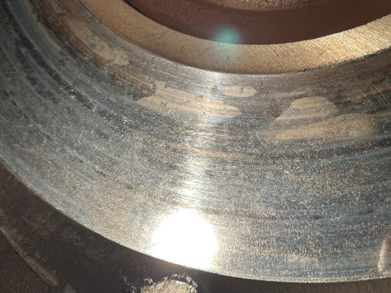
Might just do that then. I was more concerned with the coloration since the surface is very smooth. -
Flywheel Condition Opinion
howeitsdone replied to howeitsdone's topic in MJ Tech: Modification and Repairs
Not quite sure how to gauge the flywheel performance. The clutch was at the end and I know that feeling which was what it seemed like. Smelled bad and the occasional slip (thud) when too much torque applied stationary. I know those are also bad symptoms of a flywheel, but if the clutch has no material then the same happens. Hard to tell. -
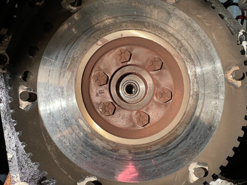
Wanting a second set of eyes on this flywheel. Sort of looks like heat spots but then again the blotches aren't 'blue'. Very smooth surface. I didn't find a surface variation threshold in the manual to even warrant checking that.
-
Nice work. Just noticed you only said the cluster doesn't illuminate. Does the blinker itself work?
-
If you're interested in learning the RMS repair yourself it's pretty simple. The hardest part is scraping off an original or cork gasket. Didn't you say the seal was replaced recently? If so, it may not be so bad of a job. It's just a little messy. We don't have a girdle which helps speed things up a bit.
-
I swapped mine over so I didn't have to deal with it.
-
Internal code is C102, but that won't get you very far unfortunately. Would be best to pull one from a JY/Classifieds or just purchase a weatherproof 10-pin connector and install in-place. At least that way you start corrosion free.
-
https://www.facebook.com/groups/219461385213710/permalink/1355817371578100/?sale_post_id=1355817371578100 They're actually in S. Wisconsin, not IA
-
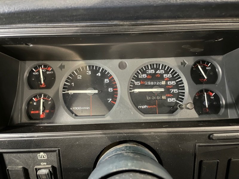
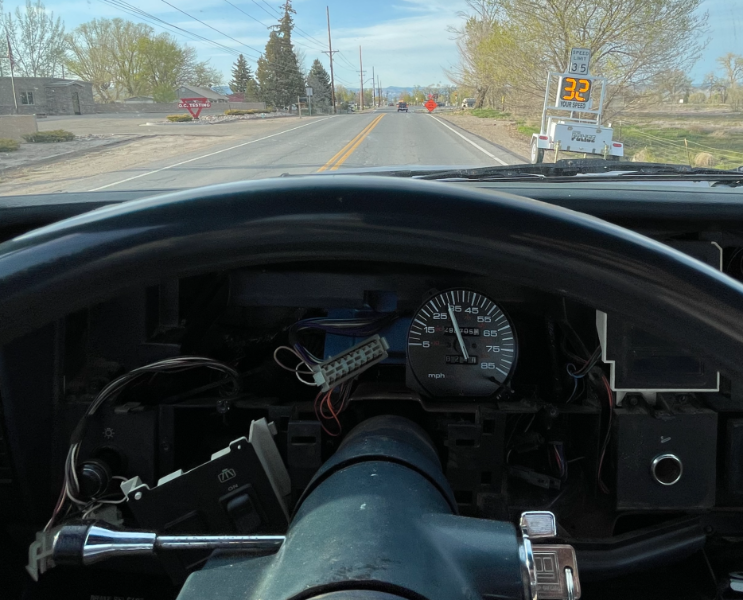
Scored a full cluster from the local ads for a very good price. Since it’s my first time working with a cluster there were some errors. Battery voltage isn’t reading because the needle won’t attach. And then I opted to swap the odometer right over and not mess with setting the mileage. I didn’t realize the needles were calibrated though and it said I went 85mph! I guess these add extra HP! Luckily there is a speed trap set up down the road so I was able to calibrate it just fine. Looks a million times better! Eventually I’ll fix the voltage…
-
Bruce has to enroll at MJ academy
howeitsdone replied to brucecooner's topic in Member Projects: Your Comanches
Bring on the questions! I learned a lot here. Also... -
Rear: Jack under pumpkin and stands under shafts is fine. If you have to work on the axle or leafs then the frame is where you'll need the support. I don't recommend putting stands under the leaf springs (because jack stands are curved and you'll get better contact on the axle shaft). You can lift from there if needed though. Front: Jack under the pumpkin raises the driver side more. You can lift from there and place a stand under the shaft or lower control arm for support and then lift from the passenger shaft and place a stand under that shaft or LCA also. Again, the frame right behind the control arm mount is factory recommended, and required if you have to do work like replacing the axle, etc.... A 6 ton stand is ideal for frame support (because of height, not weight), but 3 ton will work fine if supporting from the axle. You can still jack up from the axles and get it high enough for the 6-ton stands to support the frame. If you need additional height from your jack, then you can use wood like 2x4s or 4x4s, but typically don't need to unless you're lifted a lot. The axles are tough and you won't do damage to them by lifting from there. I'm sure there are ways to damage them if you tried really hard, but I've had no problems. Goes without saying, but always make sure to chock the wheels and have the transmission in gear.
-
Control Arm Calculations (Actual Geometry)
howeitsdone replied to howeitsdone's topic in MJ Tech: Modification and Repairs
I can see that in my manual. But that's not what this post is about. I know how to adjust the arms and get my angles, but that's not the point of this post. The math should work with anyone's actual measurements; not just factory. I'm interested in the math. Maybe not the forum to ask such a question. No problem
-
Seafoam in the oil- Any risks?
howeitsdone replied to Eriko5000's topic in MJ Tech: Modification and Repairs
Like mentioned, you'll be fine. Just make sure to change the oil within about 25 miles so you get the gunk out and it doesn't sit in there. You can also take and add it to the brake booster vacuum line (unhook booster side) to clean the pistons and ignition system. That one can be tricky, but highly effective. Two other great brands for a pre-oil change clean are AMSoil & Liquid Moly. Both have an Engine Flush product that also work great. -
Control Arm Calculations (Actual Geometry)
howeitsdone replied to howeitsdone's topic in MJ Tech: Modification and Repairs
Thanks guys. If you read my first post you'll see both your comments addressed. Was hoping there was someone here with the math knowledge to help me understand. I want to learn the math itself as I understand most of it pretty well. Another skill I'd like to add to the pile. -
Missing an oil pan bolt
howeitsdone replied to brucecooner's topic in MJ Tech: Modification and Repairs
lol they split though. So typically you'll find one in the low end that can't go high and vise-versa. I have a 15-80ft/lb wrench from Amazon and then a 25-250ft/lb ACDelco adapter with the fancy buttons and shrieking sounds. Unless you want to spend big $$$ to have best of both you'll need a couple for the range needed. I torqued mine to 15ft/lb since that's the lowest I could. Worked just fine. Good luck though! Make sure to post your build in the forums so we can follow. -
Missing an oil pan bolt
howeitsdone replied to brucecooner's topic in MJ Tech: Modification and Repairs
No problem. As far as torque and loctite, IIRC it's 13ft/lbs and really no need for loctite, but blue if you want to go that route. My brother (a service tech) laughed at me when I told him I torqued the pan bolts. But it's added peace of mind for someone who doesn't do it for a living! -
Missing an oil pan bolt
howeitsdone replied to brucecooner's topic in MJ Tech: Modification and Repairs
Not dangerous, but you want the most surface area contact as possible to prevent leaks. Here is a photo showing the bolts. Looks like one of the front bolts based on the pulley in your photo which is 1/4". ACE Hardware is a great place to find one if it's in your area.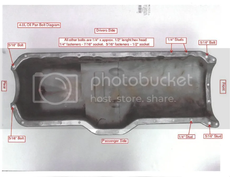
-
Control Arm Calculations (Actual Geometry)
howeitsdone replied to howeitsdone's topic in MJ Tech: Modification and Repairs
I played around with versions 3 & 4 and while it helps visualize, I can't seem to figure out how to get the output link length in travel(2) correct. What is the 'x' Frame End measurement? Shouldn't it be the current link length? I assumed the Axle End was the offset to the front axle centerline and it visualizes correctly. If I put the Frame End as my current arm length it also visualizes correctly, but the output of what the link lengths should be are very wacky. Given that the horizontal separation never changes (on stock-style setup) I can't see where that number would have an effect. I could be completely wrong, but it's a constant no matter what. For reference though, I have the actual measurements below that I took from my truck: UCA @ Frame - 23.50" UCA @ Axle - 24.50" LCA @ Frame - 30.50" LCA @ Axle - 33.00" Someone solved the formula for the LCA calculation regarding the chart floating around: a = Amount of Lift + 0.30427 b = 15.7471 (stock length) Length Needed = √(a² + b²) However, I doubt engineers came up with this to calculate it themselves. I'm sure the actual geometry of the suspension is in the equation. '0.30427' means nothing lol It's just a correction to get the equation to work essentially.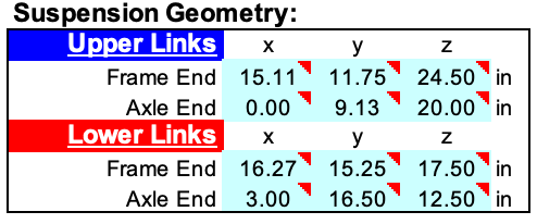
-
Control Arm Calculations (Actual Geometry)
howeitsdone replied to howeitsdone's topic in MJ Tech: Modification and Repairs
Would these be the only variables needed to begin with? I would imagine there would be another variable of adjustment needed for the LCA. Which based on my above assumption, would just be the distance to put back to target WB length. Then, effectively we would solve for 'a' and be done?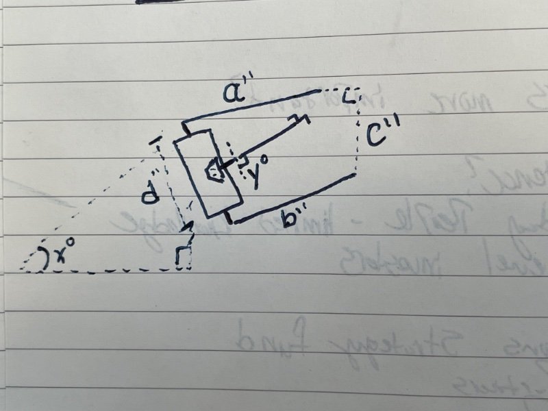
-
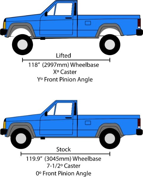
Wondering if there is a math wiz on here. Firstly, not interested in being pointed to a chart or told "Just do this...". I've read all those forums and posts. I actually want to learn the math. If anyone knows a resource to use that would be nice too. I know there are some smart people in here. My other option is redrawing the parts 1:1 scale digitally and just playing around, but I don't really learn the core equation(s). Clearly control arm length directly correlates to caster and pinion angle since only those can rotate the axle. I have a generic mockup of the whole premise below. The lifted wheelbase is just arbitrary since we are not given the amount of lift. Although, it can be calculated but that's not the point. It's my understanding the LCAs set the axle position along the X-axis relative to the image. Adding shims or using adjustable control arms would put you back to the target from factory when needed. This applies whether lifted or stock, correct? Meaning that no matter what, 119.9" will always be the target? I'm not talking about what people get by with or runs well. I'm talking about actual targets and baselines. The example image needs to be corrected back to the stock geometry when lifted. Based on the new wheelbase, how would you go about determining the length adjustments for both UCAs and LCAs needed to get back to those original numbers without trial and error methods? I would think starting from stock lengths (15" & 15-3/4") would be a given as well as the Y-axis distance between the UCA and LCA mounting points both axle and frame. Then it becomes fuzzy...
-
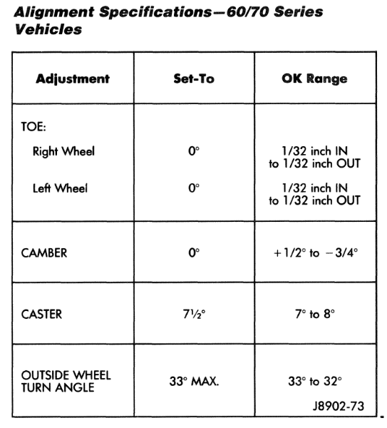
I removed the LCA shims and my caster is now 9.5º; It was like 11-12º. The pinion angle is about 7º. Thinking the arms just need a turn or two.. Got the UCAs unbolted from the axle yesterday and will adjust today. When I removed the LCA shims, I did a toe alignment and ran it down the road at 65mph and it did feel better. Almost like it would cruise better. But I still have this awful right pull. I thought it might be a bent axle, but I had the same problem with the original D30.
-
So I was having a weird clunk noise in the front this weekend when giving throttle on a hill. 99% positive that the reason is because of the awful 10.6º pinion angle in the front. For some reason it never crossed my mind to check it, but I just had the random thought in my mind to check it. I'm going to remove all the shims in the LCAs and start from there. The UCAs are measured identical to the lift chart suggestion, but I'll adjust if needed.
-
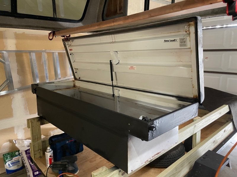
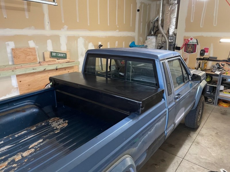
I also picked up this toolbox for $40. Sanded, painted, and put some rubber on the bed so it won’t scratch. Wish I did this sooner!
-
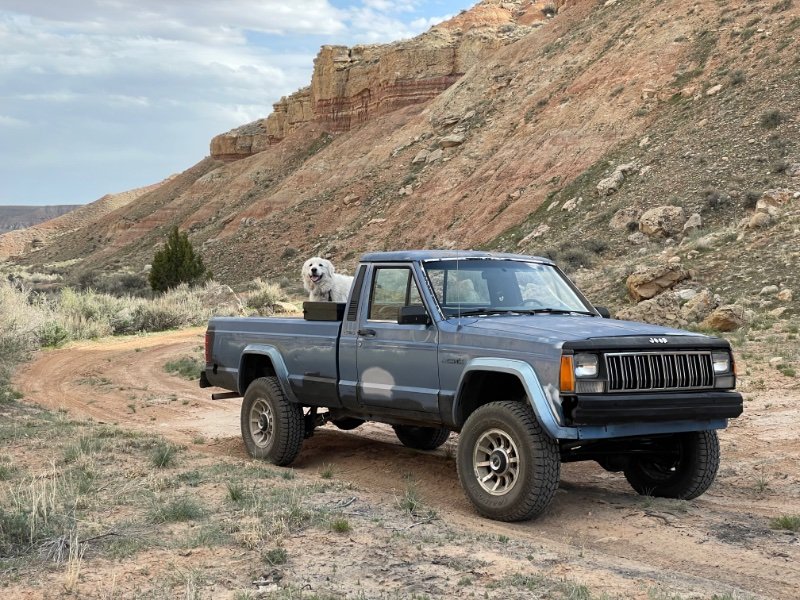
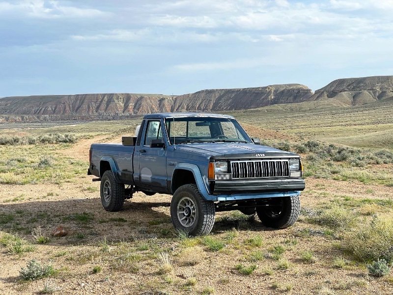
Finally put some dirt under the tires this weekend! The rear main took another loss on me. Still got me where I needed to go through steep hills and lots of sand though. Not disappointed at all with the 3.55 gears. They don’t like 7% grades on pavement, but off-road they did just fine.
-
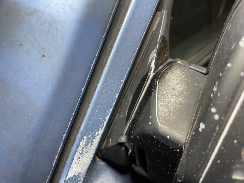
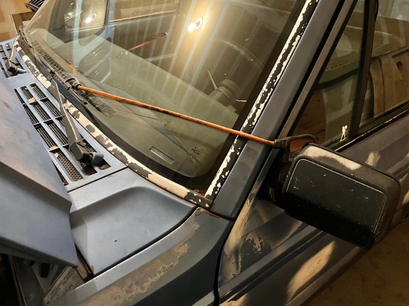
Forgot to mention as well. My driver mirror was stuck in limp mode I applied clear RTV/Adhesive and held it in place overnight. Worked great! I could've applied it a little neater, but we're here...