agamble
-
Posts
214 -
Joined
-
Last visited
Content Type
Profiles
Forums
Gallery
Everything posted by agamble
-
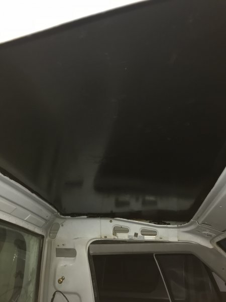
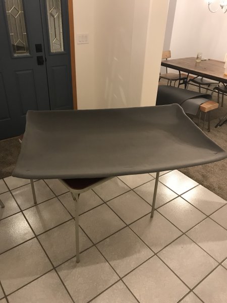
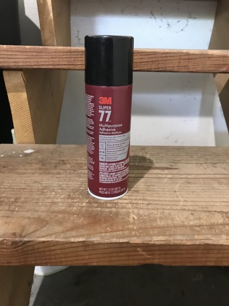
The original plan was to put a piece of sound deadener and heat barrier mat on the ceiling of the cab. To my surprise on removing the headliner I found a large amount of rust on the cab ceiling. I knew the windshield leaked, the only thing I can think of is that when it leaks some of the water that enters becomes trapped between the roof and some foam sleeping pad matting that had been installed at some point in time between the headliner and the roof. So my afternoon entailed applying Chassis Saver to the roof to stop the rust. Since the headliner was going to be out of the cab for more time that originally anticipated I made a jaunt to the local Joann's fabric store for headliner replaced material and recovered the headliner. 3M Super 77 was also used to glue the headliner down. Heavy coats were sprayed onto the back of the material and onto the headliner. Once the glue was given a few minutes to become tacky to the touch the material was smoothed out over the headliner.
-
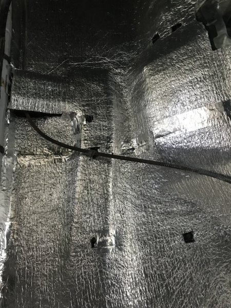
With easier interior items completed I moved onto more time consuming things. To reduce the amount of noise and heat inside of the cab the factory placed a foam backing on transmission tunnel cover. 28 years later it was dry and deteriorated. When I removed the dry foam a sticky residue was left over from the adhesive that was used. Olive oil is a cheap and effective way to remove sticky things. A few ounces of olive oil, ample time and some elbow grease removed the sticky residue. With sticky stuff gone I put down a sound deadener & heat barrier mat. Don't recall the exact brand, but a 4' x 10' roll was purchased off of Amazon. The mat doesn't have an adhesive backing. 3M Super 77 was used to stick it down. Seams between matting were taped using foil tape. Shots of the finished product.


-
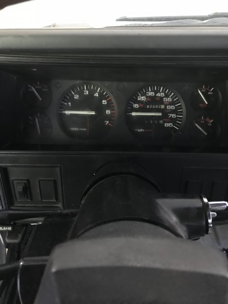
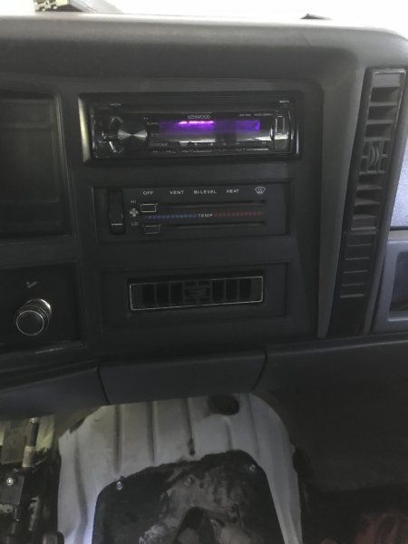
With the door wiring out of the way attention was moved to other interior items, such as swapping in a full gauge cluster to replace the dummy lights and installing a newer head unit. While reinstalling the fenders the front fangs were trimmed.
-
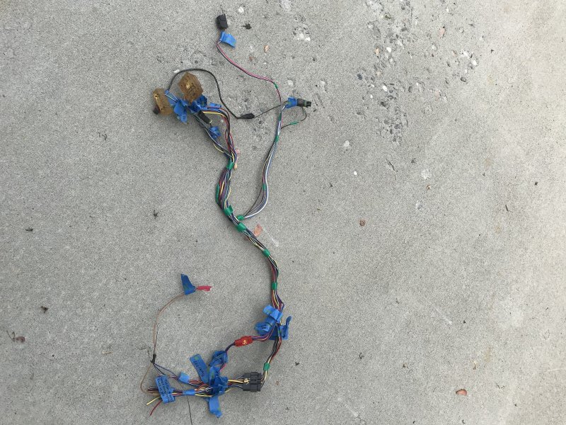
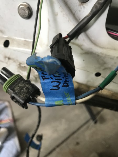
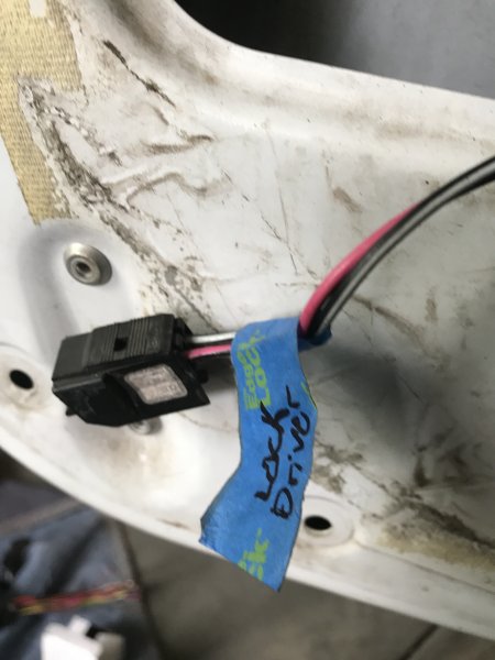
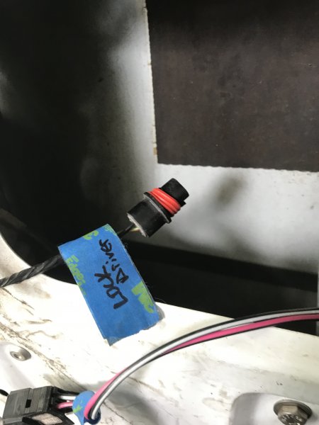
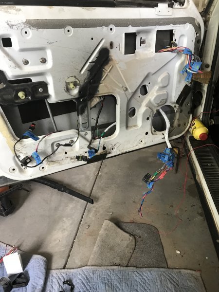
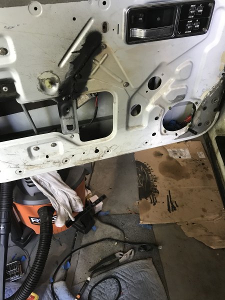
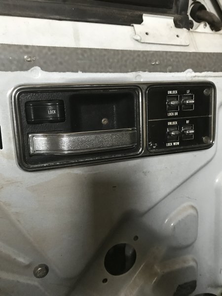
I next decided to tackle the wiring for the power windows and locks. The truck originally had manual windows, but the original doors had the towing mirrors that over time rusted out in the mounting points and left large holes in the door. The replacement doors that came from an XJ came equipped with power windows and locks. When the windows were first wired the the drivers side control panel only operated the drivers door window and lock. I wanted to be able to open the passenger side window without having to lay across the truck to open and/or close the passenger window or lock the door.Earlier in the year a trip to the junkyard netted a wiring harness from 4-door Cherokee with power windows and locks. I stripped the wiring harnesses from the doors and into the cab and grabbed the master control panel. As I'd never done this and I couldn't find a wiring diagram online I started by unraveling the wiring harnesses and tracing each wire to see where and what it went to. Then using some painters tape labeled them for reference. Once I knew what went to where I rewrapped the wire harness. With the help of HOrnbrod I drew up the wiring diagram that I needed for my application. While perusing Ebay I came across a master control switch for a 86-96 two door Cherokee for cheap. While the wiring harness is for a four door, I adapted it to work with the two door control switch. While perusing Ebay I came across a master control switch for a 86-96 two door Cherokee for a reasonable price making for a cleaner look. The wiring harness was then adapted to work with the two door control switch. After mapping out what goes to where the wiring harness was installed. To connect the master control switch to the passenger door the harness was tucked up and run under the dash. The locks and windows worked.......for about a day. The passenger window regulator died on me while I was testing it out. It goes down with no problems. Going back up I have to flick the switch on both the master control switch and passenger switch multiple times to get it to go back up. So a new regulator is on the to do list.


-
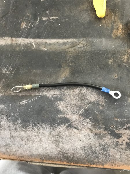
Completed Cruiser54's tip #18 - Improving the Instrument Panel Ground. In his recommendations the cable is recommended to be 12" long. I only went with about 6" and attached it behind the support for the steering wheel.

-
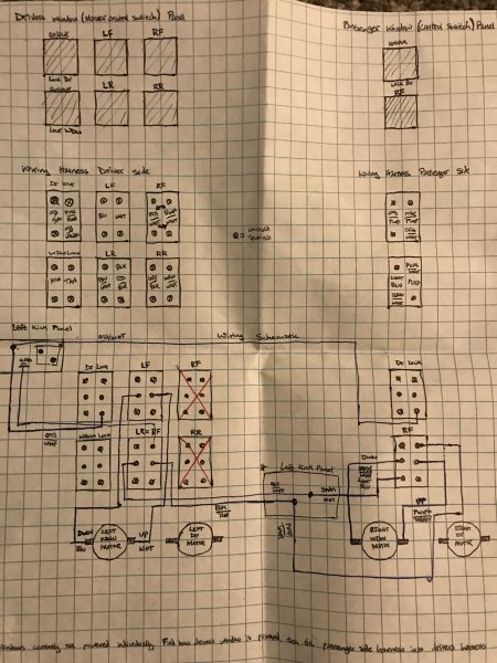
Guessing. I was being lazy and didn't want to take the time to find or draw. I have since seen the error in my ways and took the time to draw out a wiring diagram and found the solution to the problem. Below is the diagram I drew for reference: The problem was I was putting power to the negative side of the switch, which in turn was causing the fuse to short out. The solution was I need to add a fourth wire. One for power, one for ground, one to connect the positive of the passenger side motor, and a separate for the negative side of the motor.
-
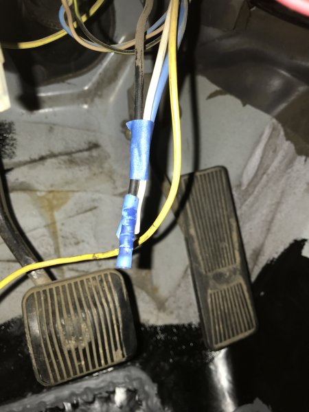
I am attempting to wire up power windows in the Comanche. Nothing is hardwired yet, as I am trouble shooting. I've tapped into the fuse box, crudely for now, which runs through a fuse. It then splits into two. I have one line powering the master control switch on the driver side, the other goes to the passenger side control switch. As it stands I can get the master control switch on the drivers side to open and close the drivers side window. Then I am able to get the passenger side control switch to window to open and close the passenger window. The problem is when I try connected the master control switch for the passenger window in. To tie them, the master control switch and the power window motor, together I have taken a third wire, which I tied into the master control switch passenger window wires, then ran that over to the passenger motor wires. When I attempt to tie the master control switch in to be able to also control the passenger window I keep blowing the fuse. If it doesn't blow immediately upon connecting the wires, as soon as I flick the master control switch for the passenger window it will blow the fuse. What am I doing in correctly?
-
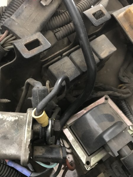
When I first when to test the push rod length on the brake booster I had to connect up the battery to get power. When I put the negative cable onto the post the truck starts turning over. Thinking I left the ignition in the on position I go to turn it off and see there are no keys and the ignition is turned off. Odd right, maybe it was a fluke. I go and connect the negative cable again and the truck starts turning over again. As long as the cable is touching the post the truck will crank. Now I am thinking I have a problem and I've never personally had this problem nor heard of this occurring. Off to the inter web for possible solutions. First solution: I have the starter wired up incorrectly and/or the cable terminals is touching something it shouldn't on the starter. Out to the garage and loosen the starter wires, reposition, and ensure that nothing is touching. Crawl out from under the truck, put the negative cable onto the post, the truck starts turning over. Go back into the house and read some more. Second solution: Could be a bad starter solenoid. Out to the garage and under the truck again. Now I remove the whole starter to test the solenoid. Test the current one it checks out. Crawl back under the truck and put the starter on and connect it back up. Put the negative cable to the post. Truck starts cranking. Several threads read that even if the starter solenoid tests out it could still be bad. So I crawl back under to remove the starter....again and swap the starter solenoid for a good one that I randomly have on hand. Crawl back under and connect everything back up. Get out from under the truck, touch the negative battery cable to the post, truck starts turning over again. Back into the house to read some more possible reasons. Third and fourth solutions: Several threads talk about a bad starter relay or a faulty ignition switch. At this point I start thinking I know that they can't be bad as the truck was running flawlessly a month ago before I started swapping parts over. I try to remember the K.I.S.S concept and realize these are getting more and more complex in repair and diagnostics. So I begin to think what have I done that might lead to this. The only thing that I have done with the electrical system was swap the battery cables. So I go out and start tracing the cables and everything looks to be connected correctly. Doesn't make sense.....I trace again, more carefully again and then I notice this, almost hard to notice but somehow I did. The positive battery cable that connects to the starter relay is just, and I mean just touching the plastic on the connection for the starter solenoid. I loosened the nut on the starter relay, moved the cable terminal away from the connection, tighten everything back up. Go to touch the negative cable to the post, no cranking. Two hours and some change later, problem solved.
-
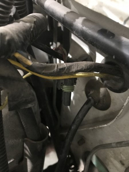
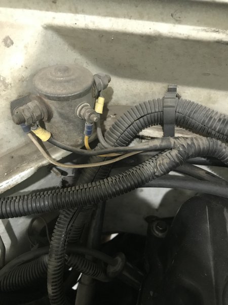
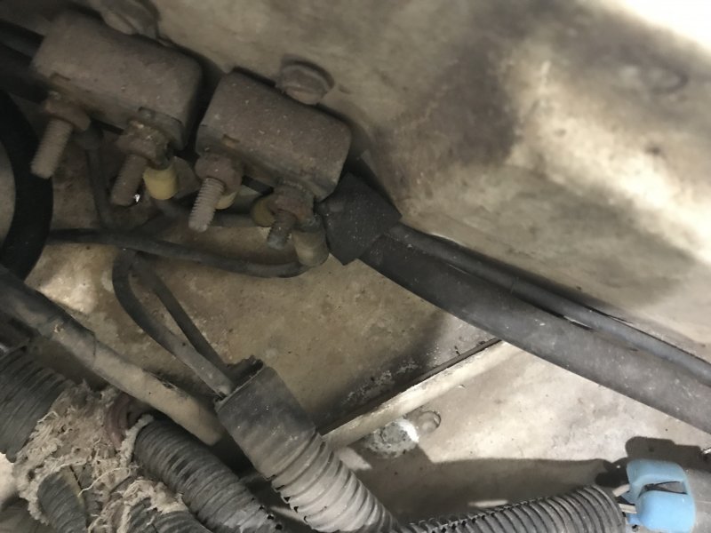
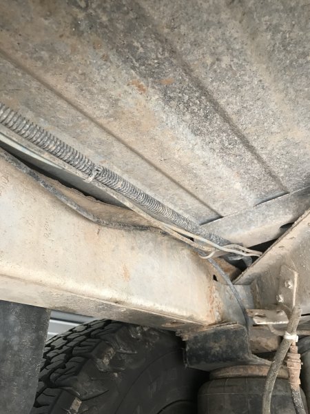
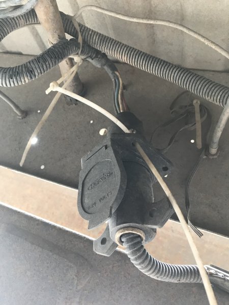
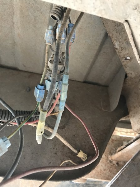
I like everyone else like closure to problems that have been encountered. I don't know how many times I read tech problems where the original poster never reports back on if and how the solved their problem. In an attempt to not follow suite I believe that the mystery components have finally been solved. I finally tracked all the wires. As was stated previously by two other members they appear to be parts of a trailer braking system. I found a bundle of wires tucked up under the dash that did not connect to anything. Following them,they went through the firewall into the engine bay and connected to an extra wireloom which ran in two directions. Along the back of the firewall towards the passenger side and down the back of the firewall towards the transmission tunnel. The portion that ran to passenger side split, connecting to the solenoid. Then continued to the two thermal fuses on the inner passenger fender. Which then connected to the starter relay. The portion going down to the transmission tunnel ran along the inner frame rail. Until it met up with this rats nest of electrical connections. Which all tied into this trailer connection.
-
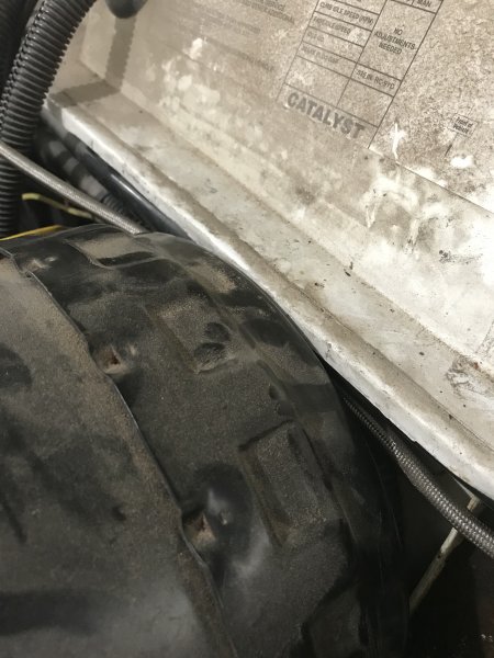
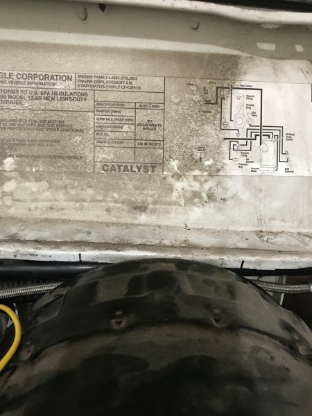
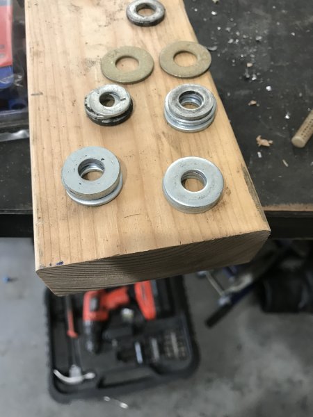
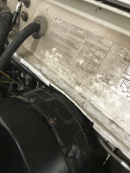
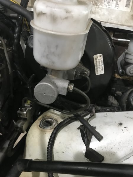
84’-94’, Comanches and Cherokees came with a single-diaphragm brake booster. While this worked OK for stock once larger tires and a lift are added the lack of braking quickly becomes apparent. The later Cherokees and Grand Cherokees use a dual-diaphragm booster, which increase pressure in the brake lines, applying more pressure to the brakes, resulting in faster stops. There are multiple ways to do this swap and I'm not going to go into great detail as there are sufficient write ups to be found. I used 00’ WJ booster and master cylinder, it’s rumored to give a bit better braking. Below is a side-by-side comparison of the stock Comanche booster vs. the Grand Cherokee. The push rod on the Grand Cherokee has to be modified to allow for the brake switch to be installed correctly. Getting the push rod to the right length was the most time consuming portion. Initially, I ground too much off, and the brake switch wouldn't activate the brake lights. JB Weld was applied to the end of the push rod, then sanded that down until it was the correct length. For the larger booster to fit the firewall needs some modification. I marked the section that needed to be moved to allow the booster to be fully seated. Then I used a dremel to make relief cuts, then using pliers folded the lip up and under. The lip still needs to be raised up slightly to allow the booster to fully seat into position. It’s recommended to use a ¼” spacer to keep the push rod lengths similar. After measuring the distances between the 89’ and the 00’ boosters, and seeing the significant height distance in the brake pedal and accelerator I decided to use a spacer. If you grabbed the booster from the junkyard often times you may find a factory plastic spacer, I didn't have one, but I did have a number of unused washers. A couple test fits and I had the correct amount of washers. For my application it ended up being each stack was 6.7mm in height. The Grand Cherokee brake master cylinder uses uses bubble flares at the connection, so new 3/16 brake lines with bubble flares at the master cylinder and double flares at the proportioning valve are needed.

-
Thanks. They can still be found for a reasonable price with a bit of searching and patience. But like the comanche going the way of the dodo.
-
Done and done.
-

Hooligan OffRoad Hinge Support Install
agamble posted a topic in MJ Tech: DIY Projects and Write-Ups
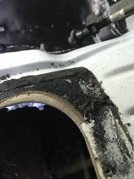
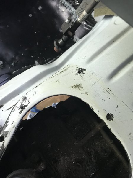
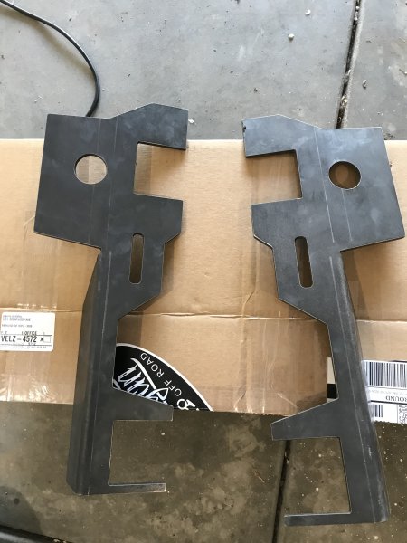
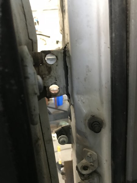
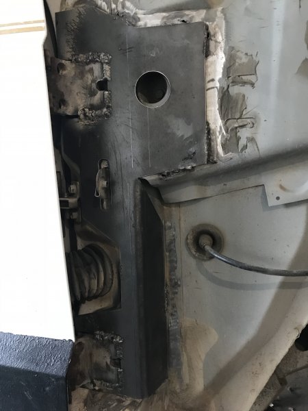
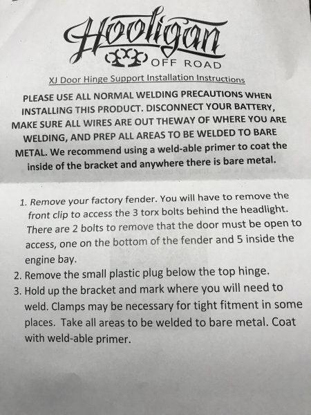
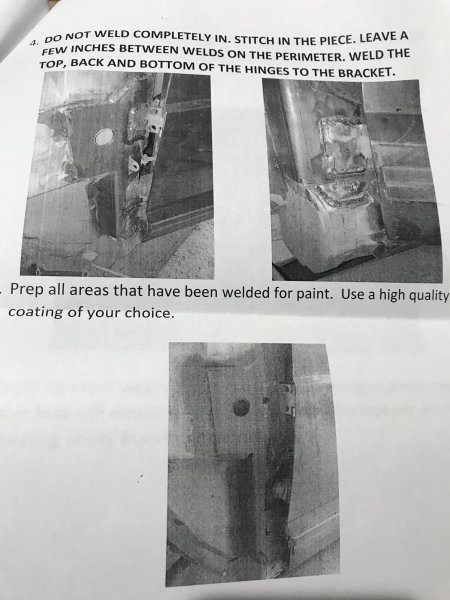
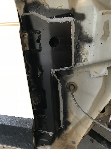
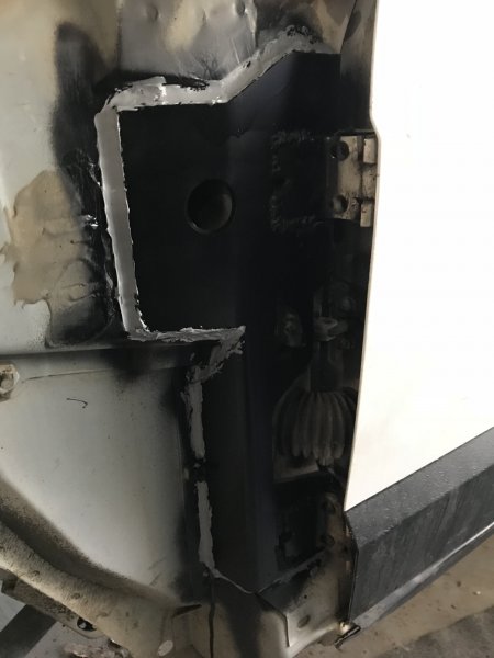
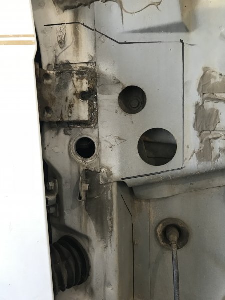
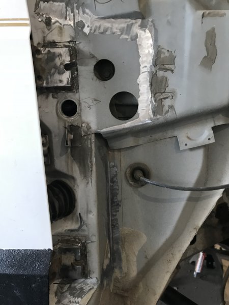
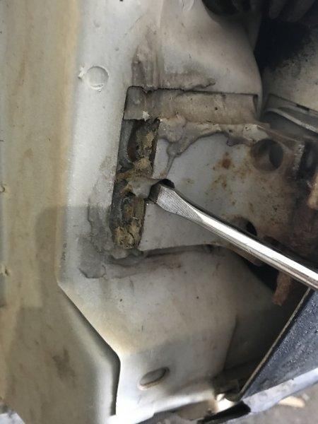
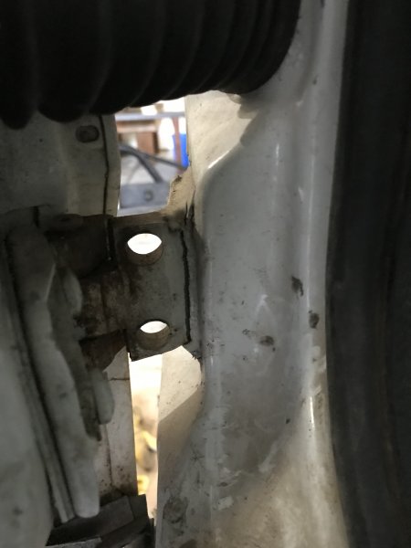
A common problem with the XJ and MJ is that the factory door hinge welds tend to break free from their mount. The drivers side door on my MJ was suffering from this problem on both the upper and lower hinges. To get the door to unlatch you had slightly lift the door up to get the door up over the stricker. While surfing the web for a solution, I came across this product from hooliganoffroad: https://www.hooliganoffroad.com/collections/xj/products/xj-door-hinge-support A quick read of the product description and I had placed an order. The box came complete with instructions and couple decal stickers that are guaranteed to increase horsepower output and offroad prowess when adhered to your jeep. The instructions are brief, literally 4 steps, but clear enough. Installation requires removing the front fenders to gain access to the door hinges. I didn't take any pics of removing the fenders as this has been covered in several other threads on multiple forums. With the fenders removed I started by cleaning off the foam sealant that the factory had placed over the welds. I flat head screw driver made quick work of it. It took about 5 minutes to get both door hinges cleared. After the removing the foam sealant I did as the instructions require. The plastic plug that is located under the upper hinge on both sides needs to be removed. The same handy flat head used to remove the foam sealant was able to make quick work on the plastic plug. With the plug removed, place the bracket onto the body and trace the perimeter to see where the metal needs to be cleaned. The brackets only go on in one direction. With the perimeter traced, with a sanding disc, I removed all the paint and primer to reveal bare metal. Make sure to get the outer perimeter and the hinges. To keep the bracket in place, I used a mini C-clamp in the hole that is visible in body and bracket. Once secured, stitch weld the the outer perimeter of the bracket, making sure to leave a few inches in-between each weld. Then weld the entire mating surface of the hinge to the bracket. While welding I did the top of both hinges on the passenger side, then while allowing the metal to somewhat cool, I moved to the drivers side and repeated the same process. Then moved down the sides, and the bottoms of the hinges. After things were cooled I applied two coats of Rust-O-leum paint and primer onto the bare/exposed metal to prevent rust from forming. And as a final step, I used seam sealer on the outer edge to seal out where water is likely run between the bracket and body. Once done a couple tests of opening and closing the door found that it was no longer sagging when open and they feel much more solid than before on the truck.


-
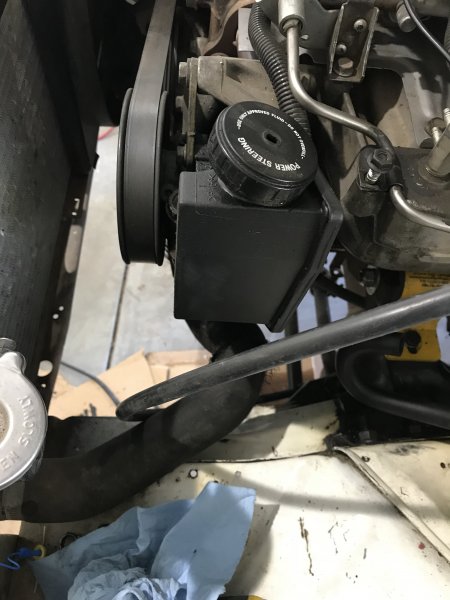
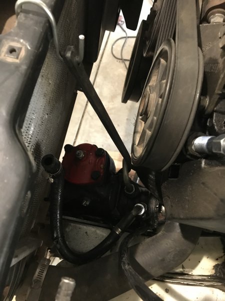
Finished with the door support brackets from Hooligan Offroad. Applied two coats of Rust-O-leum paint and primer to cover up the bare/exposed metal and then as overkill put some seam sealer on the outer edges to keep any water from getting in between the bracket and the body. I also swapped over a remanufactured RedHead steering box. Their process for remanufacturing the steering box includes: Machining out the housing and installing needle bearings Replacing the shafts and installing new control valves Custom fitting each worm and piston assembly with over-sized ball bearings While installing a heavy duty telescoping steel steering shaft made by Borgeson. To make installation easier I removed the brake booster and brake lines. While attempting to remove the power steering lines I broke the plastic nipple for the return line off. So until I order a replacement, the lines will have to hang there.

-
As I recall, the mounting holes do not line up directly. If you were to use the later model clutch master cylinder you would need to drill out a new hole in the fire wall to get it to bolt up correctly.
-
It won't be exactly like the first go around, but when I get to that stage as I swap everything from my SWB to my LWB I can do a better job of documenting the process and getting some pictures.
-
The Comanche was also suffering from another common issue with both the MJ and XJ. The driver's side door had broken free from the factory welds. To get the door to unlatch you had slightly lift the door up to get the door up over the striker. While surfing the web I came across these products from hooliganoffroad: https://www.hooliganoffroad.com/collections/xj/products/xj-door-hinge-support. I placed an order for them about the same time I ordered new floor pans. I figured I could do all the necessary welding at once. The shipping box came complete with instructions and couple decal stickers that come with a guarantee to increase horsepower output and offroad prowess when adhered to your jeep. The instructions are brief, literally 4 steps, but clearly instructs installation. Installation requires removing the front fenders to gain access to the door hinges. I didn't take any pics of removing the fenders as this has been covered in several other threads. Once access to the hinges is gained, the instructions call for removing the plastic plug that is located under the top hinge of the door. Place the bracket up to the body and trace around the outer edge and clean to bare metal. The door hinges had a foam placed over the top of the factory welds. The foam was readily removed with a flat head screw driver. It took about 5 minutes per side to clean off all the foam. After cleaning to bare metal, clamp the bracket into place to get a snug fit. I used a mini C-clamp placed into the opening that is visible in the picture below to secure the bracket to the body. When welding the bracket onto the body you only need to put couple stitch welds along the outer perimeter of the bracket. Then completely weld the door hinge to the bracket.


-
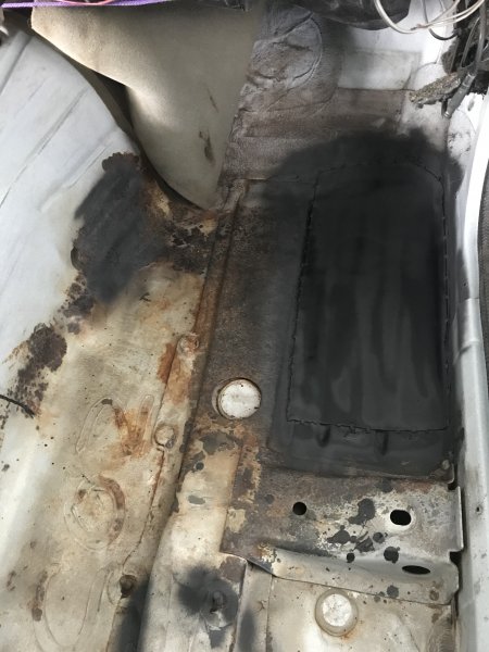
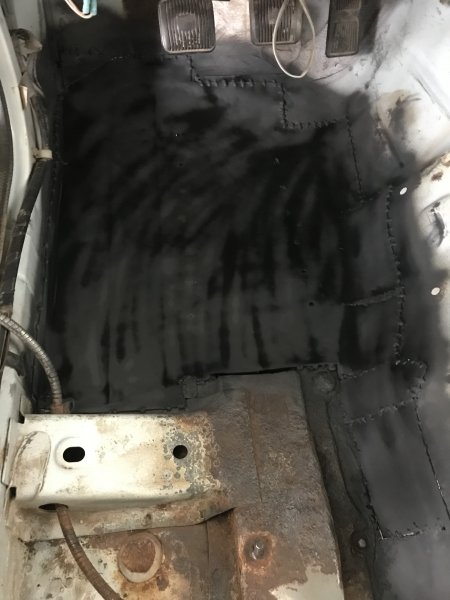
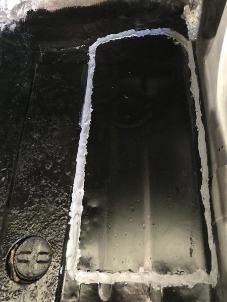
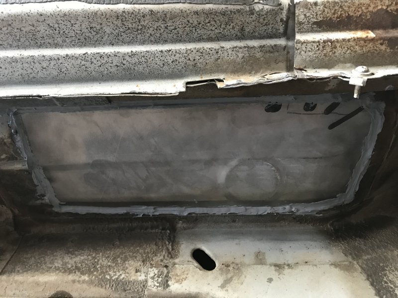
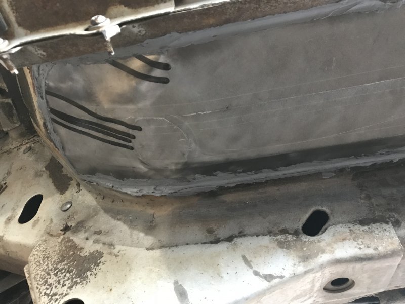
I didn't do any welding on the underside of the floor pans. They were installed like they were from the factory, I drilled multiple plug welds to weld it directly to the U-channel of the unibody. I tried to not have too much over lapping steel, most of the floor pans were situated to mate up. The biggest issue I had was when I tried to stitch weld it all together I would repeatedly burn through. I ended up applying multiple tacks around the circumference of the patch like I saw on a couple youtube videos. Once it was all tacked in a bead of seam sealer was applied over the the weld joints both inside and outside. On the outside the seam sealer is going to be covered with Chassis Saver.

-
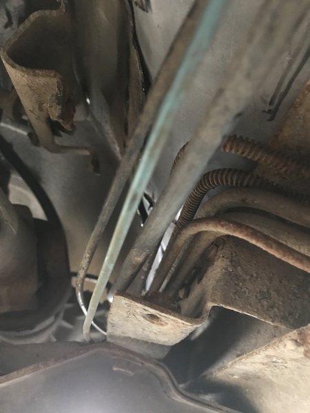
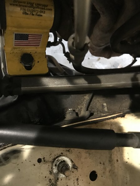
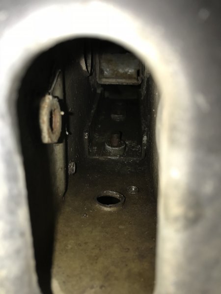
I am seeing if anyone has had this dilemma and if so how they were able to correct it. I have a sway bar bolt that won't come out. As you can see in the picture the portion the bolt threads into broke free of its welds and spins while attempting to loosen the bolt. I can't get anything in there with enough force to pinch it and loosen it out. Its smooth so I cannot put a wrench on it. The only solution that I can think of, and I don't want to do it, is cutting a section out of the box frame to try and tack it again.
-
The bolt pattern on the fire wall is different. You would need to drill our a new hole to allow it to mount correctly. I misquoted earlier. The advanced adapters hydraulic fittings allow you to use the correct mounting clutch master cylinder.
-
I did a similar swap awhile back. Here is some of the take aways from my experience. External Slave, 98’ Jeep Cherokee Install -Due to the differences between the Renix era and newer OBDI/OBDII computer systems, when installing the clutch system the Renix era fly wheel and CPS sensor must be used with the newer transmission. -When Chrysler changed from the internal slave setup to the external slave, the transmission input shaft diameter was changed meaning if you are using an external slave AX-15 in an older 4.0L a new pilot bearing may be in order. BA10/5 and internal slave AX-15s have a pilot bearing with an ID of 0.5934 inches, OD of 1.055 inches, and depth of 0.719 inches (OE part number 53009181). External slave AX-15s have a pilot bearing with an ID of 0.7518 inches, OD of 1.8161 inches, and depth of 0.719 inches (OE part number 33004041). -I read on multiple conversion threads that 73’ CJ, 350 V8 pilot bearing is recommended when using an external AX-15 in an older 4.0L. It has an ID of 0.751 inches, OD of 1.056 inches, and depth of 0.88 inches (National part number PB77HD or Dorman part number 14674). But in my personal case I found the 73’ CJ pilot had too large an OD to fit into the back of the engine, I found that the external AX-15 pilot bearing that came with the 98 Clutch kit fit into the space, so I am running that one. -As mentioned you will need a matching 23 spline transferase. The transferase input shaft bearing comes in three sizes, short, medium(rare), and long. For the XJ AX15 you'll want the short shaft length don't have part numbers. -The slave cylinder you have listed will not work without modification, as the master cylinder will need to have the firewall modified to mount it. You can use an internal slave cylinder for the MJ and Advanced Adapters sells hydraulic fittings (716130 : Master Cylinder Fitting for Jeep YJ Wrangler and 716130F and Slave Cylinder Fitting (-3 style x 7/16" inverted flare)) and a stainless steel braided clutch line (716130H : Stainless Hose 42" Length), or the whole kit (P/N#716340) to connect the internal slave clutch master cylinder to an external slave cylinder. -The throwout bearing and shift fork. - And finally you will need to rewire you back up light pig tail plug, as the style of plug changed between the BA/10 and AX15, to have backup lights.
-
I have yet to take it over 88 MPH, so I may need to test this theory. I am inclined to think that it was most likely the trailer harness of charging a battery for trailer brakes. From more inspection on the truck the trailer loom is the only thing that appears to have been modified, and or messed with out of all the suggestions. I appreciate everyones help and comments.
-
Thanks for the tip. I am in no rush, so I will definitely give it a week before I seam seal and put the carpet and foam padding back in.
-
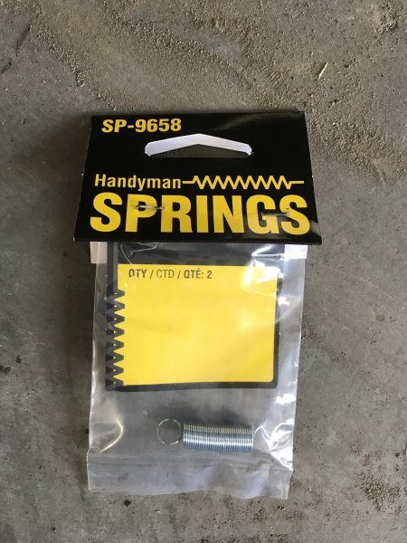
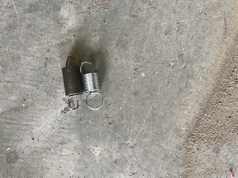
Before I tore the interior apart to repair the floors, I noticed that the parking brake lever would not stay engaged. Every time I depressed the pedal it would spring back up instantly. After searching through the forum I found an amazing write-up by A-man930: http://comancheclub.com/topic/48483-parking-brake-pedal-refurb/ However, I decided to start with the simple as recommended by Cruiser54 on page two. I replaced the stock spring with a new one, as the spring appeared to have lost a lot of its original tension. I made a trip to Ace Hardware and found a spring that sort of matched the stock one. Originally they were to long, I shortened it with same wire cutters. I made it a bit shorter than the stock one to give a bit more tension on the pawl. After the floor has fully cured I'll reinstall the assembly to see if the spring fixed the issue. If not I will remove it again and follow the repair done by A-man930.

-
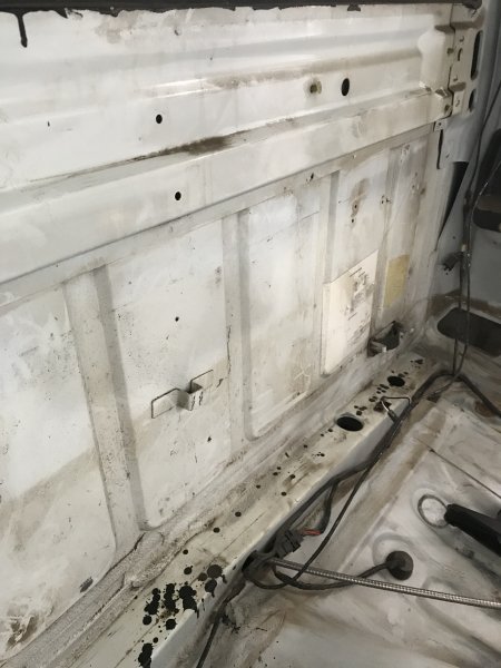
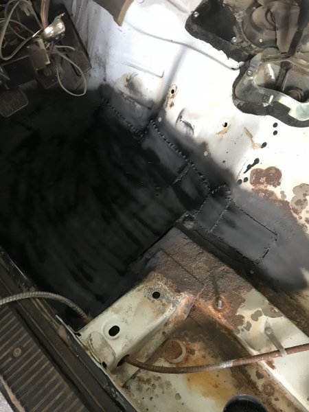
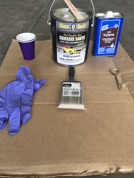
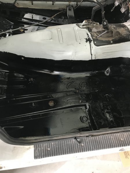
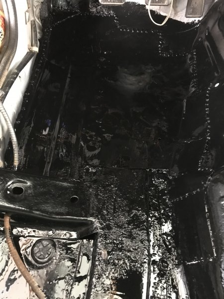
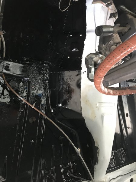
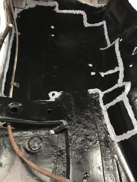
With the floor pans welded into the truck it was time to prevent the remaining rust from spreading, while preventing the new floor pans from succumbing to the same fate as the previous floor pans. I spent more time that I should have reading and debating on which rust inhibitor to go with. I really could not decide whether to go with POR15 or Chassis Saver. Both products have great reviews, so it seemed that I couldn't really go wrong. I finally decided to go with the Chassis Saver as there was less upfront prep work involved. I read through several forums and watched multiple online videos to get any tips for making the process go smoother. The main take aways were remove the loose flaking rust, it does not adhere to bare metal, and don't to let the stuff get on your hands. The directions on the can also recommends scooping only the needed amount into a secondary container and thinning the stuff out with their S8 reducer. A quick check of the SDS sheet shows the S8 is an aromatic hydro carbon, the exact same stuff as xylol. Prep work was straight forward, yet time consuming. As everyone always states, it's all in the prep work. I started with a wire brush to remove any remaining loose/flaky rust. The sections of floor without any rust I scuffed with 60 grit sand paper to remove any sheen on the factory paint for the Chassis Saver to have something to bite onto. Once all the sanding and grinding was completed I vacuumed out all the dust, and wiped everything down with warm soapy water (an idea of how it looked before). After To cover up the bare metal of the recently installed floor pans, they were scuffed with 60 grit sand paper, cleaned with denatured alcohol, and covered in two coats of automotive primer. The automotive primer gives the Chassis Saver something to bond too. Chassis Saver can be applied by spraying or with brush. I went with the brush method. Chassis Saver was applied to the areas where the rust came through as well as areas where there is a potential for water to pool.