


Duncan Moody
-
Posts
23 -
Joined
-
Last visited
Duncan Moody's Achievements
Can Spell Comanche (2/11)
-
I found one through the Facebook group Jeep Renix USA.
-
Looking for a complete wiring harness for 1989 MJ Pioneer long bed, 4.0L, auto trans, A/C. Does anyone have one, or could you please point be to a good source?
-
Dreaded high idle
Duncan Moody replied to Dickinson County Comanche's topic in MJ Tech: Modification and Repairs
Glad it's solved, and appreciate you posting the update. What make CTS did you finally use? -
Ground wire attached to ignition coil
Duncan Moody replied to JefCooks's topic in MJ Tech: Modification and Repairs
Did you figure this out? -
OHM: I saw on another post that you mentioned that if the CPS is too close to the flexplate it confuses it. I have been trying to get it as close as possible without touching, like .010" to get higher voltage signal. Too close? I assume it's hard to quantify a clearance distance due to the variation between sensors.
-
Custom Gaskets for HVAC
Duncan Moody replied to H3ADBANG4L1F3's topic in MJ Tech: Modification and Repairs
Nice work! I improvised with weather stripping, doublesided tape adhesive, and gardening kneeling pads! Not going to open it up and try again though. Hopefully never have to do that again. -
Ohm: Thanks. Using a voltmeter or 12vdc testlight (preferred) check for Battery_Voltage_(B+) on the following pins (use battery_negative terminal for ground): D1_5: B+ (Hot at all times) Yes, 12.4V (Same as battery) D1_6: At KEY ON only (B+ (Hot for 2-3 seconds)). Yes, 12.4. During CRANK Hot at all times. Yes, 11V during crank D2_4: B+ (Hot during KEY ON and Hot during CRANK). Yes, 12.0V on, and 11V during crank acfortier: Thanks. The 2 connectors on the ICM base are tight, no signs of corrosion. I'll try to test it tomorrow.
-
I am hoping to get guidance on next steps to solve my crank, no start problem. I am still optimistic it's something simple that I have missed, not done, or not done right, but I don't know what that is. With help from this group and Mostly Renix on FB, I have ruled out a lot, especially related to the sensor itself, and the signal it produces. Here's what I have, what I have tried, and some data. Any tips or direction will be greatly appreciated, including if you know of a knowledgeable person or shop in the SF Bay Area who can help directly. Thanks. 1989 Comanche Pioneer, 4L, 4x4, Automatic Transmission. (No C101 connector). REM II says CPS Crank Fault. Since it won't run, I am not sure what other useful data REM II can provide. Finally got a CPS installed and positioned to get .695VAC at the sensor connector, and .678VAC backprobing at the ECU connector. Swapped 89 ECU with 88 ECU. Still no change. Ran homerun from CPS to ECU. Did the applicable Cruiser54 tips; 1, 3, 4, 5, 7, 8, 9, 29. New Starter relay and switch. (That solved a temporary no crank condition. I could jump the starter to start it then). New ICM. Ran smoothly and strong before it quit, and also whenever I could get it to start and run. Went through several CPS's; some worked for a while (days/weeks), others not at all. Battery at 12.6V min. Discharged/cleared electrical between tests. (touched black and red when off battery). Attempted to take oscilloscope readings on CPS signal, but was unable to get good readings. I assume I did not have it set up right. Problems started ~6 months after a rebuilt motor was installed a year ago, but not sure how that would contribute. New CPS and new Flexplate (Pioneer FRA333) then, but it ran fine for months before the CPS issues began. Intermittent at first, and temporarily fixed too.
-
Thank you!
-
CPS to ECU home run
Duncan Moody replied to Duncan Moody's topic in MJ Tech: Modification and Repairs
Thanks!! -
Thanks!
-
Looking for details on how to do a home run from CPS to ECU. 1989 4.0 AT. I have no C101. Is it a matter of tracing the wire colors (or continuity) from CPS back to ECU, run new wires through fire wall, then cut and solder at the ECU connector? I could not find ECU connector diagram identifying the CPS connections.
-
Are 1988 and 1989 ECU's essentially the same? If an '88 ECU is used in an '89 Comanche would there be any issues, if so what?
-
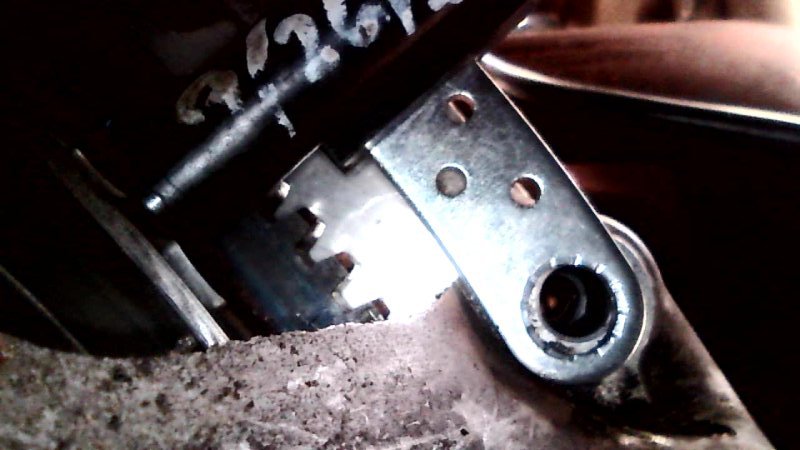
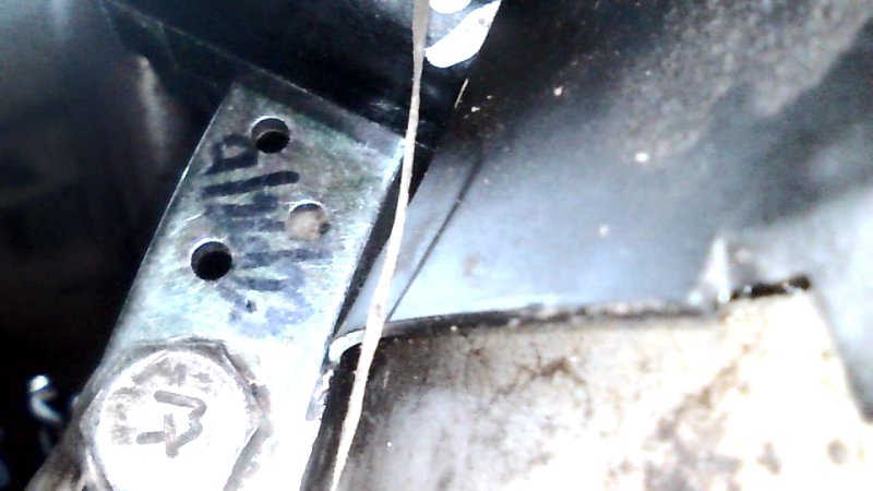
I opened up the upper hole to 3/8" and the output increased slightly - to .26VAC, from .24. Does it make sense to try to get the tip of the sensor closer yet to get to .5? Do you know the optimal clearance? I can't tell if the plastic cover is keeping it from getting closer, but it might be. I could go slightly bigger than 3/8 and/or trim the sensor mounting plate and square boss where it interferes with plastic cover, then stick a paper spacer of the right thickness on the tip to deliver best gap.

-
Thanks for confirming - (and for your valuable contributions to the group). Sorry for missing the info already provided. I have an NTK coming, and I'll see what I get out of it, then if it's still low, make the adjustment. I used the electrician's tape - works good. I also tied a length of dental floss to the bolt when I started the bolt from the top. That doesn't keep you from dropping it, but you can get it if you do.