

tetrad
-
Posts
19 -
Joined
-
Last visited
Content Type
Profiles
Forums
Gallery
Everything posted by tetrad
-
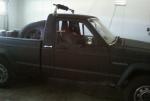
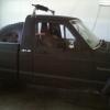
I filled it up with about 2 gallons of gas I had sitting in a tank, and no leaks. Idled it for a few minutes, and no leak. Took it into the smog station and it failed the pressure test and then started leaking again :( I went to a salvage yard where they just got in an 88 MJ, and pulled the sending unit. It looks in much better shape. Not sure which pump I'm going to use. I'll probably be back in the next couple days to pick over it more (it was nearly closing time). It had a 3-piece slider that I'd love to get my hands on :)
-
Well I used JB weld, so here's hoping :) I wasn't able to verify exactly what was leaking, so I did all three fixes (new main o-ring, new wire o-ring and pushnut, slather with JB weld). I got everything put back together and reinstalled. The assembly is missing one of the tangs on the mating surface (rusted off) so it's not sitting entirely straight. I think the lock ring is pressing it into the o-ring tight enough that it won't leak, but it's probably only a matter of time before road vibes wiggle it loose again.
-
I pulled the sender and pump assembly. I'm gonna clean it up and go pick up my new o-rings, lock ring, and push nuts. When I put the new o-rings in, do I lube them up with petroleum jelly or just set them in dry?
-
Awesome, thanks guys. Sounds like a new push-nut + o-ring on the plug and/or epoxy on those hard lines will fix the problem. I now feel confident enough to tear into it and see what the damage is :) 88whitemanche, the link you put at the bottom of the other thread (http://comancheclub.com/topic/38976-gas-tank-leak/?do=findComment&comment=393159) was very helpful as well. I just had CA smog fail due to the gas tank not holding pressure (they pinch the two lines at the charcoal canister and then pressurize it through the filler tube). I think this leak is the source of the problem, but I want to cover my bases to minimize retests. I'm considering also dropping the tank to make sure the ventilation line(s) on top are in good shape, but I'm worried about being able to reuse the straps and nuts.
-
Does that help at all? I initially thought that it was leaking out of the circle about 1.5" out from the center of the pump, but maybe it was just pooling there to drip. Are you suggesting it could be those metal lines coming out of the pump face that are leaking? If so, a new pump and the same tank ought to fix the problem, right?
-
Brake Load Sensing Valve Quick Fix
tetrad replied to 91Pioneer's topic in MJ Tech: Modification and Repairs
I've been wondering what to tie that to. Thank you! :) -
Ah, I got thrown by your username :) Ouch!
-
No I don't have a lot of experience welding aluminum. The tank is the one from mac's radiator that people talk about around here. It's a very nicely made piece even if it's a bit on the expensive side. Cool, thanks! Good luck with the build. What are your plans for the bed?
-
I suggest posting a thread over on the MJ Tech forum for the no-start. Here is a link to Cruiser's Renix tips if you don't have them handy: http://comancheclub.com/topic/36382-cruisers-renix-tips/ It sounds like you've already cleaned up your grounds and coil contacts. If you haven't touched your C101 bulkhead connector, you might want to give Tip #2 a shot. Shouldn't take too long, and a lot of important signals route through it. Did you get a voltage reading with the new CPS?
-
Awesome, thanks for the info and advice :)
-
'88 Eliminator... Feb. 2009 - June 2026
tetrad replied to neohic's topic in Member Projects: Your Comanches
I'm curious what you wired the killswitch up to. I'm guessing as "killswitch" implies, this is an emergency engine shutoff, right? I just read through the entire build thread. This is a great looking truck! :) -
That coolant tank looks slick. Did you fab it yourself?
-
88 4.0L short bed. My gas tank apparently has a decent leak when it's filled over a certain point (had it out on the road for the first time today since I got it, so it's the first fillup). It looks like it's coming out of the pump assembly mating surface, but the pump face and a big swath underneath it are pretty well rusted. I'm guessing it's not something that pulling the pump and throwing in a new gasket would fix. Does anyone have recommendations for a replacement tank (new, salvage, etc)? What else is it a good idea to replace while I'm doing it? Will the tank out of a 2.5L fit and work, or do they have any differences in the pump, sender, etc?
-
SHE LIVES! :thumbsup: I did the C101 delete (and sensor ground fix), still nothing. So I pulled apart the C100 and cleaned it out, still nothing. I pulled my ignition switch off the column and tested it - I was getting +12V at the starter line in start. I pulled off the starter relay coil wires and the terminals were very corroded. Cleaned em up and she started right up :) My dipstick ground is pretty messed up at the moment, which probably took out just enough current to not engage the starter relay with the corrosion. I've got a new full set of cables coming from Jon Kelley (http://www.kelleyswip.com/electric.html), so that shouldn't be an issue for much longer either. Cruiser, thanks to your mantra "RCBRC" I got the jeep running for the cost of some heat-shrink wrap. And I was all excited to go drop a chunk of change on a new ignition switch or starter relay. :yes: I guess I did end up getting an ignition coil and ICM somewhere along the process, but for $20 I'm glad I did it now instead of later.
-
You're supposed to drill the hole on the bracket attached to the CPS, not the hole on the bellhousing, right? I took a file to the bracket hole and expanded it enough to get the CPS closer, and now have 0.5 to 0.7 VAC while cranking -- still no start. [i'm guessing you meant your Tip#7 not Tip#8]. I'm now looking at my ignition coil and module. My coil has a secondary resistance of 2.198 kOhms, and a primary resistance of 0.4 to 0.5 ohms. The secondary seems low. I'm not sure that my ICM is getting a good timing input from the ECU (based on my guess of what a multimeter should show for a square wave). I'll throw an oscilloscope on it within a couple days to verify.
-
I widened the mounting holes on the CPS bracket for the CPS that was originally on the truck. I am now able to adjust it far enough that it scrapes when cranking, then back it off enough to get a cranking CPS voltage of 0.5 to 0.7 VAC. Still no start. CPS is reading 194 ohms at the connector, and 195 ohms at the ECU harness. I tweaked all of the ECU harness female pins to grab better. I verified that I have +12V to the ICM 3-conn "A" pin from the B-latch relay. On the "B" pin, which should be ground, I have 0.3 ohms with the key OFF, and 3.2 ohms with the key ON. Seems a bit odd. I wonder if I might have lost a ground terminal when I refreshed the dipstick ground -- I am supposed to have 1 for the battery negative, and 2 others, right? One of them has 2 wires coming out but they are crimped to the same ring terminal. Also worth noting is that I bled the clutch right before this, and I spilled a decent amount of brake fluid below the master cylinder reservoir. It looks like the wire harness below that goes to the fuse panel. All the fuses checked good, but maybe it shorted something out?
-
I did some work on the Comanche (ground refreshing, full brake job including magic prop valve bleeding, plugs, wires, and distr-cap/rotor) and when I buttoned it all back up I had a no-spark condition. I pulled the ignition coil and shined up the leads. I have 12V to the yellow plug below the ignition coil. I have roughly 36-38 PSI on the fuel rail. While replacing plugs, I did a compression test and have 130+ on all cylinders. I just upgraded to a gauge-cluster (haven't run it since then) and my RPM is nearly pegged to 0 -- it bounces a bit but I think that's just from the Jeep rocking from the starter. Are the RPMs supposed to register during a crank? And if so, it reads that off of the CPS? I have an induction style spark indicator that you just lay on top of the wires. I tested it on the XJ and it definitely lit up. Nothing on the MJ on the IC to distr wire or any distr wire to plug. It sounds like the most likely culprit is the CPS, so I went and got two from the parts store (Carquest, one was a store brand, one was a Wells). They both are testing marginal out of the box (0.2 to 0.3 VAC measured with 1 analog and 2 digital multimeters). The one I pulled off was pretty gunked up, so I cleaned it up and at some point here I'll try throwing it back on. I didn't get a good reading on it before pulling it (somewhere above 0 but below 0.5 VAC). Is it worth trying to slot or expand one of the mounting holes and get it closer to the flexplate? Before I hit the parts store, I called the local Jeep dealer to try to get the CPS straight from them -- they said it's been discontinued, and gave me numbers for a few different Jeep dealers that were showing one in stock so I can try to have them ship it to me. Can anyone else confirm that it's discontinued? I'd like to get a good one in ASAP so I can either go get it smogged or keep troubleshooting the no spark. I've heard that NAPA has good ones, but their online site didn't show a match. -- Cruiser's Tips status: #1 ground refreshing: I pulled the dipstick grounds and shined them up, tightened the stud. My B- to dipstick cable is marginal, but I have a set of new cables from Kelley's WIP coming shortly. When I put that on I will probably chop and re-crimp the sensor ground wires here, but I got a ~0 ohm reading from wires to battery post. I also shined up the braided-cable at the firewall, but didn't pull the side on the head bolt. #2 C101: I pulled it open and it doesn't look terrible. I gave it a quick clean-up pass and threw it back together. At some point I'll eliminate it. #4 Coil/ICM contacts: done.
-
Oh, if you're talking about the wire connectors, they've got a tab on the top and bottom. Mine were pretty stiff so I had to push them in with a screwdriver. The writeup I was using said to note the orientation of those plugs for when you put them back in the new cluster.
-
I just did this earlier today. Do what ParadiseMJ is suggesting. For me, the cable was attached to a bolt on the framerail by one of those little clips, and by taking that off I was able to get about a foot of slack to work with. From the footwell, reach up and thread that cable inside a bit more, then you should be able to see the connector better. Also there is a panel to the right of the cluster that you can take off and maybe see a bit better. There are two little raised bits on either side of the plug, those are what you need to squeeze to pull it off.