Search the Community
Showing results for tags 'how to'.
-
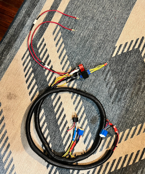
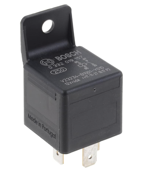
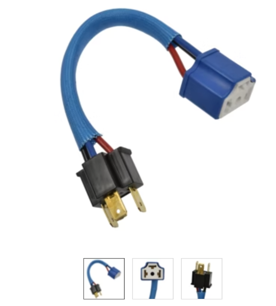
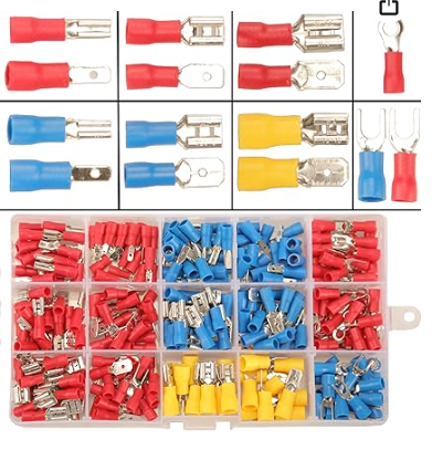
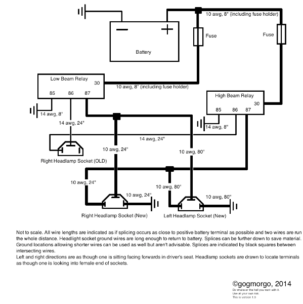
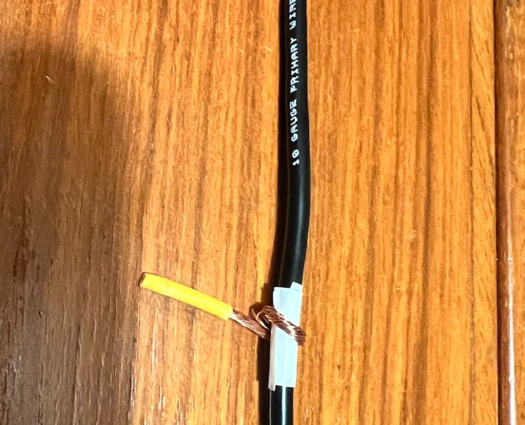
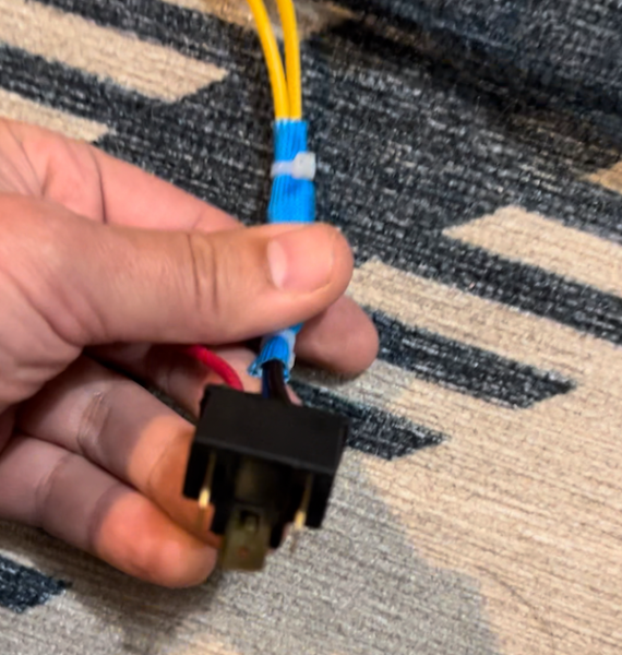
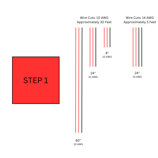
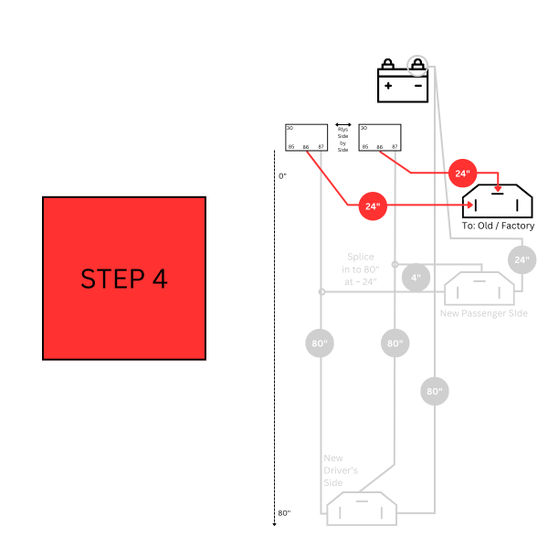
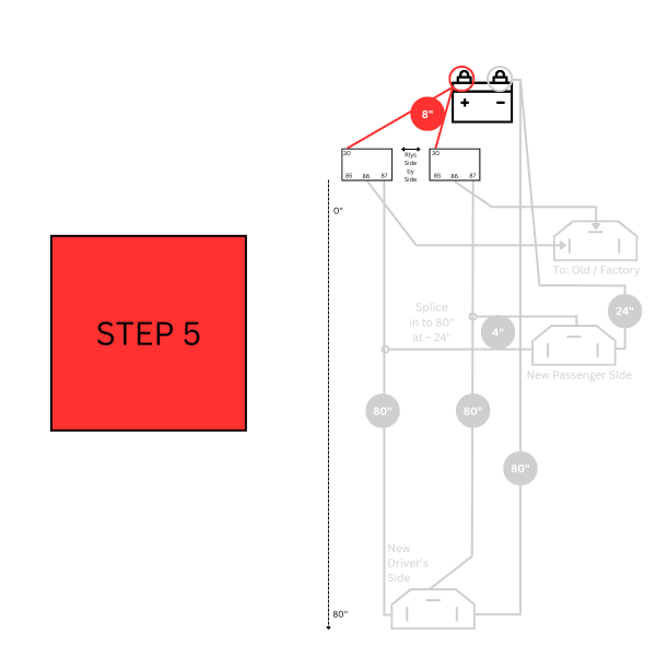
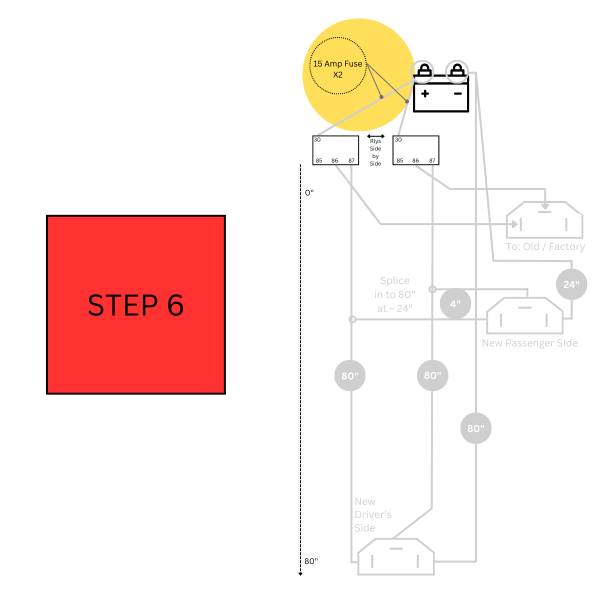
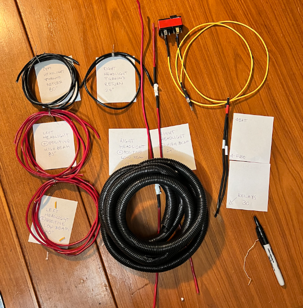
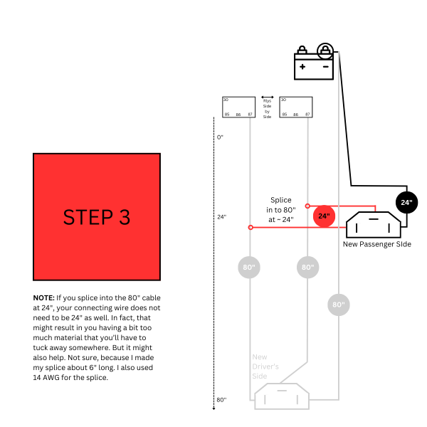
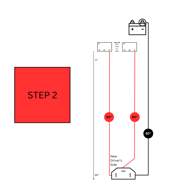
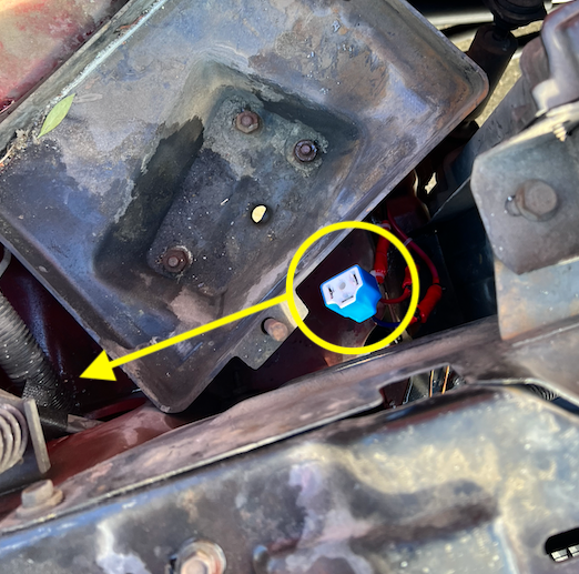
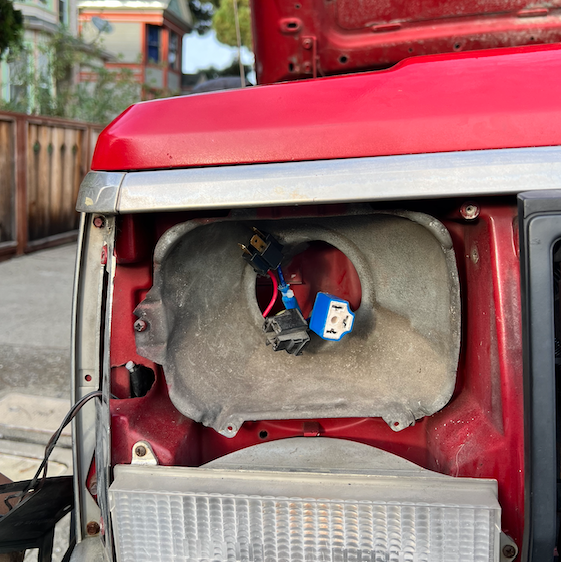
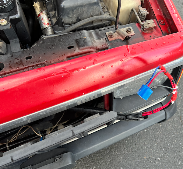
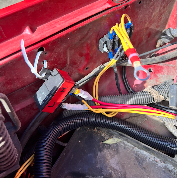
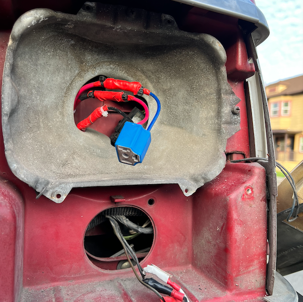
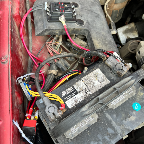
Greetings, Fellow Comanche Enthusiasts! I’ve spent the past few months diving into projects on my 1987 2.5L, 2WD, Short Bed, and this forum has been an invaluable resource. I’ve really enjoyed the time I get to spend just working with my hands and not thinking about emails I have to send. But it occurs to me that I’ve spent a lot of time asking you all questions. I want to give back with a tutorial of my own. I’m much newer to this than many of you, so I welcome any notes on things I could have done better or things I’ve done flat-out wrong. I’m going to write a step-by-step guide on how I built a Headlight Harness Upgrade using @gogmorgo’s diagram. And I’m going to add some diagrams of my own. I hope this ends up helping someone else down the line. NOTE: This is a LONG write up. If you know what you're doing, I suggest taking a look at the diagram below and then the step by step slide show I have at the end. Step 1: Assemble the Materials The first thing I did was add up the total length of 10 AWG and 14 AWG wire that the diagram calls for. The following list turned out to be a little more than I needed, so I think it’s the perfect amount. WIRE: 10 AWG: 30 Feet or 360 Inches 14 AWG: 16 + 48 = 5 Feet or 60 Inches RELAYS: Two 30-amp headlight relays with the following connections: 30, 85, 86, and 87. Here's an example. This one is 40 amps, but you get my drift. H4 HEADLAMP SOCKETS: I scratched my head on this one for a while, because I was unfamiliar with it. Also, all the auto parts websites have my vehicle information by now and they were telling me certain headlights didn’t fit my MJ. I turned off the vehicle-specific search function when I was searching and that helped open up the results. I ultimately went with this one, because it was available locally and the connector was ceramic, which I’ve heard is better than plastic. Makes sense when high temperatures are in play, right? I also wanted to use the male end of one of them to make the connector for the existing OEM harness (see the second picture). OTHER MATERIALS: I had most everything else I needed already, but you’re going to need things like wire strippers/crimpers, big box of wire terminal attachments, a ton of zip ties, and electrical tape. Some other nice-to-haves are a soldering iron, heat shrink wrap, a heat gun, and other electrical components like that. Step 2: Plan Your Build I’ve charged headlong into way too many projects. And honestly, I could have taken more time with this one. But with a project like this, it really helps me to lay everything out in front of me. I looked at @gogmorgo's plans over and over again and cut most of my wire to length before I did anything else. I also labeled my lengths of wire and cross referenced them with the drawings to see if it all made sense. One thing I wish I had done was also plan what kinds of terminal heads I was going to use at each juncture. Doing this would have saved me some time down the line. Step 3: Slow and Steady (Learn From My Mistakes) If you’re brand new, or relatively new (like me), don’t get flustered. Take your time. Like Gogmorgo says, the diagram is not to scale, and it can be hard to visualize at first. Here are some things that took a little while to click for me: Your relays are going to be right next to one another and very close to the battery. Once the new harness is built it will form the shape of a capital “L” — running from the battery on the passenger side of the engine bay, down to the passenger side headlight, then to the driver's side headlight. The short length of the “L” runs from the battery to the passenger side headlight. The long length of the “L” runs from the passenger headlight to the driver’s side headlight. All of the 24-inch lengths of wire correspond to connections at the passenger side headlight. All of the 80-inch lengths of wire correspond to connections as the driver’s side headlight. If you do it like I did, you will have to do at least two splices. These will go on the positive lines. There were two ways I considered doing this. One way would be to connect the positive lines directly to the shovel terminal that attaches to the 87 terminal prongs on each of the two relays (high and low beam). Doing it this way will require the full 24-inches of wire. You may also need to get creative with how you connect the two ends of 10AWG wire to the shovel. Another way is to splice the shorter length of wire roughly at the right angle of the “L” shape that this harness will form when it is installed. Doing it this way will allow you to save a little bit of wire. This second way is the way that I did it. You do not need to splice any of the ground wiring. You do not need to splice the battery-to-relay wiring. Instead, you can just make two 8-inch lengths of wire. On one end attach them to the battery. In the middle, place your in-line fuses. On the other end place a shovel terminal connector to attach to the 30 prong on each relay. If you end up using a left over male H4 connector, remember to connect your wires as a mirror image of the diagram above. I made a mistake here and didn't discover it until the harness was installed. I had to strip wires and make some new connections while crouching at headlight level. Not fun. If you notice, in the picture above, there is a short length of red wire that isn't connected to anything. But that SHOULD have been connected to the high beam relay. Which leads me to No. 7: If you notice in the diagram above, both high beam connections are on the left hand side of the female connector and all the low beam connections are on the top of the female connector. Remember that! Step 4: Splicing & Dicing I was practically brand new to splicing when I started this project. I am also very bad at soldering, and I don’t have a great soldering iron. Here’s how I ultimately spliced the positive cables together: Cut out a very small segment of the 80-inch positive wire. You can use the wire cutters to make the first two cuts around the outer edge of the wire. Then you’ll need a razor blade to cut from one of those cuts to the other cut. Then you’ll peel the slim piece of wire covering off, as if it were a bandage wrapped around your finger. The location of this splice is very close to the connection point for the passenger side headlight connection. The connectors I used came with 14 AWG wires attached to them. I thought about devising a way to maintain 10 AWG all the way to the headlight connection, but I abandoned that idea, and it was helpful to do so. That’s because it was way easier to wrap 14AWG around the exposed splice point of the 10 AWG wire than it would be to wrap the very thick 10 AWG wire around another 10 AWG wire. I took this picture to help you visualize the process. Picture the white electrical tape as the exposed bit on the 10 AWG wire. The yellow bit is 14 AWG wrapped around the exposed portion. Use a soldering iron or thin strips of electrical tape to help secure it in place. As I said, you’ll need to do this on both lengths of 80-inch wire. Step 5: Making Connections Now it’s time to put it all together. For this bit, I made some diagrams of my own. Red is for positive connections. Black is for negative/ground. Connect all the shovel terminals to the wires going to the relays. Connect the new headlight sockets to the wires. Prepare your connection for the existing OEM plug (female plug on the passenger side). I found it helpful to use zip ties to fasten the longer lengths of cable together as I went along. This helped prevent tangles. When I was done, I covered the whole thing in conduit, which I think was helpful when installing in the MJ. MAKE YOUR CUTS MAKE THE DRIVER'S SIDE CONNECTIONS MAKE THE PASSENGER SIDE CONNECTIONS MAKE THE CONNECTIONS FOR THE FACTORY PLUG MAKE YOUR BATTERY CONNECTIONS MAKE AN INLINE FUSE ON THE BATTERY CONNECTIONS Step 6: Hook it Up! I could probably write a whole tutorial on how to do this as well. It took me a long time and I hit some road blocks along the way. Thankfully there is a detailed installation video from K Suspension that you can watch here. The main difference with the harness in this video is that the grounds do not run all the way back to the battery. I opted to create a harness where the grounds return all the way to the battery, because I hoped that would lead to a healthier circuit. By the way, if you don't want to take the time to build your own, or don't feel comfortable doing it, K Suspension and many other companies make this exact harness. Some of them are even cheaper than what it would cost you in money and your valuable time to do it DIY style. But, at least for me, tinkering is part of the fun! Step 6.1: Hook it Up! (Pt. II) OK... Just thought I'd add a few more pics of the actual install. I didn't document this process perfectly. But here goes: It helps to take the batter out completely. This is also good because you know you won't accidentally create a short while the harness is flopping around. This picture is of when I was thinking I'd snake the harness underneath the driver's side of the battery tray, but you'll actually want to snake it under the passenger/fender side. It's a tighter squeeze, but a more optimal flow. Bring the passenger side connections into the passenger headlight bucket. In this image you see the new male connector, the new female connector, and the old factory female connector (clockwise from top). Bring the driver's side connection over to the driver's side bucket, snaking it along behind the grille. I don't have AC (yet). There was a lot of space back there for me. Bring the new driver's side connection into the driver's side headlight bucket. FYI, getting these connections into the buckets was one of the hardest parts of this — at least physically. It's a real contortion act. Be patient. Wear gloves or be prepared to slice up your hands. I also ended up taking out the turn signal on this side. Not sure I needed to, but I got stuck for a while on this step and I wanted a better view. Figure out where you will place your relays. In this picture, you can see where I chose to put my relay and where I decided to put my negative/ground terminal connection. You can use sheet metal screws, but I used zip ties. I might change that in the future. There were many holes already drilled on the interior side of the passenger fender on my '87, which made this pretty easy. Put it all back together. Don't judge me! I need to clean up my battery and replace cables and all that. It's on my list. Anyway, here is the only picture I have in this entire thread of my inline fuses. The fuse block at the top of the pic has a transparent plastic cover, which is good. I will eventually find a better, cleaner way to mount all this stuff, but this is working for now. All right! I think that is it on this now. Se you all in the comments!
-
There are several items for sale in the for sale section that I'm very interested in, but I can't find a reply button. Am I the only 1 or just illiterate?
-
Forgive me if this is a stupid question, but how do you make a submission towards MJOTM? I've been on this forum since January and have seen a lot of awesome, deserving MJ's and their respective owners. I'd like to a take a stab at it as I feel like I may have a chance given then transformation my MJ has had in the past 11 months.
