
SoCalManche
-
Posts
481 -
Joined
-
Last visited
-
Days Won
1
Content Type
Profiles
Forums
Gallery
Everything posted by SoCalManche
-
'86 MJ 2.5L ECM....good?
SoCalManche replied to SoCalManche's topic in MJ Tech: Modification and Repairs
In the past, when I tried to start her up with jumper wire in place of relay, it did not work. I will go try right now. -
'86 MJ 2.5L ECM....good?
SoCalManche replied to SoCalManche's topic in MJ Tech: Modification and Repairs
Not that I'm aware of. I'll give you the big picture on how this issue happened. I was driving to the machine shop to drop off the block of my TJ and I was racing against the clock to get to a gas station to fill up. Well, the truck died about a block away from the gas station, figured from running out of fuel. I found a gas can, threw 5 gal in the tank, and it hasn't fired since (minus throwing a bit of fuel down the TBI). That's where I am today. Grounds have been refreshed since then, and the baseline is still that she will only fire with a bit a fuel thrown down the TBI, with additional grounds added where Cruiser has recommended. -
'86 MJ 2.5L ECM....good?
SoCalManche replied to SoCalManche's topic in MJ Tech: Modification and Repairs
Welp, looks like I'm back to square one when I first attempted to figure out this issue a year ago. -
'86 MJ 2.5L ECM....good?
SoCalManche replied to SoCalManche's topic in MJ Tech: Modification and Repairs
It's the same for my TJ too. Was torx incorrect to say? Star-headed bolt that typically fits a 7/32" ratchet/wrench size. Has a nut on it to torque down the eyelets. -
'86 MJ 2.5L ECM....good?
SoCalManche replied to SoCalManche's topic in MJ Tech: Modification and Repairs
Well the torx bolt is already too stripped to pull out of the block. I had to cut the wires once and re-crimp them with new eyelets after refreshening the ground. I'm contemplating re-cutting and re-crimping the wires again, and the thought of soldering entered my mind. Do you any better ideas than re-crimping? -
'86 MJ 2.5L ECM....good?
SoCalManche replied to SoCalManche's topic in MJ Tech: Modification and Repairs
Ah, okay. I'll have to get a test lamp then. Would it be dumb to solder the wires together that end up at the dipstick tube? -
'86 MJ 2.5L ECM....good?
SoCalManche replied to SoCalManche's topic in MJ Tech: Modification and Repairs
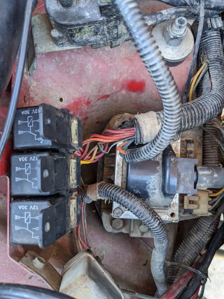
Yes, I can throw a fused jumper wire in pins 87 and 30 and it will immediately start pumping. I did notice after doing my tests a while ago that the relay was cycling quite a bit while key was ON. Is there a way to test for voltage to the injector? I honestly don't think it is getting a proper power supply either. -
'86 MJ 2.5L ECM....good?
SoCalManche replied to SoCalManche's topic in MJ Tech: Modification and Repairs
Maybe the wiring at the dipstick stud is toast? -
'86 MJ 2.5L ECM....good?
SoCalManche replied to SoCalManche's topic in MJ Tech: Modification and Repairs
I also soldered an addition ground to the fuel pump harness and chassis, per Cruiser tip 20-something, and added an addition ground to the driver's side rear taillight grounding point. -
'86 MJ 2.5L ECM....good?
SoCalManche replied to SoCalManche's topic in MJ Tech: Modification and Repairs
I don't have a ground going to alt bracket, but rather from neg post to radiator bracket. Yes confirmed spark. I can dump some fuel into throttle body and it will fire until all fuel added was burned off. -
'86 MJ 2.5L ECM....good?
SoCalManche replied to SoCalManche's topic in MJ Tech: Modification and Repairs
-
'86 MJ 2.5L ECM....good?
SoCalManche replied to SoCalManche's topic in MJ Tech: Modification and Repairs
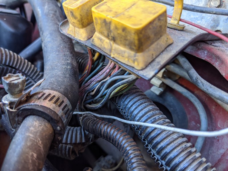
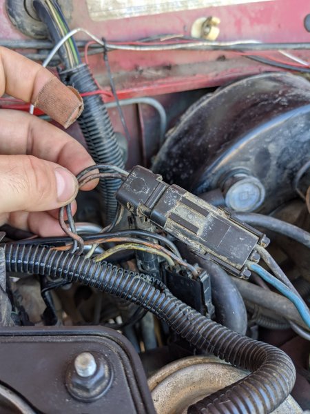
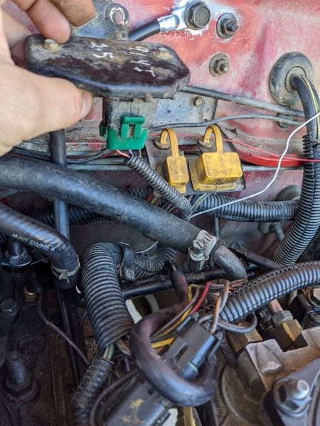
Can you specific how I am supposed to probe? Am I probing between the two at the same time? If so, it reads O.L. I'll send pictures of how the harness looks. In my opinion, it seems in pretty good shape for being 33 years old. -
'86 MJ 2.5L ECM....good?
SoCalManche replied to SoCalManche's topic in MJ Tech: Modification and Repairs
Ha, yeah. Can't be back-probed.
-
'86 MJ 2.5L ECM....good?
SoCalManche replied to SoCalManche's topic in MJ Tech: Modification and Repairs
So right out the gate, the first test is failing. Ground probe at Neg Batt Post, power probe at Terminal B = 10V. Then, in order to probe E33, I took ground probe to E33 while leaving power probe at Terminal B. This gave me 0V. -
'86 MJ 2.5L ECM....good?
SoCalManche replied to SoCalManche's topic in MJ Tech: Modification and Repairs
Welp, looks like we're getting somewhere. Ohms readout: - Firewall: ~12 -Rear engine block: ~10.5 -Dipstick stud: ~10.3 -
'86 MJ 2.5L ECM....good?
SoCalManche replied to SoCalManche's topic in MJ Tech: Modification and Repairs
Yes, the dipstick tube stud is clean. I refreshed it last year while I was initially trying to trace down this problem. I will go check the firewall-block ground, but I want to be transparent and mention I did replace the strap with a 4AWG wire (per Cruiser's tips) after refreshing the contact points. -
'86 MJ 2.5L ECM....good?
SoCalManche replied to SoCalManche's topic in MJ Tech: Modification and Repairs
Let me clarify so that if I'm testing wrong, you can point it out. All testing has been done with key ON, engine OFF, ECU unplugged (since we've been doing ECU terminal testing too). I tried testing ohms from Batt Neg to Terminal A, and got "0.L" again. This was key ON, engine OFF, ECU plugged in. I don't know if ECU plugged/unplugged makes a difference. -
'86 MJ 2.5L ECM....good?
SoCalManche replied to SoCalManche's topic in MJ Tech: Modification and Repairs
I used DCV for the readings. If that is wrong, I apologize. If I switch to ohms, the readings for either remains at "0.L" -
'86 MJ 2.5L ECM....good?
SoCalManche replied to SoCalManche's topic in MJ Tech: Modification and Repairs
A + T17 = ~63mV reading. C + T16 = 0mV reading (Auto'd out to mV). -
'86 MJ 2.5L ECM....good?
SoCalManche replied to SoCalManche's topic in MJ Tech: Modification and Repairs
Okay, so I got a different multimeter (needed a more legit one anyways as I'm slowly learning the ways of the 2.5L electrical gremlins), and wanted to get a baseline check with everything we did two days ago just to make sure we were good to go. Well even though I wasn't worried about the MAP sensor, now I am confused. If I test for voltage for MAP at Terminal C, with ground probe at battery post, I get 10V. If I throw the ground probe in Terminal A and retain the power prove in Terminal C, I get 155mV. If I disconnect ECU and retain ground prove in Terminal A, and put power probe in Terminal 16, I get a baseline reading of 83mV with a slow, but steady increase; I'm sure if I continued to hold it there, it would continue to rise. I also tried both multimeters to verify it wasn't a bad multimeter. -
'86 MJ 2.5L ECM....good?
SoCalManche replied to SoCalManche's topic in MJ Tech: Modification and Repairs
No worries! I'll go buy some tomorrow and then do some tests and get back with the info. -
'86 MJ 2.5L ECM....good?
SoCalManche replied to SoCalManche's topic in MJ Tech: Modification and Repairs
Well this is definitely a piece of information that I've needed! Haha Do you have super long leads bought separately from the multimeter? My leads definitely won't reach... -
'86 MJ 2.5L ECM....good?
SoCalManche replied to SoCalManche's topic in MJ Tech: Modification and Repairs
How do I know which terminals are which? Like I said, kind of a diagnostic novice. If this info is online to reference, I can do that instead of wasting your time, lol. Per this response, my TPS is reading 3.65V at Terminal A. -
'86 MJ 2.5L ECM....good?
SoCalManche replied to SoCalManche's topic in MJ Tech: Modification and Repairs
So then MAP, I would ground probe (A) and power probe (B), yes? As for TPS, my voltage is 1V lower than it should be, yes? How would one remedy that? -
'86 MJ 2.5L ECM....good?
SoCalManche replied to SoCalManche's topic in MJ Tech: Modification and Repairs
Let me ask a question that just popped into my brain. How should I be testing the voltage? I was testing the same way I tested for ohms. Negative lead to negative battery post, and positive lead to respective connector. Also, MAP (B) is reading 3.9 - 4.1V.