Korsch_RS Posted December 1, 2016 Author Share Posted December 1, 2016 Drivetrain: NP 242 T-case is mounted to the 4L70 with Novak parts. I’m using the output shaft speed sensor integrated into the adapter for the ECM speed signal, and the stock Jeep electric sender I nabbed from the junkyard to drive my new electric speedometer. I had the output shaft and new tailhousing professionally installed, and the trans rebuilt with some better internals too at the same time. I had to modify my trans crossmember quite a bit to work with the new trans mounting location, including cutting a big notch out of it for the t-case, and making some room to route 2 exhaust pipes over it. If I was doing it again, I would just build one from scratch using some 1x6 or 2x6 steel box tubing. The transfer case sits 2” farther forward than stock. I didn’t have any problems with clearance to the floor with my NP242. For driveshafts, I just brought them to a local place and had the front shortened by 2”, the rear lengthened by 2”, and both rebalanced for about $300. I already had a Novak cable shifter on my AX-15, and according to their website this shifter will work with the 4L60 and NP 242, so I thought this would be an easy thing. Unfortunately, I was wrong. The t-case bracket tries to put the cable linkage inside the body of the transmission. I ended up modifying the stock transmission shift bracket to fit the t-case shifter. It’s a very tight fit trying to fit the cable between the larger transmission body and the driveshaft yoke. The size of the transmission pushes the cable outboard a little bit, so you can’t get a straight shot at the shift lever on the t-case. For shifting the transmission, I used a B&M pro stick that I modified following Billavista’s “ultimate offroad shifter” thread on pirate4x4 (http://www.pirate4x4.com/tech/billavista/shifter/). I had to modify the B&M bracket to shift the cable to the otherside of the lever in order to make room for the t-case shifter cable. Link to comment Share on other sites More sharing options...
reson46 Posted December 1, 2016 Share Posted December 1, 2016 Is this the tail housing you used? https://www.novak-adapt.com/catalog/adapters/transmission-to-transfer-case/4l60e-to/kit-4l61/ I was wondering if it came with a mounting location for the VSS? It isn't clear on the Novak site. Thanks, Willy Link to comment Share on other sites More sharing options...
Korsch_RS Posted December 2, 2016 Author Share Posted December 2, 2016 Yup it is, and yes it does. The kit includes the sensor that the factory GM harness plugs into. The sensor sits very close to the transmission side flange, it's actually frenched into the flange a little bit. You can just barely see it in the first picture above. Link to comment Share on other sites More sharing options...
reson46 Posted December 2, 2016 Share Posted December 2, 2016 Yup it is, and yes it does. The kit includes the sensor that the factory GM harness plugs into. The sensor sits very close to the transmission side flange, it's actually frenched into the flange a little bit. You can just barely see it in the first picture above. Great! I noticed the hole in your pic and I was hoping it was for the VSS. The pic on the Novak site appears to show a VSS in the collection of parts, but it isn't listed in the contents. Thanks, Willy Link to comment Share on other sites More sharing options...
ggcnash Posted December 6, 2016 Share Posted December 6, 2016 Link to comment Share on other sites More sharing options...
Comanche SS Posted December 9, 2016 Share Posted December 9, 2016 Just for your reference of the ls1 style setup does fit under the hood, with Novak engine mounts. Also, how do you like the 242? I just swapped my 231 for the 241 and I am liking it so far! Also, are you keeping the 8.8 and d30 with the power upgrades? I have a d44, built d30 setup and I am conflicted as to go d44 front and rear, just want another LS comanche owners .02. Sent from my XT1585 using Tapatalk Link to comment Share on other sites More sharing options...
Korsch_RS Posted December 14, 2016 Author Share Posted December 14, 2016 Your engine bay looks really nice and tidy! Did you mount the ECM in the cab? 242 is ok, I liked it better with the 4.0L. I haven't driven full-time 4wd mode in the snow yet, but in the rain if I get on the gas around corners, the rear end slides almost like it was in 2wd, not grip and go like the AWD in my WRX. I think it's a combination of the low weight/traction in the back, and also because the 242 doesn't have a LSD in the center, so if the rear starts spinning it just send all the power back there like an open diff in an axle. The 4.0L didn't really have the torque to break the rear loose in AWD mode. We'll have to see in the snow though, I think it will still be better than just 2wd, but I'll just have to be mindful of 400hp under my right foot instead of 180. Yup keeping the d30 for now, it has stock big joint shafts and a truetrac. A coworker of mine has a nicely built TJ with an LS6 and an 8.8/d30 that he takes to the sand dunes every weekend. I think he's only gone through 2 ring and pinions in the 10 years he's had that thing, and it gets beat on every weekend. Eventually I'd like the Dynatrac Pro-Rock 44 that I can bolt my current knuckles onto to keep the steering and brakes the same, just get the upgraded R&P. Side note, I've updated the first few swap posts with some added pictures Link to comment Share on other sites More sharing options...
Comanche SS Posted December 15, 2016 Share Posted December 15, 2016 Your engine bay looks really nice and tidy! Did you mount the ECM in the cab? 242 is ok, I liked it better with the 4.0L. I haven't driven full-time 4wd mode in the snow yet, but in the rain if I get on the gas around corners, the rear end slides almost like it was in 2wd, not grip and go like the AWD in my WRX. I think it's a combination of the low weight/traction in the back, and also because the 242 doesn't have a LSD in the center, so if the rear starts spinning it just send all the power back there like an open diff in an axle. The 4.0L didn't really have the torque to break the rear loose in AWD mode. We'll have to see in the snow though, I think it will still be better than just 2wd, but I'll just have to be mindful of 400hp under my right foot instead of 180. Yup keeping the d30 for now, it has stock big joint shafts and a truetrac. A coworker of mine has a nicely built TJ with an LS6 and an 8.8/d30 that he takes to the sand dunes every weekend. I think he's only gone through 2 ring and pinions in the 10 years he's had that thing, and it gets beat on every weekend. Eventually I'd like the Dynatrac Pro-Rock 44 that I can bolt my current knuckles onto to keep the steering and brakes the same, just get the upgraded R&P. Side note, I've updated the first few swap posts with some added pictures Thank you, and good to know. My D30 has chromolys with the bigger joints as well. Stock knuckles though. I am planning on linking the rear end after new years, I don't know if you know, youll need metric ton springs to prevent axle wrap, but it rides rough, so links are the best option. My MJ has the 23.5 gallon tank, so I am going 3 link and panhard to maintain the fuel delivery system I have. My ECM is mounted on custom brackets behind the passenger seat, it is raised off of the floor and I have a custom Painless wiring harness throughout the entire jeep with two main fuse boxes. I am waiting on my front driveshaft to be made, (converted to 1350 and 1410 joints). Locked 4wd and lockers will be insane on these little trucks. Link to comment Share on other sites More sharing options...
Korsch_RS Posted February 1, 2017 Author Share Posted February 1, 2017 Exhaust: I’m using ceramic coated Novak swap headers for my truck. I went with ceramic coating because I was worried about cooling the engine, so I wanted to keep engine bay temps as low as possible. The exhaust starts as 2x 2.5” pipes, merges to a single 3.5” behind the trans crossmember, then goes down to 3” just before the rear axle before going through a high flow cat and muffler. I went down to 3” so I could use a cat and muffler I already had from a previous project, if I was buying new I would do 3.5” or 4”. I’ve actually been really happy with the way the truck sounds. It’s a little rowdy when you’re on the gas, but cruising down the freeway you really can’t hear the exhaust over the tire noise. If I was runnnig All-terrains you could probably hear it. I think the catalytic converter actually helps keep the volume down a lot, as the Magnaflow muffler is just a straight through design. The biggest problem I’ve had is clearance between the drivers side pipe and the driveshaft. With the high pinion dana 30 the driveshaft get very close to the bellhousing. I’ve ovaled the pipe with a hammer a lot, but it still hits a bit, so I think I’m going to have to do something a bit more drastic. I don’t want to just bumpstop it more as my uptravel is already compromised by trying to keep the truck low. If you’re running 6”+ of lift or a low pinion front axle this probably wouldn’t be a problem at all. Link to comment Share on other sites More sharing options...
Quarterpastgone Posted February 1, 2017 Share Posted February 1, 2017 I read you used painless wiring harness for your truck, do you have part numbers for it. I am about to have to rewrite my whole truck while doing 5.3 swap. Link to comment Share on other sites More sharing options...
Korsch_RS Posted February 1, 2017 Author Share Posted February 1, 2017 I actually made my own harness for everything. I'll have a post up all about the electrical side of things soon. I think Comanche SS used a painless harness, his build thread is here: http://comancheclub.com/topic/50978-comanche-ss-ls-swapped-la-locked-and-soon-to-be-linked/?do=findComment&comment=519297 Good luck! LS V8's are a lot of fun in these trucks :) Link to comment Share on other sites More sharing options...
Comanche SS Posted February 2, 2017 Share Posted February 2, 2017 I read you used painless wiring harness for your truck, do you have part numbers for it. I am about to have to rewrite my whole truck while doing 5.3 swap. I actually made my own harness for everything. I'll have a post up all about the electrical side of things soon. I think Comanche SS used a painless harness, his build thread is here: http://comancheclub.com/topic/50978-comanche-ss-ls-swapped-la-locked-and-soon-to-be-linked/?do=findComment&comment=519297 Good luck! LS V8's are a lot of fun in these trucks :) Mine does have the painless harness... Also, liking the headers/exhaust...just an FYI the ridgid headers to collector is what I have running on mine right now, and its not good, once it heats up and warps a bit it leaks, you (and me for that matter) need a flex/banjo pipe on one of the down pipes so they both seal against the headers. pics attatched...my exhaust is currently being worked on as well. I have the same headers, but v bands instead of normal flanges. I talked to another one of my LS-MJ buddies, and he actually used a LP D30 to drop the pinion a bit. not a half bad idea as long as you arent going crazy big power or tires. I May do that to mine and swap my 6" metalcloak coils to the 4.5s... Link to comment Share on other sites More sharing options...
Korsch_RS Posted February 9, 2017 Author Share Posted February 9, 2017 Alright, now we’re getting into the harder parts of this swap, plumbing and electrical Plumbing: Fuel Walbro 255lph fuel pump installed in the tank. These are available almost anywhere, I got mine from Summitracing Then I used this kit which has the filter/regulator and AN fittings and hose http://www.tanksinc.com/index.cfm/page/ptype=product/product_id=453/category_id=61/mode=prod/prd453.htm These hoses just go straight onto the stock fuel tank barbs with a couple hose clamps. The return nipple was technically a little too small for the hose, but it’s low pressure and I put 2 hose clamps on it, and it’s hasn't leaked yet. I ran rubber fuel hose all the way up to the fuel rail, with a short section of heat shielding where it gets within a few inches of the exhaust. Power Steering Lots of people use the stock hard lines from the steering box and LS power steering pump, and crimp a new soft line in between them, but I didn’t have the PS pump side hardline so I made my own stainless braided flex line with -6 AN fittings. The PS system runs at a pretty high pressure so you need hose that’s capable of holding it. For the return side I just used a leftover -6 AN fitting and hose from the fuel system. You’ll also need adapters to connect AN fittings to the metric o-ring ports on the steering box and pump. The pump uses a M16 o-ring to -6 AN fitting, and the box uses 1x M16 and 1x M18 o-ring to -6AN fittings. Here’s what I used: This didn’t turn out to be a very clean installation, I’m not a huge fan of how the line has to loop, and the pump fittings get extremely close to the pulley. I will probably re-do this in the future if I can find a better way to connect the hose to the pump and clear the pulley. I did find this fitting later, I may try it out at some point to see if it cleans up these lines and improves clearance to the pulley (https://www.summitracing.com/parts/FLA-FR1634). Coolant I’m using a heavy duty CSM 3-row brass/copper stock replacement radiator. I already had this radiator from before, so I figured since it was already much bigger than stock I would try it with the LS. So far it’s actually been pretty good. Most driving around the engine sits between 195 and 210. I haven’t had it offroad much yet to really test it though, so if it give me any problems I’m just going to go straight for the gigantic Novak aluminum unit. Connecting the LS coolant ports to the stock radiator was a little difficult as the LS ports are both on the passenger side. For the lower hose I used a straight thermostat housing (ebay), 2 90deg hoses, some straight aluminum pipe, and some clamps. I had to oval one section of the aluminum pipe to clear the stock electric fan motor, but if you use a slimmer fan you probably won’t have to do this. On the upper hose, I used 2 90deg bends again, this time with a 90deg bent aluminum pipe (I got mine from Woolf aircraft products, a local place) to clear the intake tube. In the second picture you can see where I drilled and tapped the straight thermostat housing for the steam port. This isn't technically the right way to do it, the best way is to run this steam tube into the top of the radiator, however because I'm using a stock style radiator right now, it doesn't have a port for the steam tube. I saw some people on LS1tech doing it this way and it was working for them. For now, I don't think there are any issues, the truck runs well and hasn't overheated, so I think it's ok for now. For the heater hoses, I just used some 5/8" and 3/4" heater hose from the local auto parts store. I used a new heater valve with better port orientation to replace the stock one (Murray P/N 74781, I think it’s from an Astrovan?). The LS relies on the heater circuit flow for the thermostat to work correctly, so you need to run these hoses, or at least a loop hose across the ports on the water pump. This side of the engine bay has a lot of hoses going everywhere and needs some more cleaning up. I used Roadkill zip-tie wire/hose keepers to try and keep everything a bit more organized. The heater hoses, transmission cooler hoses, transmission vent hose, and vacuum ball hose are all running on this side of the engine bay, along with both the engine and transmission dipsticks, so it's a little crowded. https://www.youtube.com/watch?v=Fll_OPtYsJE Coolant overflow is handled by a bottle I picked up on amazon which I think was originally for a toyota truck. It’s mounted to the passenger side fender well, with a hole in the side of the truck for the vent to exit the engine bay. Transmission Cooler I used a B&M Transmission cooler and some -8 AN Fittings and hose from Summitracing. I originally made a bracket and mounted my cooler in front of the drivers side rear tire, but that didn’t work very well so I moved it in front of the radiator like normal. You will need NPSM (National Pipe Straight Male) adapters to connect the AN fittings to the transmission ports, and I needed NPT (National Pipe Tapered) adapters to connect the AN hose to the cooler. I used 2x 90deg AN hose ends on the transmission side, and 1x 90deg and 1x straight hose end on the cooler side. I like to use field serviceable hose end fittings instead of crimp on because then I can assemble hoses in the garage, and make changes later if needed. Here’s some more info from the LS forums about running -8 AN trans cooler line: http://ls1tech.com/forums/automatic-transmission/1397578-wanna-run-8-trans-cooler-line.html Link to comment Share on other sites More sharing options...
Comanche SS Posted February 19, 2017 Share Posted February 19, 2017 Everything is looking great! Glad to see you doing every thing pretty correctly and not cutting a to of corners! Keep updates rolling Sent from my XT1585 using Tapatalk Link to comment Share on other sites More sharing options...
500 MJ Posted February 19, 2017 Share Posted February 19, 2017 Good seeing you this weekend at our friend's wedding. Just read the whole build thread and I'm super jealous, you've done some work to this truck! Watching the build from here and looking forward to what's to come! Link to comment Share on other sites More sharing options...
Korsch_RS Posted February 21, 2017 Author Share Posted February 21, 2017 Thanks Brent! It was fun to catch up and talk Comanches with you over the weekend Electrical: I decided to use the stock v8 engine harness as a base, but make my own complete new truck harness for everything forward of the seats. The only stock MJ wiring I’m using are the two connectors by the drivers foot that go through that power the b-pillar lights, fuel pump, and taililghts. This was actually way easier than I thought it would be. The key was to take things one circuit at a time. My basic process was this: Remove the stock harness from the engine/trans, label every connector as I take it off with masking tape and a sharpie Take all the loom and electrical tape off everything De-pin any connector from the LS harness that I wasn’t going to use on my truck (mainly the fuse box connectors) Go through the ECM/TCM connectors and remove pins for the emissions systems I was removing. Mount all the major components where I wanted them (ECM, TCM, Fuse boxes, etc…) Plug the harness into the mounted ECM Going one circuit at a time, lay out all the sensor, injector, and other engine wires across the engine bay how I want them to run, and loosely place the wires into those spots. Shorten or lengthen the wires as required (Only do one wire at a time!). Use zipties to loosely hold things in place, loose enough so I can put additional wires through those locations. This is just the things that are already done on the stock harness (injectors, MAF/MAP, coils, crank position sensor, etc…) and just need to be shortened/lengthened. After the engine circuits are finished, start laying out the circuits that need to interface with the truck itself As each circuit gets placed, write down the wire color and pin number of each connector as you go. I made a big spreadsheet with all my connectors and pinouts on it, and started with almost all of it blank. As I completed each circtuit, I filled in the pinouts for each connector that that circuit connected to. There are some pictures of all my wiring documentation below. Some pictures of the process. With the wires going everywhere, I think it looks a lot worse than it really was. The most important thing is just to be methodical; take it one wire at a time, label everything, and then double check your labels. Here’s some of the resources I used Alldatadiy.com great resource for just about every electrical component pinout and wiring diagram on the vehicle. Requires paid subscription, but it’s paid for itself too many times to count. I would not attempt an engine swap using the stock harness ever again without buying the diagrams here. Used this thread as a rough guide to how I modified my harness http://www.pirate4x4.com/forum/general-4x4-discussion/881167-my-ls2-harness-diy-chop.html Waytekwire.com My source for most of my electrical parts, including fuseboxes and power relays (except Deutsch connectors/pins, most of those I got directly from LADD Industries). Interior Fuse Box https://www.waytekwire.com/item/45990/Littelfuse-868-163-HWB60-Base/ Engine Bay fuse box - one bus bar carries full time +12V, the other carries ignition switched 12V https://www.waytekwire.com/item/46354/Bussmann-15401-2-0-1-0A-RFRM-Panel-/ The extra relays on the right side are for the fans. When we’ve used these micro relays for some constant high load (20-30A) applications before at work, we’ve occasionally overheated them, so for the fans I picked up a Hella four-relay block and attached it to the fuse box bracket. It hold full-size relays for the fans. Both the fuseboxes use Metri-pack 280 terminals (WITH Tangs! Delphi 12077411) and seals/plugs (Delphi 15324983, 15324982, 15324980, and 12010300), and fit mini-ATM fuses and micro relays. The 280 stands for 2.8mm, which is the width of the pins on the fuses and relays that slide into the terminals in the fuse boxes. These also require a special crimper which I borrowed from my work, but you can find cheaper ones on amazon. I eventually bought one of the cheaper ones and it does the job, just not as well as the expensive real-deal one. Power Relay Modules - 2 of these are used to fuse and supply both constant 12V and ign switched 12V to the fuse boxes https://www.waytekwire.com/item/46095/Bussmann-37702-1AN0022-Power-Relay-Module-/ Anywhere I needed a connector but I wasn’t using a stock GM or Jeep one, I used weatherproof Deutsch connectors. Best place to get the real thing is direct from LADD Industries. McMaster also sells some Deutsch style connectors that are weatherproof, and will connect to the real deal (https://www.mcmaster.com/#deutsch-compatible-connectors/=154y9o6). These connectors do require a special crimping tool. I got lucky and borrowed one from my work. The biggest connector was the firewall pass through. I used a Deutsch DRB series connector with 48 pins. This connector required a new steel plate that I just epoxied to the bulkhead. You could easily skip this and use the stock pass through connector to avoid this hassle and expense, but mine wasn’t in very good condition, and I wanted something that would seal better. Parts List for the DRB connector and pins: 1x of DRB12-48PAE-L018 1x of WB-48PA 1x of DRBF-2A 1x of DRB16-48SAE-L018 1x of WB-48SA 30x of 0460-202-20141 15x of 0460-202-16141 15x of 0460-204-12141 30x of 0462-201-20141 15x of 0462-201-16141 15x of 0462-203-12141 This connector is slightly smaller than the stock unit. I made a plate out of ⅛ steel that had the correct hole cut out in it the for DRB connector, and used one of the DRB bolts through one of the stock bolt holes, and a separate screw through the other stock bolt hole. Because this wasn’t structural, I decided to try glueing it on, so I got some metal-to-metal epoxy and glued it on. Unfortunately I didn’t take any photos of the process, but here’s the finished product I made some spreadsheets for each connector, and as I went I filled all the wiring information in for each pin. I ended with a big stack of wiring diagrams specific to my truck. The stack in the top left is the print-out of all the ECM connectors and and pins, and their functions. The top right is the pinout of the DRB bulkhead connector (I still need to add a picture of the connector to that one). The bottom left is the packet for the interior fuse box and all the connectors, and the bottom right is the packet for the engine bay fuse box and all the connectors. Here’s a closer look at one of the pages in the interior packet. I just took a picture of each connector and labeled the pins using powerpoint, and then just put the pictures into excel with some tables for pin number, wire color, and description. I tried to write notes about where wires go-to or come-from, and maybe a basic description of function. Before I started the actual I tried to fill in as many boxes as I could, and then as I built the wiring harness I wrote down the pins, colors, and wires as I added them, or I jotted down notes if I wanted to add some detail to what I had already entered before. The next step after the wiring harness is all made it to go back and update the electronic versions of all these documents with whats in the truck and re-print them out and keep them in the truck. That way if I run into any electrical gremlins down the road I have all the documentation available to help diagnose. Link to comment Share on other sites More sharing options...
Comanche SS Posted February 21, 2017 Share Posted February 21, 2017 You used all the same fuse boxes, relays, and connectors I did, except the twist connect engine and trans harnesses. You'll love it. I have my Main fuse box where the stock intake goes on these jeeps, the interior and lights fuse box under the dash, and the ecu is behind the seats. Sent from my XT1585 using Tapatalk Link to comment Share on other sites More sharing options...
Korsch_RS Posted February 22, 2017 Author Share Posted February 22, 2017 You used all the same fuse boxes, relays, and connectors I did, except the twist connect engine and trans harnesses. You'll love it. I have my Main fuse box where the stock intake goes on these jeeps, the interior and lights fuse box under the dash, and the ecu is behind the seats. Sent from my XT1585 using Tapatalk Yeah Cooper Bussman and Littlefuse make some nice products. I really like how much cleaner your installation looks with the ECM hidden away, but I didn't want to pass so many wires through my firewall, and I was already filling up the 48 pins on my pass through. I like how your fusebox is farther forward then mine, I'm thinking about moving mine forward a bit more this summer, and try to free up some room to make a cold air box for the intake in the back corner. Link to comment Share on other sites More sharing options...
Comanche SS Posted February 22, 2017 Share Posted February 22, 2017 You used all the same fuse boxes, relays, and connectors I did, except the twist connect engine and trans harnesses. You'll love it. I have my Main fuse box where the stock intake goes on these jeeps, the interior and lights fuse box under the dash, and the ecu is behind the seats. Sent from my XT1585 using Tapatalk Yeah Cooper Bussman and Littlefuse make some nice products. I really like how much cleaner your installation looks with the ECM hidden away, but I didn't want to pass so many wires through my firewall, and I was already filling up the 48 pins on my pass through. I like how your fusebox is farther forward then mine, I'm thinking about moving mine forward a bit more this summer, and try to free up some room to make a cold air box for the intake in the back corner. Yeah I gotcha, yours is looking great. Sent from my XT1585 using Tapatalk Link to comment Share on other sites More sharing options...
Korsch_RS Posted March 2, 2017 Author Share Posted March 2, 2017 Post-LS Swap Once I got the engine in and running, I drove it around for a little while still on the old suspension (Rough country 3” XJ lift front, AAL and extended shackles back) and went to some local car meets, most people really likes seeing an LS in an old Jeep :) Unfortunately I was getting pretty tired of how rough the short arms and AAL lift was, it was pretty harsh going over any bump in the road. Unfortunately I started throwing a P0894 code “Transmission Slip Detected”. This was causing the transmission to go into a limp-home mode and max line pressure for all shifts. It would chirp the tires going into third gear at low throttle openings, and beyond being uncomfortable, this would sometimes make the truck slide rather alarmingly if there was any moisture on the ground. I ended up pulling the transmission back out to go back to the Trans guy to get torn apart again and the problem investigated. Link to comment Share on other sites More sharing options...
Korsch_RS Posted March 2, 2017 Author Share Posted March 2, 2017 While the truck was down with the trans out, I decided to redo the suspension with some DIY Long arms. I originally wanted to do a 3-link, but there just wasn’t enough space to fit the upper link under the truck with the bigger engine, transmission, and exhaust pipes getting in the way, so I ended up settling on a single-Y radius arm setup. I swapped the UCA joint on the diff with a Currie Johnny Joint so I could get a larger ½” bolt now that I only had one UCA. I also plated the front half of the frame (rear will be done this summer) and added some air-bumps to smooth out the ride with my limited ride height and up-travel, and upped the lift a little bit with some MetalCloak Dual-Rate lift springs. I put some cheap white-body 12” travel shocks on it for now just to get it on the road, it will be getting something nicer later (Fox/Kings). No going back now! Beefy 1.25” Heims LCA’s mounts tacked on and LCA’s mocked up I went with SPC Performance 1.5” travel JounceShock air-bumps because they had some nice parts available to make the mounting and installation a lot easier. The steel cups shown here are threaded to accept the bump, so you just weld that on wherever you want it and thread the bump into it. I found a nice place to mount the bumpstops underneath the frame rail and they contact the axle on the flat part of the truss between the coil pad and the differential. I had to trim one little stiffening rib of the diff to make the whole pad flat. Passenger side was hitting the sloped part of the truss, so I ended up cutting that out and welding in a flat part for the bumpstop. All put together I also siped my BfGoodrich KM2 tires while the truck was apart to try and improve the wet weather/snow traction. This is just the pattern I came up with. Link to comment Share on other sites More sharing options...
Comanche SS Posted March 2, 2017 Share Posted March 2, 2017 How is your anti dive? What length is the lower arm? Sent from my XT1585 using Tapatalk Link to comment Share on other sites More sharing options...
Korsch_RS Posted March 15, 2017 Author Share Posted March 15, 2017 Front LCA's are about 31" long and sit almost perfectly flat. I can feel the anti-dive pretty significantly, the front stays higher under brakeing than it did before. I can also feel the passenger side (where it's just a LCA and not a y-link) want to dive more than the drivers side under hard braking, but it's not enough to feel unstable, just a little weird. I'm working on a front sway bar now that should help reduce that. The transmission guy tore my trans all apart and found the 3-4 clutches were burned up, and a groove in one of the bands, but couldn’t find anything that would have caused those problems unfortunately. He also sent my Torque Converter back to the shop that built it and hooked me up with a new one in case the problem was in there somewhere. I took some datalogs with a Tech2 I borrowed from work and it was showing a couple hundred rpm slip across the TC when it was supposed to be locked up, so there may have been an issue inside there somewhere. Once I got it back I put the truck back together with the new front suspension. I picked up HPTuners to better datalog the rebuilt trans, and do some tuning. I’ve never been a fan of the way most automatics shift, so I wanted to dial this one in the way I wanted. First drive with the transmission in and front Long Arms! And then I ripped a brake line off, luckily it was as I was backing into my driveway. It looks like the long brakelines rested against the LCA right about where the tire would get close when turning, so it looks like a tire lug snagged the line and ripped it right off the caliper end when I turned the wheels hard to back in. I ordered some new lines and whipped up a spring to hold them out of the way of the tire, but allow them to stretch out when the suspension articulates. It’s hard to see but one end of the spring is under the coil retention bracket bolt, and the other end is ziptied to the middle of the brake line. They’re pretty soft springs, about 3-4” long normally and I can stretch them out to 8-10” by hand. Link to comment Share on other sites More sharing options...
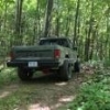
Korsch_RS Posted March 15, 2017 Author Share Posted March 15, 2017 After improving the front suspension so much, I had to do something about the stock leaves with AAL in the back. I ordered some Rusty’s Offroad 4.5” lift springs. Added some 3/4” spacers to the front to level it out a bit These new leaves flex and ride way better than the old ones. I went up to the middle of Michigan’s Lower Peninsula for some snow wheeling to test out all the changes :) Once aired down the KM2’s did well in the deep snow. At around 10psi they would ride up on the snow with gentle throttle, but if you got in the power they would just dig down really fast. I was playing around with some friends of mine, and they took some burst shots of me fooling around and I turned them into gifs. When I was looking at these, I confirmed something I had been suspecting with the V8 torque and flexy springs. My rear axle is wrapping pretty bad. Which means it’s time to install the RuffStuff Traction Bar kit I’ve had lying around for a while! Link to comment Share on other sites More sharing options...
Korsch_RS Posted March 15, 2017 Author Share Posted March 15, 2017 I welded the C’s to the axle as close to the pumpkin as I could. One is directly welded to the tube, about an inch from where the tube goes into the pumpkin. The other I actually trimmed down and welded it direct to the pumpkin. I preheated the cast steel until I couldn’t touch it at all, and then double passed all my welds with the welder cranked to the max. I only have a 110v :( Because the MJ doesn’t have a tradition frame with cross members, I tied the chassis shackle mount into the back of the cab. I plated the back corner with 1/8” steel, and welded a bit of 2”x2”x0.188” square tube to lower the upper mount, which is welded to the bushing sleeve part. I used some of the leftover parts from my long arm kit to make the bar adjustable. Here’s the lower bar, 2” OD 0.25” wall steel with the bracket for the upper bar heim. And here’s the assembled traction bar. The upper is 1.5” OD 0.25” wall And looking back you can see the relatively central location of the bar on the axle, and how I welded one of the C’s to the differential casting I had to rejig the exhaust a bit to snake around the traction bar. I also added some v-band flanges to the cat because I’ve been having problems with those connections coming loose and the truck suddenly getting incredibly loud. The traction bar made a huge difference to the way the truck handles. I couldn’t ever floor it before because the rear would squat really badly, and you could feel it squirming all over the place. With the traction bar is squats a little, but not much, and just hooks up and goes. Going over bumps or cracks in the road on the power the truck is much more stable and composed too. I’m super happy with how it’s performing overall now. Link to comment Share on other sites More sharing options...

Recommended Posts
Create an account or sign in to comment
You need to be a member in order to leave a comment
Create an account
Sign up for a new account in our community. It's easy!
Register a new accountSign in
Already have an account? Sign in here.
Sign In Now